Table of Contents
Advertisement
Quick Links
Advertisement
Table of Contents

Related Manuals for ASROCK C621A WS


Summary of Contents for ASROCK C621A WS
- Page 2 (including damages for loss of profits, loss of business, loss of data, interruption of business and the like), even if ASRock has been advised of the possibility of such damages arising from any defect or error in the documentation or product.
- Page 3 If you require assistance please call ASRock Tel : +886-2-28965588 ext.123 (Standard International call charges apply)
-
Page 4: Table Of Contents
Contents Chapter 1 Introduction Package Contents Specifications Motherboard Layout Onboard LED Indicators I/O Panel Chapter 2 Installation Screw Holes Pre-installation Precautions Installing the CPU and Heatsink Installation of Memory Modules (DIMM) Expansion Slots (PCIe Slots) Jumper Setup Onboard Headers and Connectors Unit Identification purpose LED/Switch Driver Installation Guide 2.10... - Page 5 Advanced Screen 3.3.1 CPU Configuration 3.3.2 Chipset Configuration 3.3.3 Storage Configuration 3.3.4 ACPI Configuration 3.3.5 USB Configuration 3.3.6 Super IO Configuration 3.3.7 Serial Port Console Redirection 3.3.8 H/W Monitor 3.3.9 AMD CBS 3.3.10 AMD PBS 3.3.11 PSP Firmware Versions 3.3.12 Instant Flash Server Mgmt 3.4.1 System Event Log 3.4.2 BMC Network Configuration...
- Page 6 Chapter 4 Software Support Install Operating System Support CD Information 4.2.1 Running The Support CD 4.2.2 Drivers Menu 4.2.3 Utilities Menu Chapter 5 Troubleshooting Troubleshooting Procedures...
-
Page 7: Chapter 1 Introduction
ASRock’s website without further notice. If you require technical support related to this motherboard, please visit our website for specific information about the model you are using. You may find the latest VGA cards and CPU support list on ASRock’s website as well. ASRock website http://www.asrock.com. -
Page 8: Specifications
1.2 Specifications Platform • ATX Form Factor • 12 Layer PCB • 2oz Copper PCB • Supports 3rd Generation Intel® Xeon® Scalable Processors • Intel® Socket 4189 (Socket P+) • Digi Power Design • 7 Power Phase Design Chipset • Intel® C621A Memory • Eight Channel Memory Technology (1DPC) • 8 x DDR4 DIMM Slots... - Page 9 * Supports Intel® Optane Technology * Supports NVMe SSD as boot disks * Supports ASRock U.2 Ki RAID • Supports RAID 0, RAID 1, RAID 5 and RAID 10 for SATA storage devices • Supports RAID 0, RAID 1, RAID 5 for M.2 NVMe storage...
- Page 10 • 1 x 8 pin 12V Power Connector (Hi-Density Power Connector) • 1 x 4 pin 12V Power Connector (Hi-Density Power Connector) • 1 x Vertical Type A USB 2.0 • 1 x USB 2.0 Header (Supports 2 USB 2.0 ports) (Supports ESD Protection) • 1 x USB 3.2 Gen1 Headers (Support 2 USB 3.2 Gen1 ports) (Supports ESD Protection)
- Page 11 • ErP/EuP ready (ErP/EuP ready power supply is required) * For detailed product information, please visit our website: http://www.asrock.com Please realize that there is a certain risk involved with overclocking, including adjusting the setting in the BIOS, applying Untied Overclocking Technology, or using third-party overclocking tools.
-
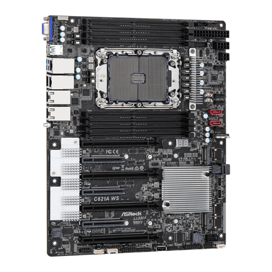
Page 12: Motherboard Layout
LAN1 FAN4 SATAPWR1 SATA_5 LAN2 DDR4_G1 SATA_4 DDR4_H1 UID1 DDR4_E1 FAN5 DDR4_F1 BAT1 PCIE7 CLRMOS1 PCIE6 SATA_0_3 PCIE5 PCIE4 C621A WS PCIE3 PCIE2 ROM1 PCIE1 SPEAKER1 USB_2_3 BIOS ROM1 ME_RECOVERY1 PASSWORD_CLEAR NMI_BTN2 ESPI_LPC_SEL1 SEC_OR1 PECI1 USB_1 BIOS_RECOVERY ESPI_SHARE ESPI_MODE1 MINISAS_1... - Page 13 C621A WS Description Backplane PCI Express Hot-Plug Connector (CPU1_HSBP1) PSU SMBus Header (PSU_SMB1) System Fan Connector (FAN1) ATX Power Connector (ATXPWR1) ATX 12V Power Connector (ATX12V1) USB 3.2 Gen1 Header (USB3_5_6) ATX 12V Power Connector (ATX12V2) System Fan Connector (FAN2)
- Page 14 Description Vertical USB 2.0 Port (USB_1) Front LAN LED Header (FRONT_LED_LAN34) TPM Header (TPM1) SATA SGPIO Connector (SATA_SGPIO1) SATA SGPIO Connector (SSATA_SGPIO1) Thermal Sensor Header (TR1) MiniSAS HD SATA/PCIE Slection Jumper (MINISAS_1) BMC SMBus Header (BMC_SMB_1) ESPI Flash Sharing Jumper (ESPI_SHARE) Intelligent Platform Management Bus Header (IPMB1) COM Header (COM1) BIOS Recovery Jumper (BIOS_RECOVERY1)
-
Page 15: Onboard Led Indicators
C621A WS 1.4 Onboard LED Indicators... - Page 16 Item Status Description SB_PWR1 Green STB PWR ready FAN_LED1 Amber FAN1 failed FAN_LED2 Amber FAN2 failed FAN_LED3 Amber FAN3 failed FAN_LED4 Amber FAN4 failed FAN_LED5 Amber FAN5 failed BLED1 Green BMC heartbeat LED...
-
Page 17: I/O Panel
C621A WS 1.5 I/O Panel No. Description No. Description VGA Port (VGA1) 1G LAN RJ-45 Port (LAN4)** USB 3.2 Gen1 Ports (USB3_3_4) 10G LAN RJ-45 Port (LAN1)*** LAN RJ-45 Port (IPMI_LAN)* 10G LAN RJ-45 Port (LAN2)*** USB 3.2 Gen1 Ports (USB3_1_2) - Page 18 *There are two LED next to the LAN port. Please refer to the table below for the LAN port LED indications. ACT/LINK LED SPEED LED LAN Port Dedicated IPMI LAN Port LED Indications Activity / Link LED Speed LED Status Description Status Description...
- Page 19 C621A WS ***There are two LEDs on each LAN port. Please refer to the table below for the LAN port LED indications. ACT/LINK LED SPEED LED LAN Port LAN Port (LAN1, LAN2) LED Indications Activity / Link LED Speed LED...
-
Page 20: Chapter 2 Installation
Chapter 2 Installation This is an ATX form factor (12” x 9.6”, 30.5 cm x 24.4 cm) motherboard. Before you install the motherboard, study the configuration of your chassis to ensure that the motherboard fits into it. Make sure to unplug the power cord before installing or removing the motherboard. Failure to do so may cause physical injuries to you and damages to motherboard components. -
Page 21: Installing The Cpu And Heatsink
C621A WS 2.3 Installing the CPU and Heatsink 1. Before you insert the CPU into the socket, please check if the PnP cap is on the socket, if the CPU surface is unclean, or if there are any bent pins in the socket. Do not force to insert the CPU into the socket if above situation is found. - Page 22 1. Before you installed the heatsink, you need to spray thermal interface material between the CPU and the heatsink to improve heat dissipation. 2. Illustration in this documentation are examples only. Heatsink or fan cooler type may differ. CPU Carrier...
- Page 23 C621A WS...
- Page 24 CPU Carrier...
- Page 25 C621A WS Heatsink CPU Carrier Socket...
-
Page 27: Installation Of Memory Modules (Dimm)
C621A WS 2.4 Installation of Memory Modules (DIMM) This motherboard provides eight 288-pin DDR4 (Double Data Rate 4) DIMM slots in two groups, and supports Eight Channel Memory Technology. CPU1 1 DIMM 2 DIMMS 4 DIMMS 8 DIMMS 1. It is not allowed to install a DDR, DDR2 or DDR3 memory module into a DDR4 slot;... -
Page 29: Expansion Slots (Pcie Slots)
C621A WS 2.5 Expansion Slots (PCIe Slots) There are 7 PCIe slots on this motherboard. PCIE slot: PCIE1, PCIE3, PCIE5 and PCIE7 (PCIE 4.0 x16 slot, from CPU1) are used for PCIe x16 lane width cards. PCIE2, PCIE4 and PCIE6 (PCIE 4.0 x8 slot, from CPU1) are used for PCIe x8 lane width cards. - Page 30 Installing an expansion card Step 1. Before installing an expansion card, please make sure that the power supply is switched off or the power cord is unplugged. Please read the documentation of the expansion card and make necessary hardware settings for the card before you start the installation. Step 2.
-
Page 31: Jumper Setup
C621A WS 2.6 Jumper Setup The illustration shows how jumpers are setup. When the jumper cap is placed on the pins, the jumper is “Short”. If no jumper cap is placed on the pins, the jumper is “Open”. The illustration shows a 3-pin jumper whose pin1 and pin2 are “Short”... - Page 32 BIOS Recovery Jumper (3-pin BIOS_RECOVERY1) (see p.6, No. 45) Normal Mode (Default) Recover BIOS ESPI/LPC Selection Jumper (3-pin ESPI_LPC_SEL1) (see p.6, No. 54) ESPI (Default) ESPI Flash Sharing Jumper (3-pin ESPI_SHARE) (see p.6, No. 42) Master ESPI Flash Sharing Slave ESPI Flash Sharing (Default) The illustration shows how jumpers are setup.
-
Page 33: Onboard Headers And Connectors
C621A WS 2.7 Onboard Headers and Connectors Onboard headers and connectors are NOT jumpers. Do NOT place jumper caps over these headers and connectors. Placing jumper caps over the headers and connectors will cause permanent damage to the motherboard. System Panel Header... - Page 34 Auxiliary Panel Header This header supports multiple (18-pin AUX_PANEL1) functions on the front panel, (see p.6, No. 30) including the front panel SMB, internet status indicator and chassis intrusion pin. A. Front panel SMBus connecting pin (6-1 pin FPSMB) This header allows you to connect SMBus (System Management Bus) equipment. It can be used for communication between peripheral equipment in the system, which has slower transmission rates, and power management equipment.
- Page 35 C621A WS IntA_PA_D+ USB 3.2 Gen1 Header Besides four default USB 3.2 IntA_PA_D- IntA_PA_SSTX+ (19-pin USB3_5_6) Gen1 ports on the I/O panel, IntA_PA_SSTX- (see p.6, No. 6) there is one USB 3.2 Gen1 IntA_PA_SSRX+ IntA_PA_SSRX- header on this motherboard. Vbus This USB 3.2 Gen1 header can...
- Page 36 USB_PWR USB 2.0 Header This is one header on (9-pin USB_2_3) this motherboard. This DUMMY (see p.6, No. 27) USB 2.0 header can support two ports. USB_PWR ATX Power Connector This motherboard provides a (24-pin ATXPWR1) 24-pin ATX power connector. (see p.6, No.
- Page 37 C621A WS TPM-SPI Header This connector supports (13-pin TPM_BIOS_PH1) Trusted Platform Module (see p.6, No. 32) (TPM) system for SPI interface, which can securely store keys, digital certificates, passwords, and data. A TPM system also helps enhance network security, protects digital identities, and ensures platform integrity.
- Page 38 Serial ATA3 DOM The SATA3 DOM connectors SATA_5 Connectors support both SATA DOMs (SATA_4) (Disk-On-Module) and SATA (see p.6, No. 18) data cables for internal storage SATA_4 (SATA_5) devices. (see p.6, No. 16) SATA_5 Serial ATA3 Connectors These two SATA3 connectors Vertical: support SATA data cables for (SATA_4)
- Page 39 C621A WS Thermal Sensor Header Please connect the thermal (2-pin TR1) sensor cable to either pin 1-2 (see p.6, No. 39) or pin 2-3 and the other end to the device which you wish to monitor its temperature. Front LAN LED Header...
- Page 40 Virtual RAID On CPU This connector supports Intel® Header Virtual RAID on CPU and VROC RAID KEY (4-pin RAID_1) NVME/AHCI RAID on CPU +3VSB (see p.6, No. 28) PCIE. With the introduction of the Intel VROC product, there are three modes of operation: HW key required Key features • Pass-thru only (no RAID)
-
Page 41: Unit Identification Purpose Led/Switch
C621A WS 2.8 Unit Identification purpose LED/Switch With the UID button, You are able to locate the server you’re working on from behind a rack of servers. Unit Identification When the UID button on the purpose LED/Switch front or rear panel is pressed,... -
Page 42: M.2_Ssd (Ngff) Module Installation Guide
2.10 M.2_SSD (NGFF) Module Installation Guide The M.2, also known as the Next Generation Form Factor (NGFF), is a small size and versatile card edge connector that aims to replace mPCIe and mSATA. The Ultra M.2 Socket (M2_1) supports a M.2 SATA3 6.0 Gb/s module or a M.2 PCI Express module up to Gen3 x4 (32Gb/s) The M.2 Socket (M2_2) supports a M.2 SATA3 6.0 Gb/s module or a M.2 PCI Express module up to Gen3 x1 (8 Gb/s). - Page 43 C621A WS Step 3 Move the standoff based on the module type and length. Skip Step 3 and 4 and go straight to Step 5 if you are going to use the default nut. Otherwise, release the standoff by hand.
-
Page 44: Chapter 3 Uefi Setup Utility
Chapter 3 UEFI Setup Utility 3.1 Introduction This section explains how to use the UEFI SETUP UTILITY to configure your system. The UEFI chip on the motherboard stores the UEFI SETUP UTILITY. You may run the UEFI SETUP UTILITY when you start up the computer. Please press <F2> or <Del> during the Power-On-Self-Test (POST) to enter the UEFI SETUP UTILITY;... -
Page 45: Navigation Keys
C621A WS 3.1.2 Navigation Keys Please check the following table for the function description of each navigation key. Navigation Key(s) Function Description Moves cursor left or right to select Screens Moves cursor up or down to select items + / - To change option for the selected items <Tab>... -
Page 46: Main Screen
3.2 Main Screen Once you enter the UEFI SETUP UTILITY, the Main screen will appear and display the system overview. The Main screen provides system overview information and allows you to set the system time and date. -
Page 47: Advanced Screen
C621A WS 3.3 Advanced Screen In this section, you may set the configurations for the following items: CPU Configuration, Chipset Configuration, Storage Configuration, ACPI Configuration, USB Configuration, Super IO Configuration, Serial Port Console Redirection, H/W Monitor, AMD CBS, AMD PBS, PSP Firmware Versions and Instant Flash. -
Page 48: Cpu Configuration
3.3.1 CPU Configuration SVM Mode Enable or disable CPU Virtualization. Node 0 Information View Memory Information related to Node 0. -
Page 49: Chipset Configuration
C621A WS 3.3.2 Chipset Configuration SPI/LPC TPM Switch Use this item to switch SPI/LPC TPM. OnBrd/Ext VGA Select Select between onboard or external VGA support. Onboard LAN1 This allows you to enable or disable the Onboard LAN1 feature. Onboard LAN2 This allows you to enable or disable the Onboard LAN2 feature. - Page 50 PCIE Slot 4 Link Width This allows you to select PCIE4 Link Width. The default value is [x16]. PCIE Slot 5 Link Width This allows you to select PCIE5 Link Width. The default value is [x16]. PCIE Slot 6 Link Width This allows you to select PCIE6 Link Width.
- Page 51 C621A WS SR-IOV Support If system has SR-IOV capable PCIe Devices, this option Enables or Disables Single Root IO Virtualization Support. Restore AC Power Loss This allows you to set the power state after a power failure. If [Power Off] is selected, the power will remain off when the power recovers.
-
Page 52: Storage Configuration
3.3.3 Storage Configuration SATA Hot Plug Enable/disable the SATA Hot Plug Function. -
Page 53: Acpi Configuration
C621A WS 3.3.4 ACPI Configuration PCIE Devices Power On Allow the system to be waked up by a PCIE device and enable wake on LAN. RTC Alarm Power On Use this item to enable or disable RTC (Real Time Clock) to power on the system. -
Page 54: Usb Configuration
3.3.5 USB Configuration Legacy USB Support Use this option to enable or disable legacy support for USB devices. The default value is [Enabled]. -
Page 55: Super Io Configuration
C621A WS 3.3.6 Super IO Configuration Serial Port 1 Configuration Use this item to set parameters of Serial Port 1 (COM1). Serial Port Use this item to enable or disable the serial port. Change Settings Use this item to select an optimal setting for Super IO device. -
Page 56: Serial Port Console Redirection
3.3.7 Serial Port Console Redirection COM1 / SOL Console Redirection Use this option to enable or disable Console Redirection. If this item is set to Enabled, you can select a COM Port to be used for Console Redirection. Console Redirection Settings Use this option to configure Console Redirection Settings, and specify how your computer and the host computer to which you are connected exchange information. - Page 57 C621A WS Bits Per Second Use this item to select the serial port transmission speed. The speed used in the host computer and the client computer must be the same. Long or noisy lines may require lower transmission speed. The options include [9600], [19200], [38400], [57600] and [115200].
- Page 58 Redirect After POST When Bootloader is selected, then Legacy Console Redirection is disabled before booting to legacy OS. When Always Enable is selected, then Legacy Console Redirection is enabled for legacy OS. Default setting for this option is set to Always Enable. Serial Port for Out-of-Band Management/Windows Emergency Management Services (EMS) Console Redirection...
-
Page 59: H/W Monitor
C621A WS 3.3.8 H/W Monitor In this section, it allows you to monitor the status of the hardware on your system, includ- ing the parameters of the CPU temperature, motherboard temperature, CPU fan speed, chassis fan speed, and the critical voltage. - Page 60 FAN 5 This allows you to set the fan 5’s speed. The default value is [Smart Fan]. FAN 6 This allows you to set the fan 6’s speed. The default value is [Smart Fan]. FAN 7 This allows you to set the fan 7’s speed. The default value is [Smart Fan]. Smart Fan Control This allows you to set the Smart fan’s level speed.
-
Page 61: Amd Cbs
C621A WS 3.3.9 AMD CBS CPU Common Options Use this item to configure CPU Common options. DF Common Options Use this item to configure DF Common options. UMC Common Options Use this item to configure UMC Common options. NBIO Common Options Use this item to configure NBIO Common options. -
Page 62: Amd Pbs
3.3.10 AMD PBS Use this item to configure AMD CPM RAS related settings. -
Page 63: Psp Firmware Versions
C621A WS 3.3.11 PSP Firmware Versions The PSP Firmware Verions displays the version information of PSP Recovery BL, PSP BootLoader, SMU FW, ABL, APCB, APDB, and APPB. -
Page 64: Instant Flash
3.3.12 Instant Flash Instant Flash is a UEFI flash utility embedded in Flash ROM. This convenient UEFI update tool allows you to update system UEFI without entering operating systems ® first like MS-DOS or Windows . Just save the new UEFI file to your USB flash drive, floppy disk or hard drive and launch this tool, then you can update your UEFI only in a few clicks without preparing an additional floppy diskette or other compli- cated flash utility. -
Page 65: Server Mgmt
C621A WS 3.4 Server Mgmt Wait For BMC Wait For BMC response for specified time out. BMC starts at the same time when BIOS starts during AC power ON. It takes around 90 seconds to initialize Host to BMC interfaces. -
Page 66: System Event Log
3.4.1 System Event Log SEL Components Change this to enable ro disable event logging for error/progress codes during boot. Erase SEL Use this to choose options for earsing SEL. When SEL is Full Use this to choose options for reactions to a full SEL. Log EFI Status Codes Use this item to disable the logging of EFI Status Codes or log only error code or only progress code or both. -
Page 67: Bmc Network Configuration
C621A WS 3.4.2 BMC Network Configuration Lan Channel (Failover) Manual Setting IPMI LAN If [No] is selected, the IP address is assigned by DHCP. If you prefer using a static IP address, toggle to [Yes], and the changes take effect after the system reboots. The default value is [No]. - Page 68 The default login information for the IPMI web interface is: Username: admin Password: admin...
-
Page 69: Bmc Tools
C621A WS 3.4.3 BMC Tools Load BMC Default Settings Use this item to Load BMC Default Settings. -
Page 70: Security
3.5 Security In this section, you may set or change the supervisor/user password for the system. For the user password, you may also clear it. Supervisor Password Set or change the password for the administrator account. Only the administrator has authority to change the settings in the UEFI Setup Utility. Leave it blank and press enter to remove the password. -
Page 71: Key Management
C621A WS 3.5.1 Key Management In this section, expert users can modify Secure Boot Policy variables without full authenti- cation. Factory Key Provision Install factory default Secure Boot keys after the platform reset and while the System is in Setup mode. - Page 72 b) EFI_CERT_X509 (DER encoded) c) EFI_CERT_RSA2048 (bin) d) EFI_CERT_SHA256, 384, 512 2. Authenticated UEFI Variable 3. EFI PE/COFF Image(SHA256) Key Source: Default, External, Mixed, Test Key Exchange Keys Enroll Factory Defaults or load certificates from a file: 1. Public Key Certificate in: a) EFI_SIGNATURE_LIST b) EFI_CERT_X509 (DER encoded) c) EFI_CERT_RSA2048 (bin)
- Page 73 C621A WS 1. Public Key Certificate in: a) EFI_SIGNATURE_LIST b) EFI_CERT_X509 (DER encoded) c) EFI_CERT_RSA2048 (bin) d) EFI_CERT_SHA256, 384, 512 2. Authenticated UEFI Variable 3. EFI PE/COFF Image(SHA256) Key Source: Default, External, Mixed, Test Authorized TimeStamps Enroll Factory Defaults or load certificates from a file: 1.
-
Page 74: Boot Screen
3.6 Boot Screen In this section, it will display the available devices on your system for you to configure the boot settings and the boot priority. Boot Option #1 Use this item to set the system boot order. Boot Option #2 Use this item to set the system boot order. - Page 75 C621A WS Setup Prompt Timeout Configure the number of seconds to wait for the UEFI setup utility. Bootup Num-Lock If this item is set to [On], it will automatically activate the Numeric Lock function after boot-up. Boot Beep Select whether the Boot Beep should be turned on or off when the system boots up. Please note that a buzzer is needed.
-
Page 76: Csm Parameters
3.6.1 CSM Parameters Enable to launch the Compatibility Support Module. Please do not disable unless you’re running a WHCK test. If you are using Windows Server 2012 R2 or later ver- sions 64-bit UEFI and all of your devices support UEFI, you may also disable CSM for faster boot speed. - Page 77 C621A WS PCIE3 Slot OpROM Use this item to select slot storage and Network Option ROM policy. In Auto option, the default is Disabled with NVMe device, but it is Legacy with other devices. (This item can't select Video Option ROM policy.) PCIE4 Slot OpROM Use this item to select slot storage and Network Option ROM policy.
-
Page 78: Event Logs
3.7 Event Logs Change Smbios Event Log Settings This allows you to configure the Smbios Event Log Settings. When entering the item, you will see the followings: Smbios Event Log Use this item to enable or disable all features of the SMBIOS Event Logging during system boot. - Page 79 C621A WS entries which utilize a multiple-event counter. The value ranges from 0 to 99 minutes. Log EFI Status Code Enable or disable the logging of EFI Status Codes as OEM reserved type E0 (if not already converted to legacy).
-
Page 80: Exit Screen
3.8 Exit Screen Save Changes and Exit When you select this option, the following message “Save configuration changes and exit setup?” will pop-out. Press <F10> key or select [Yes] to save the changes and exit the UEFI SETUP UTILITY. Discard Changes and Exit When you select this option, the following message “Discard changes and exit setup?”... - Page 81 C621A WS Chapter 4 Software Support 4.1 Install Operating System This motherboard supports various Microsoft® Windows® Server 2012 R2 / Linux compliant. Because motherboard settings and hardware options vary, use the setup procedures in this chapter for general reference only. Refer to your OS documentation for more information.
- Page 82 Chapter 5 Troubleshooting 5.1 Troubleshooting Procedures Follow the procedures below to troubleshoot your system. Always unplug the power cord before adding, removing or changing any hardware com- ponents. Failure to do so may cause physical injuries to you and damages to motherboard components.
- Page 83 C621A WS Unable to save system setup configurations... 1. Verify if the battery on the motherboard provides ~3VDC. Install a new battery if it does not. 2. Confirm whether your power supply provides adaquate and stable power.
- Page 84 Contact Information If you need to contact ASRock or want to know more about ASRock, you’re welcome to visit ASRock’s website at http://www.asrock.com; or you may contact your dealer for further information. For technical questions, please submit a support request form at https://event.asrock.com/tsd.asp...
- Page 85 Address: Phone/Fax No: +1-909-590-8308/+1-909-590-1026 hereby declares that the product Product Name : Motherboard C621A WS Model Number : Conforms to the following speci cations: FCC Part 15, Subpart B, Unintentional Radiators Supplementary Information: is device complies with part 15 of the FCC Rules. Operation is subject to the...
- Page 86 EU Declaration of Conformity For the following equipment: Motherboard (Product Name) C621A WS / ASRock (Model Designation / Trade Name) ASRock Incorporation (Manufacturer Name) 2F., No.37, Sec. 2, Jhongyang S. Rd., Beitou District, Taipei City 112, Taiwan (R.O.C.) (Manufacturer Address) EMC —Directive 2014/30/EU (from April 20th, 2016)
Need help?
Do you have a question about the C621A WS and is the answer not in the manual?
Questions and answers