
Related Manuals for Middle Atlantic Products RM-KB-LCD17x8KVM


Summary of Contents for Middle Atlantic Products RM-KB-LCD17x8KVM
- Page 1 Dual Rail 8-Port & 16-Port LCD KVM Switch RM-KB-LCD17x8KVM RM-KB-LCD17x16KVM User Manual Phone: 973 839 1011 www.middleatlantic.com I-00386-2 Rev B...
-
Page 2: Fcc Information
RM-KB-LCD17x8/16KVM User Manual FCC Information This is an FCC Class A product. In a domestic environment this product may cause radio interference in which case the user may be required to take adequate measures. This equipment has been tested and found to comply with the limits for a Class A digital device, pursuant to Part 15 of the FCC Rules. -
Page 3: User Notice
RM-KB-LCD17x8/16KVM User Manual User Notice All information, documentation, and specifications contained in this manual are subject to change without prior notification by the manufacturer. The manufacturer makes no representations or warranties, either expressed or implied, with respect to the contents hereof and specifically disclaims any warranties as to merchantability or fitness for any particular purpose. -
Page 4: Package Contents
1 Easy Installation Rack Mount Kit (includes four bracket screws) 8 Rack Mount Screws with Washers 4 10 feet (3 meters) Hybrid KVM Cable (for RM-KB-LCD17x8KVM) 8 10 feet (3 meters) Hybrid KVM Cable (for RM-KB-LCD17x16KVM) 1 Five in One USB/PS2 Console Cable... -
Page 5: Table Of Contents
RM-KB-LCD17x8/16KVM User Manual Contents FCC Information ..........ii RoHS. - Page 6 RM-KB-LCD17x8/16KVM User Manual On Screen Display (OSD) Operation OSD Overview ..........31 OSD Login .
- Page 7 RM-KB-LCD17x8/16KVM User Manual Technical Support ......... . . 61 Specifications .
-
Page 8: About This Manual
RM-KB-LCD17x8/16KVM User Manual About this Manual This user manual is provided to help you get the most from your RM-KB- LCD17x8/16KVM system. It covers all aspects of installation, configuration and operation. An overview of the information found in the manual is provided below. -
Page 9: Conventions
RM-KB-LCD17x8/16KVM User Manual Conventions This manual uses the following conventions: Indicates text that you should key in. Monospaced Indicates keys you should press. For example, [Enter] means to press the Enter key. If keys need to be chorded, they appear together in the same bracket with a plus sign between them: [Ctrl+Alt]. - Page 10 RM-KB-LCD17x8/16KVM User Manual This Page Intentionally Left Blank...
-
Page 11: Introduction
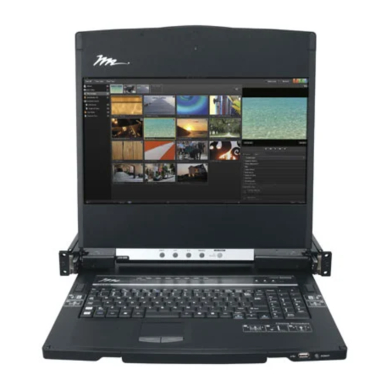
Chapter 1 Introduction Overview The RM-KB-LCD17x8/16KVM switch is an integrated LCD console and keyboard, video, and mouse (KVM) switch that offers secure access to 8 or 16 attached computers and mounts in only 1U of rack space. It features an independently retractable 17”... - Page 12 RM-KB-LCD17x8/16KVM User Manual There is no better way to save time and money than with a RM-KB-LCD17x8/ 16KVM installation. By using the RM-KB-LCD17x8/16KVM with its sliding LCD console to manage your installation, you eliminate the expense of having to purchase a separate keyboard, monitor, and mouse for each computer; save all the space those extra components would take up;...
-
Page 13: Features
1. Introduction Features Integrated KVM console with a 17” LCD monitor in a dual rail housing Dual rail design allows LCD monitor and keyboard/touchpad to operate independently Easy Installation Rack Mount Kit (for one-person installation) Space saving technology – up to two consoles (one bus) control up to 8 or 16 computers Dual Interface –... - Page 14 RM-KB-LCD17x8/16KVM User Manual Locking mechanism to securely lock the keyboard drawer in the open position Security – Administrator/User password authorization for enhanced security protection; Administrator access rights synchronized between master and slave stations OSD screen automatically adjusts to resolution changes Two types of logout: manual and timed Sliding housing is slightly less than 1U with top and bottom clearance for smooth operation in 1U of rack space...
-
Page 15: Requirements
1. Introduction Requirements External Console The following hardware components are required for the external console: A VGA, SVGA, or multisync monitor capable of displaying the highest resolution provided by any computer in the installation. A USB or PS/2 keyboard and mouse Computers The following equipment must be installed on each computer: A VGA, SVGA, or multisync video graphics card with an HDB-15 port. -
Page 16: Operating Systems
RM-KB-LCD17x8/16KVM User Manual Operating Systems Supported operating systems are shown in the table, below: Version Windows 2000 and higher Linux RedHat 7.1 and higher SuSE 9.0 and higher Mandriva (Mandrake) 9.0 and higher UNIX 4.3 and higher FreeBSD 4.2 and higher Solaris 8 and higher Novell Netware... -
Page 17: Components
1. Introduction Components Front View... - Page 18 RM-KB-LCD17x8/16KVM User Manual Component Description Handle Pull to slide the KVM module out; push to slide the module in (see item 2 in this table). LCD Display After sliding the KVM module out, flip up the cover to access the LCD monitor. LCD Controls The LCD On/Off switch is located here, as well as buttons to control the position and picture settings of the LCD display.
-
Page 19: Rear View
1. Introduction Rear View Component Description Power Socket This is a standard 3-prong AC power socket. The power cord from an AC source plugs in here. Power Switch This standard rocker switch powers the unit on and off. Grounding The grounding wire used to ground the switch attaches here. Terminal External For flexibility and convenience, the RM-KB-LCD17x8/16KVM... - Page 20 RM-KB-LCD17x8/16KVM User Manual This Page Intentionally Left Blank...
-
Page 21: Hardware Setup
Chapter 2 Hardware Setup Overview For convenience and flexibility that allows mixing PS/2 and USB interfaces, the RM-KB-LCD17x8/16KVM design utilizes custom KVM cables that serve as intermediaries between the KVM switch and the connected computers. A separate custom KVM cable is required for each computer connection. Consult your dealer to find out which custom KVM cables best fit your needs. -
Page 22: Rack Mounting
RM-KB-LCD17x8/16KVM User Manual Rack Mounting To rack mount the RM-KB-LCD17x8/16KVM, do the following: 1. Attach the left and right mounting rails to the inside of the rack with the rack mount screws provided. The flange that supports the switch will be to the inside. - Page 23 2. Hardware Setup a) Screw the front flanges to the rack first. b) Slide the bars with the rear flanges toward the rack until the flanges make contact with the rack, then screw the rear flanges to the rack. HP 10-32 thread, ¾...
- Page 24 RM-KB-LCD17x8/16KVM User Manual 3. Slide the rear attachment sliding brackets along the slide bars until they contact the rear of the switch, then use the bracket screws supplied with this package to attach the bars to the rear of the switch (tighten the screws all the way).
-
Page 25: Grounding
2. Hardware Setup Grounding To prevent damage to your installation it is important that all devices are properly grounded. Use a grounding wire to ground the RM-KB-LCD17x8/16KVM by connecting one end of the wire to the grounding terminal, and the other end of the wire to a suitable grounded object. -
Page 26: Single Level Installation
RM-KB-LCD17x8/16KVM User Manual Single Level Installation To set up a single level installation, refer to the installation instructions and diagrams on the following pages (the numbers in the diagrams correspond to the numbers of the installation steps). 1. Ground the unit. 2. - Page 27 2. Hardware Setup Installation Diagram...
-
Page 28: Cabling Diagrams
RM-KB-LCD17x8/16KVM User Manual Cabling Diagrams Use the following diagrams as a guide for attaching cables to an external console and/or computers you will be connecting to the RM-KB-LCD17x8/ 16KVM. Console Cable Installation Diagram PS/2 KVM Cable Installation Diagrams USB KVM Cable Connection PS/2 KVM Cable Connection... -
Page 29: Basic Operation
Chapter 3 Basic Operation Opening the Console The RM-KB-LCD17x8/16KVM's console consists of two modules: an LCD display module located under the top cover; and a keyboard / touch pad module below the LCD module. The modules can either slide together, or independently. This allows you to have the LCD display available for viewing while the keyboard / touch pad module is conveniently out of the way when not in use. - Page 30 RM-KB-LCD17x8/16KVM User Manual (Continued from previous page.) 2. Pull the top panel all the way out until it clicks into place. 3. Rotate the top panel all the way back to expose the LCD screen.
-
Page 31: Opening Together
3. Basic Operation 4. Reach underneath and pull the keyboard module all the way out until it clicks into place. Opening Together Refer to the diagrams in the Opening Separately section as you do the following: 1. Pull the release catch and pull the top and bottom panels out until the keyboard module clicks into place. -
Page 32: Closing The Console
RM-KB-LCD17x8/16KVM User Manual Closing the Console 1. Pull the release catches located on either side of the keyboard toward you to release the keyboard module, then slide the module slightly in. 2. Let go of the catches. Using the front handle, push the keyboard module all the way in. - Page 33 3. Basic Operation (Continued from previous page.) 3. Rotate the LCD module all the way down, then pull the rear catches to release the LCD module. 4. Using the front handle, push the module all the way in.
-
Page 34: Operating Precautions
RM-KB-LCD17x8/16KVM User Manual Operating Precautions The maximum load bearing capacity of the keyboard module is 66 lbs (30kg) for up to 24 hours. Failure to heed the information below can result in damage to the keyboard module. RIGHT Rest your hands and arms lightly on the keyboard module as you work. -
Page 35: Powering Off And Restarting
3. Basic Operation Powering Off and Restarting If it becomes necessary to power off the RM-KB-LCD17x8/16KVM, do the following before restarting it: 1. Shut down all the computers that are attached to the RM-KB-LCD17x8/ 16KVM. Note: Unplug the power cords of any computers that have the Keyboard Power On function. -
Page 36: Lcd On Screen Display (Osd) Configuration
RM-KB-LCD17x8/16KVM User Manual LCD On Screen Display (OSD) Configuration The LCD Buttons The LCD OSD allows you to set up and configure the LCD display. Four buttons are used to perform the configuration, as described in the table, below: Button Function MENU When you have not entered the LCD OSD Menu function,... -
Page 37: Lcd Adjustment Settings
3. Basic Operation LCD Adjustment Settings An explanation of the LCD OSD adjustment settings is given in the table below: Setting Explanation Brightness Adjusts the background black level of the screen image. Contrast Adjusts the foreground white level of the screen image. Phase If pixel jitter or horizontal line noise is visible on the display, your LCD may have the wrong phase setting. -
Page 38: Hot Plugging
RM-KB-LCD17x8/16KVM User Manual Hot Plugging The RM-KB-LCD17x8/16KVM supports hot plugging – components can be removed and added back into the installation by unplugging their cables from the ports without the need to shut the unit down. In order for hot plugging to work properly, however, the procedures described below must be followed: Hot Plugging KVM Ports You can add or remove computers by plugging/unplugging them into/from the... -
Page 39: Port Selection
3. Basic Operation Port Selection The RM-KB-LCD17x8/16KVM provides three port selection methods to access the computers on the installation: Manual, an OSD (on-screen display) menu system, and Hotkeys. Manual port switching is discussed below. See Chapter 4, On Screen Display (OSD) Operation and Chapter 5, Keyboard Port Operation for more information. - Page 40 RM-KB-LCD17x8/16KVM User Manual This Page Intentionally Left Blank...
-
Page 41: On Screen Display (Osd) Operation
Chapter 4 On Screen Display (OSD) Operation OSD Overview The OSD (on-screen display) is a mouse and keyboard enabled, menu driven method to handle computer control and switching operations. All procedures start from the OSD main screen. OSD Login The OSD incorporates a two level (administrator / user) password system. Before the OSD main screen displays, a login screen appears requiring a password. -
Page 42: Osd Main Screen
RM-KB-LCD17x8/16KVM User Manual OSD Main Screen When you invoke the OSD, a screen similar to the one below appears: Note: 1. The diagram depicts the administrator's main screen. The user main screen does not show the F4 and F6 functions, since these are reserved for the administrator and can't be accessed by users. -
Page 43: Osd Main Screen Headings
4. On Screen Display (OSD) Operation OSD Main Screen Headings The table below describes the OSD Main Screen headings. Heading Description SN--PN This column lists the port ID numbers (station number - port number) for all the KVM ports on the installation. The simplest method to access a particular computer is move the highlight bar to it, then press [Enter]. -
Page 44: Osd Functions
RM-KB-LCD17x8/16KVM User Manual OSD Functions OSD functions are used to configure and control the OSD. For example, you can rapidly switch to any port, scan selected ports, limit the list you wish to view, designate a port as a quick view port, create or edit a port name, or make OSD setting adjustments. -
Page 45: F2: List
4. On Screen Display (OSD) Operation F2: LIST This function lets you broaden or narrow the scope of which ports the OSD displays on the main screen. The submenu choices and their meanings are given in the table below. Choice Meaning Lists all of the ports on the installation that have been set accessible by the administrator for the current logged in user. -
Page 46: F3: Set
RM-KB-LCD17x8/16KVM User Manual F3: SET This function allows the administrator and each user to set up his own working environment. A separate profile for each is stored by the OSD and is activated according to the username that was provided during login. To change a setting: 1. - Page 47 4. On Screen Display (OSD) Operation (Continued from previous page.) Setting Function SCAN–SKIP Selects which computers will be accessed under skip mode (see MODE F5 SKP, page 41), and Auto Scan mode (see F7 SCAN, page 43. Choices are: ALL - All the ports which have been set accessible (see SET ACCESSIBLE PORTS, page 38);...
-
Page 48: F4: Adm
RM-KB-LCD17x8/16KVM User Manual F4: ADM F4 is an administrator only function. It allows the administrator to configure and control the overall operation of the OSD. To change a setting double-click it, or use the up and down arrow keys to move the highlight bar to it then press [Enter]. - Page 49 4. On Screen Display (OSD) Operation (Continued from previous page.) Setting Function SET LOGOUT If there is no input from the console for the amount of time set with TIMEOUT this function, the user is automatically logged out. A login is necessary before the console can be used again.
- Page 50 RM-KB-LCD17x8/16KVM User Manual (Continued from previous page.) Setting Function SET QUICK This function lets the administrator select which ports to include as VIEW PORTS quick view ports. To select/deselect a port as a quick view port, double-click the port, or use the navigation keys to move the highlight bar to it, then press [Spacebar].
-
Page 51: F5: Skp
4. On Screen Display (OSD) Operation F5: SKP Clicking the F5 field or pressing [F5] invokes Skip mode. This function enables you to easily skip backward or forward – switching the console focus from the currently active computer port to the previous or next available one. The selection of computers to be available for skip mode switching is made with the Scan–Skip mode setting under the F3: SET function (see page 36). -
Page 52: F6: Brc
RM-KB-LCD17x8/16KVM User Manual F6: BRC F6 is an administrator only function. Clicking the F6 field, or pressing [F6], invokes Broadcast (BRC) mode. When this function is in effect, commands sent from the console are broadcast to to all available computers on the installation. -
Page 53: F7: Scan
4. On Screen Display (OSD) Operation F7: SCAN Clicking the F7 field or pressing [F7] invokes Auto Scan mode. This function allows you to automatically switch among the available computers at regular intervals so that you can monitor their activity without having to take the trouble of switching yourself. - Page 54 RM-KB-LCD17x8/16KVM User Manual...
-
Page 55: Keyboard Port Operation
Chapter 5 Keyboard Port Operation Hotkey Port Control Hotkey port control allows you to provide KVM focus to a particular computer directly from the keyboard. The RM-KB-LCD17x8/16KVM provides the following hotkey port control features: Selecting the Active Port Auto Scan Mode Switching Skip Mode Switching Computer Keyboard / Mouse Reset The following settings can also be controlled in Hotkey mode:... -
Page 56: Control And F12 Keys
RM-KB-LCD17x8/16KVM User Manual Control and F12 Keys 1. Hold down the Ctrl key; 2. Press and release the F12 key; 3. Release the Ctrl key: [Ctrl] + [F12] When Hotkey mode is active: A command line appears on the monitor screen. The command line prompt is the word Hotkey: in white text on a blue background, and displays the subsequent hotkey information that you key in. -
Page 57: Auto Scan Mode
5. Keyboard Port Operation Auto Scan Mode Auto Scan automatically switches, at regular intervals, among all the KVM ports that have been set as accessible under Scan–Skip Mode, so that their activity can be monitored automatically. See Scan–Skip Mode on page 37 for more information. -
Page 58: Computer Keyboard / Mouse Reset
RM-KB-LCD17x8/16KVM User Manual 1. Invoke hotkey mode with the [Num Lock] + [-] or [Ctrl] + [F12] combination. 2. Key in [Arrow] Where [Arrow] refers to one of the arrow keys. After you press an arrow, you automatically exit hotkey mode and enter Skip mode where you can switch ports as follows: ←... -
Page 59: Hotkey Beeper Control
5. Keyboard Port Operation Hotkey Beeper Control The beeper (see Activate Beeper, page 39) can be hotkey toggled on and off. To toggle the beeper, key in the following hotkey combination: 1. Invoke hotkey mode with the [Num Lock] + [-] or [Ctrl] + [F12] combination. -
Page 60: Port Os Control
RM-KB-LCD17x8/16KVM User Manual Port OS Control A port’s operating system can be changed to match that of the computer attached to the port. To change a port’s operating system, key in the following hotkey combination: 1. Invoke hotkey mode with the [Num Lock] + [-] or [Ctrl] + [F12] combination. -
Page 61: Hotkey Summary Table
5. Keyboard Port Operation Hotkey Summary Table [Num Lock] + [-] [A] [Enter] Invokes Auto Scan mode. When Auto Scan mode is in effect, [P] or [Ctrl] + [F12] [Q] [Enter] left-click pauses auto-scanning. When auto-scanning is paused, pressing any key or another left-click resumes auto- scanning. - Page 62 RM-KB-LCD17x8/16KVM User Manual This Page Intentionally Left Blank...
-
Page 63: The Firmware Upgrade Utility
Chapter 6 The Firmware Upgrade Utility Introduction The purpose of the Windows-based firmware upgrade utility is to provide an automated process for upgrading the RM-KB-LCD17x8/16KVM and compatible adapter cable firmware. The program comes as part of a firmware upgrade package that is specific for each device. As new firmware versions become available, new firmware upgrade packages are posted on our website. -
Page 64: Preparation
RM-KB-LCD17x8/16KVM User Manual Preparation To prepare for the firmware upgrade, do the following: 1. Use the Firmware Upgrade Cable (provided with this unit), to connect a COM port on your computer to the Firmware Upgrade Port of your switch. 2. Shut down all the computers connected to the KVM ports. 3. -
Page 65: Starting The Upgrade
6. The Firmware Upgrade Utility Starting the Upgrade To upgrade the firmware: 1. Run the downloaded firmware upgrade package file either by double- clicking the file icon, or by opening a command line and entering the full path to it. The Firmware Upgrade Utility main screen appears. The devices capable of being upgraded are listed in the Device List panel: 2. -
Page 66: Upgrade Succeeded
RM-KB-LCD17x8/16KVM User Manual If you didn't enable Check Firmware Version, the utility installs the upgrade files without checking whether they are a higher level, or not. As the upgrade proceeds, status messages appear in the Status Messages panel, and the progress toward completion is shown on the Progress bar. Upgrade Succeeded After the upgrade has completed, a screen appears to inform you that the procedure was successful:... -
Page 67: Firmware Upgrade Recovery
6. The Firmware Upgrade Utility Firmware Upgrade Recovery There are three conditions that call for firmware upgrade recovery: When a firmware upgrade is manually aborted. When the mainboard firmware upgrade fails. When the I/O firmware upgrade fails. To perform a firmware upgrade recovery, do the following: 1. - Page 68 RM-KB-LCD17x8/16KVM User Manual This Page Intentionally Left Blank...
-
Page 69: Appendix
Appendix Safety Instructions General Read all of these instructions. Save them for future reference. Follow all warnings and instructions marked on the device. Do not place the device on any unstable surface (cart, stand, table, etc.). If the device falls, serious damage will result. Do not use the device near water. - Page 70 RM-KB-LCD17x8/16KVM User Manual (Continued from previous page.) Do not allow anything to rest on the power cord or cables. Route the power cord and cables so that they cannot be stepped on or tripped over. If an extension cord is used with this device make sure that the total of the ampere ratings of all products used on this cord does not exceed the extension cord ampere rating.
-
Page 71: Rack Mounting
Appendix Rack Mounting Before working on the rack, make sure that the stabilizers are secured to the rack, extended to the floor, and that the full weight of the rack rests on the floor. Install front and side stabilizers on a single rack or front stabilizers for joined multiple racks before working on the rack. -
Page 72: Specifications
RM-KB-LCD17x8/16KVM User Manual Specifications Function RM-KB-LCD17x8 RM-KB-LCD17x16 Computer Connections Port Selection OSD, Hotkeys, Pushbuttons Connectors External Console Port 1 x SPHD-18 (Male) External Mouse Port 1 x USB Type-A (Female) KVM Ports 8 x SPHD-15 (Female) 16 x SPHD-15 (Female) FW Upgrade 1 x RJ-11 (Female) Power... -
Page 73: Clear Login Information
Appendix Clear Login Information If you are unable to perform an Administrator login (because the Username and Password information has become corrupted, or you have forgotten it), you can clear the login information with the following procedure. 1. Power off the switch and remove the top cover from the unit chassis. 2. -
Page 74: Osd Factory Default Settings
RM-KB-LCD17x8/16KVM User Manual OSD Factory Default Settings The factory default settings are as follows: Setting Default OSD Hotkey [Scroll Lock] [Scroll Lock] Port ID Display Position Upper Left Corner Port ID Display Duration 3 Seconds Port ID Display Mode Port Number plus the Port Name Scan Duration 5 Seconds Scan/Skip Mode... -
Page 75: Dedicated Invocation Keys
Appendix Dedicated Invocation Keys Two dedicated keys are provided on the keyboard module to make it easy to invoke Hotkey mode and the OSD, as shown in the diagram, below Note: These keys are toggles. Press them once to invoke the feature, press them again to exit. - Page 76 RM-KB-LCD17x8/16KVM User Manual This Page Intentionally Left Blank...
- Page 77 Index F5 SKP, 41 F6 BRC, 42 Activate Beeper, 39 F7 SCAN, 43 ADM, 38 F8 LOUT, 43 Auto Scanning, 43 Factory Default Settings, 64 Invoking Auto Scan, 47 Features, 3 Pausing Auto Scan, 47 Firmware upgrade Scan Duration, 36 firmware upgrade port, 54 Stopping, 47 OSD setting, 40...
- Page 78 RM-KB-LCD17x8/16KVM User Manual Powering Off and Restarting, 25 Adjustment Settings, 27 quick view ports, 40 OSD configuration, 26 LIST, 35 Rack mounting Logout, 43 safety information, 61 Logout Timeout, 39 Standard, 12 LOUT, 43 Rear View, 9 Requirements Manual port switching, 29 Cables, 5 Computers, 5 Operating Systems, 6...
Need help?
Do you have a question about the RM-KB-LCD17x8KVM and is the answer not in the manual?
Questions and answers