Table of Contents
Advertisement
Quick Links
Advertisement
Table of Contents

Subscribe to Our Youtube Channel
Related Manuals for Nexus Compass Data


Summary of Contents for Nexus Compass Data
- Page 1 Installation and Operation Manual...
- Page 2 If the instrument is to be used in a Nexus Network, it is preferable to connected the Compass transducer to the Server. You must then change the configuration. Se chapter 5, Calibration / Set-up.
-
Page 3: Table Of Contents
2.1.2 Installing cable.......................8 2.1.3 Connections in Nexus Network................8 2.1.4 Connection of log transducer..................9 3 First start ........................10 3.1 Initialising the instrument in a Nexus Network ............10 3.2 Re-initialising the instrument ...................10 4 Operation ........................11 4.1 About this manual....................11 4.2 How to use the 4 push-buttons................12 4.2.1 MODE .........................12... - Page 4 6.1 Maintenance ......................27 6.2 Fault finding......................27 6.2.1 General........................27 6.2.2 Fault - action......................27 6.2.3 Error messages ....................28 7 Specifications ......................29 7.1 Technical specifications ..................29 7.2 Nexus data bus introduction and user policy............29 8 Optional Accessories ....................30 9 Abbreviations......................32 10 Warranty .........................36...
-
Page 5: Part Specifications
PART SPECIFICATIONS Part specifications Nexus Compass Data is delivered with all parts for mounting. Check prior to installation. Compass Data instrument Qty. Description Reference Instrument, Nexus Compass Data Instrument front cover Drill template Installation and user manual Warranty card National distributors list Power cable, red and black, 3 m (9 ft) Extra wire protectors, 0,25 mm (1/100”) - Page 6 PART SPCIFICATIONS...
-
Page 7: Installation
The Compass transducer is either connected directly to the Nexus Compass Data instrument or by use of the connection kit art.no. 21453. The kit is used when the NEXUS log transducer are installed to form a sole Compass Data system without the NEXUS Server. In a larger NEXUS system, the installation may preferably include the Nexus Server adding NMEA in/out, and where all transducers may be connected. -
Page 8: Installing The Instrument
Run the Nexus Network cable from the Server to the instrument. Cut the Nexus Network cable to length. Peel off about 35 mm (1,4") of the cable insulation. Remove about 6 mm (1/4") from the 3 isolated wires (the 4th wire is an earth / screen). -
Page 9: Installing Cable
3A Fuse 2.1.3 Connections in Nexus Network If you already have a Nexus Network i.e. a Server, it is more practical to connect the transducer to the Server due to the single instrument cable installation. Note, set C71 OFF (see 5.5.1). -
Page 10: Connection Of Log Transducer
2.1.4 Connection of log transducer If you have another log instrument i.e. a Nexus log, a Star log, a D-20 log, a 2200 log or a 220 log, you may connect the single log pulse wire from that instrument to the Compass Data instrument terminal 4. -
Page 11: First Start
Compass transducer is connected direct at the instrument and the setting in C71 is on (default setting). Initialising the instrument in a Nexus Network At the first power on after installation, you will be asked to press KEY [PrSKEY]. -
Page 12: Operation
OPERATION Operation About this manual Each time a push-button is referred to in this manual, the push-button name will appear in bold and CAPITAL letters, e.g. MODE. Unless otherwise stated, the push-button presses are momentary. Each time a function is mentioned in the text, it will be in brackets and in the same format, where possible, as displayed, e.g. -
Page 13: How To Use The 4 Push-Buttons
OPERATION How to use the 4 push-buttons COMPASS HEADING COURSE or STEER information INFOTEXT SUB- FUNCTION MODE DOWN 4.2.1 MODE A press on MODE, changes the mode of the graphical display. It scrolls in a circular pattern, one step for every press. The MODE button is also used to move the cursor when in edit mode. -
Page 14: 5Clear
To select between the 4 light levels, press UP: [LOW], [MID], [MAX] and [OFF]. To lock the selected level, press KEY. The selected light level will be copied to all Nexus instruments connected to the system. When the lighting is on, it is not possible to reduce or turn... -
Page 15: Main Function
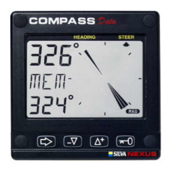
OPERATION Main function Top data is COMPASS HEADING. Top data is either magnetic or true HEADING and your choice is set in the set-up. When magnetic Compass course is selected, the small MAG sign is lit on the LCD. Analogue function Press the MODE button to change from Compass heading to steer reference. -
Page 16: Sub-Functions
OPERATION Sub-functions Select sub-function with UP or DOWN. Information text for the sub-function is displayed. You may also ”park” your favourite function so it will automatically be displayed after power Press MODE and KEY together to ”park” the displayed function. The display will flash once to confirm that you have ”parked”... -
Page 17: Advanced Use Of (Str) Mem
AWA, you will need either a Wind Data instrument, or a NEXUS Server with a wind transducer. For the [BTW] and [CTS] functions you will need a NEXUS GPS or any NMEA GPS ,Decca or Loran C navigator to be connected. -
Page 18: Steer Referens [Btw], Option
This steer function will give Compass course, true or magnetic relative bearing to Waypoint. It must be used together with a GPS or Decca/ Loran C navigator connected to the NEXUS network (at the Server or at the GPS instrument). -
Page 19: Tactical Use Of [Mem]
When you are sailing at a good speed and with the sail trimmed, press trim or KEY. The Compass Data will then store the present course in memory MEM as a reference. If you then have a lifter, press TRIM again, but if you have a header more then 5º-10º, tack. -
Page 20: Trip Log [Trp], Option
Miles. 4.5.14 In a small NEXUS network The Compass Data instrument can be used in a small Network together with the Speed log, Multi Repeater or analogue instruments, without a Server. When both the log and Compass transducers are installed at the Compass Data instrument, we recommend you to install by use of the connection kit art.no. - Page 21 When using the Compass Data in a Network with more then 3 transducers, we recommend you to use the Nexus Server. One Nexus power/data cable is used to connect all instruments. You will have NMEA 0183 in/out. Depth information will (if used) be repeated at more than one NEXUS instrument.
-
Page 22: Calibration / Set-Up
5.1.3 C14 Display NAV functions, option NAV functions are only useful when the Compass Data is connected in a Nexus Network with Compass transducer and a navigator. The selection NAV On will add the functions as described under Nexus Network See... -
Page 23: C15 Beep When Key Is Pressed
CALIBRATION 5.1.4 C15 Beep when key is pressed Setting KEY On will make a beep at every key press, and when KEY is OFF. There is no beep. 5.1.5 C16 Referens pointer On/OFF Setting REF On will show a reference pointer in the true direction as a steer indicator in the Compass graphical mode. -
Page 24: C23 Unit For Temperature
CALIBRATION If the Compass Data is installed with Nexus Server where the log is already calibrated, no further calibration is needed. 5.2.3 C23 Unit for temperature 5.2.4 Select degree Celsius [C] or degree Fahrenheit [F]. 5.2.5 C24 Temperature offset By adding a positive or [-] negative value here, it will be added as an offset before displayed as the temperature. -
Page 25: C35 Clear The Autodeviation
CALIBRATION you may (or not) take the boat the opposite direction as when Autodeviated. The text [CHK] starts flashing and a pointer will show you the course where to end. When you have taken the boat through the minimum 360 turn, press KEY again, and if successful, the text [CHK Atd] will appear again, otherwise, ERR 17 or ERR 19 will appear, i.e. -
Page 26: C69 Pitch Adjustment
C70 Configure Nexus To return to normal mode, press KEY when the text [rET] is displayed. In the configuration you will be able to tell the Nexus Network where you have installed the log and wind transducer. This is important because you may optionally install those transducers at the Server instead of the instrument. -
Page 27: Connection Of Trim Button
Network. To be able to set both steer and trim reference, the optimum way is to connect one trim button for speed to the Compass Data instrument and one trim button for steer at the Server. Such an installation gives you the opportunity to trim both speed and steer with separate buttons. -
Page 28: Maintenance And Fault Finding
Fault finding Before you contact your Nexus dealer, and to assist your dealer to give you a better service, please check the following points and make a list of: All connected instrument and transducers, including their software versions. -
Page 29: Error Messages
Remote command that can not be performed. ERR 17 Too small magnetic variation. ERR 18 Busy with Autodeviation ERR 19 Autodeviation check error, repeat again. If other messages than the above appears on the Compass Data instrument, contact your Nexus dealer. -
Page 30: Specifications
9600 baud. User policy: The Nexus network is open for new users and applications without a licence or licence fee. The easy link between Nexus network and your PC-application is the full duplex PC interface (Art. No. 21248). The interface comes with software and is supplied with a 9- pole D-sub connector cable for the RS232 PC port. -
Page 31: Optional Accessories
(10 + 26 ft) cable 20721 Mast top Unit, 22 m ( 72 ft) cable 20860 Fluxgate Compass, 8 m (26 ft) cable 21000 GPS Antenna, Nexus/NMEA, fix, 10 m ( 33 ft) cable 21117 GPS Compass XL1000, portable 21170 GPS Navigator XL300, portable... - Page 32 Single bracket for Maxi repeater 69999 Double bracket for Maxi repeater 21248 Nexus FD interface. PC interface with 1 m (3.3 ft) cable. Includes a 3½”disc. with software for Waypoint editing and a data bus manager and NMEA interface 19763...
-
Page 33: Abbreviations
ABREVIATIONS Abbreviations ADJust Apparent Apparent Wind Angle Apparent Wind Speed BATtery Boat SPeed Bearing To Waypoint Celsius CALibration CONfiguration DEMonstration mode Fahrenheit Heading KiloMetre KnoTS Liquid Crystal Display MAGnitic Miles per Hour Mixture NAVigation NeXT leg RETurn SEA dampening Speed Over Ground STAtic TeMPerature TRiM... -
Page 34: Warranty
WARRANTY WARRANTY GENERAL All our products are designed and built to comply to the highest class industry standards. If the products are correctly installed, maintained and operated, as described in the installation and operation manual, they will provide long and reliable service. Our international Network of distributors can provide you with the information and assistance you may require virtually anywhere in the world. -
Page 35: Warranty Card
WARRANTY File id: WARRANTY CARD TO BE RETURNED TO YOUR NATIONAL DISTRIBUTOR OWNER: Name: Street : City/Zip Code : Country: Product name: Serial number: Date of purchase: _________________________Date installed ______________________________ Dealers stamp: Tick here if you do not wish to receive news about future products...
Need help?
Do you have a question about the Compass Data and is the answer not in the manual?
Questions and answers