Nexus NX2 Installation And Operation Manual
Hide thumbs
Also See for NX2:
- Installation and operation manual (64 pages) ,
- Installation manual (28 pages) ,
- Installation and operation manual (68 pages)

Related Manuals for Nexus NX2


Summary of Contents for Nexus NX2
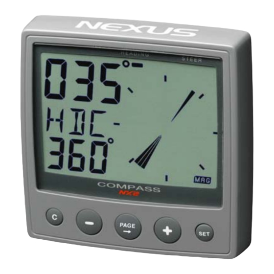
- Page 1 Compass - Instrument - Installation and Operation Manual Installation and Operation Manual English English...
- Page 2 COMPASS...
- Page 3 If the instrument are to be used in a Nexus Network, there are some systems settings that are dependent on where the transducers are installed, i.e. at the instrument or at the Server.
-
Page 4: Table Of Contents
Connections in Nexus Network..............10 2.1.3 Connection of log transducer ..............10 First start...................12 Initialising the instrument in a Nexus Network..........12 Re-initialising the instrument................ 12 Operation ..................13 About this manual ..................13 How to use the 4 push-buttons ..............14 4.2.1... - Page 5 Maintenance and fault finding ..........30 Maintenance....................30 Fault finding....................30 6.2.1 General ....................30 6.2.2 Fault - action ....................30 6.2.3 Error messages..................31 Specifications ................32 Technical specifications ................32 Nexus Network introduction and user policy..........32 Optional Accessories .............. 33 Abbreviations................35 Warranty ................... 36 Warranty ......................36...
-
Page 6: Part Specifications
COMPASS Part specifications NX2 Compass Data is delivered with all parts for mounting. Check prior to installation. Compass Data instrument Qty. Description Reference Instrument, NX2 Compass Data Instrument front cover Drill template Installation and user manual Warranty card Pin bolts for instrument mounting... - Page 7 COMPASS...
-
Page 8: Installation
By using the connection kit when both log and compass transducers are installed with a single cable to the NX2 Compass instrument. • The installation may also include a NX2 Server where all transducers may be connected. All data including power will pass along one cable. •... -
Page 9: Installing The Instrument
Run the Nexus Network cable from the Server to the instrument. • If you want to cut the Nexus Network cable to length, disconnect 4-pole jack plug and cut the cable. Peel off about 35 mm (1,4") of the cable insulation. Remove about 6 mm (1/4") from the 3 isolated wires (the 4th wire is an earth / screen). - Page 10 COMPASS • Apply silicon paste to the instrument connection pins at the back of the instrument. Press the jack plug onto the instrument pins. Press the cable in to the cable leads. • Mount the connection back cover with the screw. Your instrument installation is done!
-
Page 11: Installing Cable
3A Fuse 2.1.2 Connections in Nexus Network If you already have a Nexus Network i.e. a Server, it is more practical to connect the transducer to the Server due to the single instrument cable installation. Note, Set C71 OFF (see 5.4.1). - Page 12 COMPASS If you have another log instrument i.e. a NX2 Log, Nexus log, a Star log, a D-20 log, a 2200 log or a 220 log, you may connect the single log pulse wire from that instrument to the Compass Data instrument terminal 4.
-
Page 13: First Start
ID when the Compass transducer is connected direct at the instrument and the setting in C71 is on (default setting). Initialising the instrument in a Nexus Network At the first power on after installation, you will be asked to press SET [PrSKEY]. -
Page 14: Operation
COMPASS Operation About this manual • Each time a push-button is referred to in this manual, the push- button name will appear in bold and CAPITAL letters, e.g. PAGE. • Unless otherwise stated, the push-button presses are momentary. • Each time a function is mentioned in the text, it will be in brackets and in the same format, where possible, as displayed, e.g. -
Page 15: How To Use The 4 Push-Buttons
COMPASS How to use the 4 push-buttons COMPASS HEADING COURSE or STEER information INFOTEXT SUB- FUNCTION CLEAR PLUS PAGE DOWN 4.2.1 PAGE A press on PAGE, changes the mode page of the graphical display. It scrolls in a circular pattern, one step for every press. The PAGE button is also used to move the cursor when in edit mode. -
Page 16: Clear
To select between the 4 light levels, press UP: [LOW], [MED], [MAX] and [OFF]. To lock the selected level, press SET. The selected light level will be copied to all NX2 instruments connected to the system. When the lighting is on, it is not possible... -
Page 17: Main Function
COMPASS Main function Top data is COMPASS HEADING. Top data is either magnetic or true HEADING and your choice is set in the set-up. When magnetic Compass course is selected, the small MAG sign is lit on the LCD. Analogue function Press the PAGE button to change from Compass heading to steer reference. -
Page 18: Sub-Functions
COMPASS Sub-functions Select sub-function with PLUS or DOWN. Information text for the sub-function is displayed. You may also ”park” your favourite function so it will automatically be displayed after power on. Press PAGE and SET together to ”park” the displayed function. The display will flash once to confirm that you have ”parked”... -
Page 19: Advanced Use Of (Str) Mem
You may also use one or more external TRIM buttons to set new references. To be able to utilise the wind steer function AWA, you will need either a Wind Data instrument, or a NX2 Server with a wind transducer. For the [BTW] and [CTS] functions you will need a NX2 GPS or any NMEA GPS ,Decca or Loran C navigator to be connected. -
Page 20: Steer Referens [Btw], Option
NX2 Autopilot is installed (and activated for wind steering). Use the PLUS and MINUS to change the direction of the WA pointer, then press SET. Your NX2 Autopilot, if activated in wind mode, will now perform an automatic tack. 4.5.5 Steer referens [BTW], option The text [OFF] or [MEM] is displayed. -
Page 21: Tactical Use Of [Mem]
COMPASS 4.5.7 Tactical use of [MEM] Function [MEM] is used to discover the smallest of wind shifts during upwind or downwind sailing, but it is your tactical decision wheter to tac or to stay on course. The Compass Data instrument will automatically keep track on wheter you are using the starboard or port MEM if the course difference between each trim is more then 45º. -
Page 22: 4.5.10 Trip Log [Trp], Option
4.5.11 Water temperature [TMP], option The text [TMP] is displayed with water temperature in Celsius or Fahrenheit. This function requires a NX2, Nexus or Star log transducer. 4.5.12 Dead reckoning [CMG / DMG] This function requires both Compass and Log transducers. - Page 23 COMPASS When using the Compass Data in a Network with more then 3 transducers, we recommend you to use the NX2 Server. One Nexus Network power/data cable is used to connect all instruments. You will have NMEA 0183 in/out. Depth information will (if used) be repeated at more than one NX2 instrument.
-
Page 24: Calibration / Set-Up
C20 - C24 = BSP, Log transducer and temp calibrations. C30 - C37 = HDC, Compass settings. C70 - C74 = CON, Configuration of the NX2 system. To change a calibration value, press SET. To select calibration value, press DOWN, PLUS and PAGE as required. -
Page 25: C15 Beep When Key Is Pressed
If you suspect a current in the water, drive the boat in both directions and divide trip counter distance by two. If the Compass Data is installed with NX2 Server where the log is already calibrated, no further calibration is needed. -
Page 26: C23 Unit For Temperature
COMPASS 5.2.3 C23 Unit for temperature Select degree Celsius [C] or degree Fahrenheit [F]. 5.2.4 C24 Temperature offset By adding a positive or [-] negative value here, it will be added as an offset before displayed as the temperature. C30 Compass Settings To return to normal mode, press SET when the text [rET] is displayed. -
Page 27: C35 Clear The Autodeviation
COMPASS The text [CHK] starts flashing and a pointer will show you the course where to end. When you have taken the boat through the minimum 360° turn, press SET again, and if successful, the text [CHK Atd] will appear again, otherwise, ERR 17 or ERR 19 will appear, i.e. the difference between the last Autodeviation and this Autocheck is to big to be accepted. -
Page 28: C69 Pitch Adjustment
COMPASS the boat is horizontal. By entering a minus sign [-] in front of the value the roll will be decreased by the value. When the offset is without a minus sign, it will be added. When a roll transducer is connected, both wind speed and wind angle will be compensated for the roll and thus increasing the accuracy. -
Page 29: C70 Configure Nx2
To return to normal mode, press SET when the text [rET] is displayed. In the configuration you will be able to tell the Nexus Network where have installed the log and wind transducer. This is important because you may optionally install those transducers at the Server instead of the instrument. -
Page 30: Connection Of Trim Button
COMPASS 5.4.4 Connection of trim button Connect the trim button as per the drawing. The button should make a short connection when pressed. It is also possible to connect more than one button in parallel, for example one on starboard and one on port side. Article number for the push button:19763. -
Page 31: Maintenance And Fault Finding
Fault finding Before you contact your NX2 dealer, and to assist your dealer to give you a better service, please check the following points and make a list of: •... -
Page 32: Error Messages
6.2.3 Error messages The following messages may appear on the display: ERR 2 Nexus Network is missing, check colour coded connections ERR 3 No Network data received within a given time. ERR 10 Range error caused by incorrectly entered value, e.g. 430°. -
Page 33: Specifications
9-pole D-sub connector cable for the RS232 PC port. The PC interface will be a very useful tool to control and monitor real time data, or when editing Waypoints to/from PC- file or to/from NX2 GPS or Server. For users who writes there own software, please contact SILVA SWEDEN and ask for NX2 Application notes. -
Page 34: Optional Accessories
COMPASS Optional Accessories Below find a selection of optional accessories available. Please contact your local NX2 dealer for more information. NX2 Completes 22118-3 Multi Control instrument and Server, 8m cable 22118-2 Multi Control and Server with Speed Log and depth transducer, 8m cable... - Page 35 Multi XL instrument, 4m cable (RCI or Multi Center needed to control Multi XL) 21684-1 Multi XL Set, Multi XL instrument and Remote Control instrument 69995 Mast bracket XL, in aluminium for Multi XL and Nexus / Star 110x110mm instr. NX2 GPS 22118-6 GPS Navigator, with GPS Antenna, 8+10m cable...
-
Page 36: Abbreviations
COMPASS Abbreviations ADJust Apparent Apparent Wind Angle Apparent Wind Speed BATtery Boat SPeed Bearing To Waypoint Celsius CALibration CONfiguration DEMonstration mode Fahrenheit Heading KiloMetre KnoTS Liquid Crystal Display MAGnitic Miles per Hour Mixture NAVigation NeXT leg RETurn SEA dampening Speed Over Ground STAtic TeMPerature TRiM... -
Page 37: 10 Warranty
COMPASS 10 Warranty... - Page 38 COMPASS...
- Page 39 COMPASS...
- Page 40 COMPASS Copyright ©: Nexus Marine AB Kuskvägen 4, 191 62 Sollentuna, Sweden Tel: +46 -(0) 8 – 506 939 00. Fax: +46 -(0) 8 -506 939 01 www.nexusmarine.se...
Need help?
Do you have a question about the NX2 and is the answer not in the manual?
Questions and answers