Advertisement
Available languages
Available languages
Quick Links
Advertisement

Related Manuals for BST TRAINY CD


Summary of Contents for BST TRAINY CD
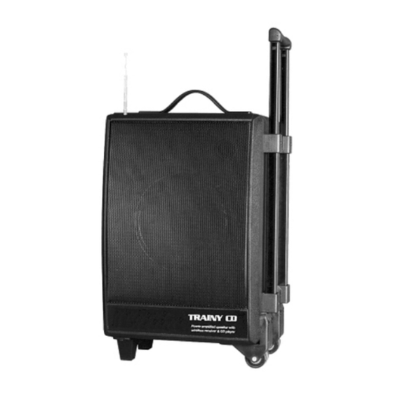
- Page 1 TRAINY CD Enceinte VHF & USB amplifiée VHF & USB amplified speaker MODE D’EMPLOI USER MANUAL...
- Page 2 FRANÇAIS IMPORTANT L'emploi de contrôles ou ajustements ou utilisations autres que celles indiquées peuvent provoquer une exposition aux radiations. 4. ROULETTES DESCRIPTION : 5. EMBASE POUR PIED D’ENCEINTE 1. POIGNEES 6. PIEDS Poignées plastiques supérieure 2. CHARIOT 7. MODULE CD/USB Pour dépliez le chariot, tirez sur la poignée jusqu’à...
- Page 3 DESCRIPTION MODULE DE CONTROLE : Vérifiez que la fréquence du micro correspond à celle du 1. INDICATEUR POWER récepteur Quand la tension des batteries est bonne, ce voyant s’allume en 11. REGLAGE NIVEAU MIC 2 vert. Si la tension est basse, le voyant s’allume en rouge. Vous devez alors recharger les batteries Utilisez pour ajuster le niveau de sortie du micro connecteur sur Note : Meme si vous n’utilisez pas souvent le trainy, vous devez le...
- Page 4 MODULE CD ET TELECOMMANDE : 1. FENTE D’INSERTION DU CD ( MODULE & TELECOMMANDE ) 10. BOUTON FOLDER DOWN ( MODULE & TELECOMMANDE ) Insérez votre cd ( etiquette vers le haut ) dans cette fente. Utilisez cette touche pour changer de répertoire de lecture L’insertion se fera automatiquement.
- Page 5 Micro Main : 1. GRILLE + CELLULE 2. INDICATEUR POWER Cet indicateur s’allume lorsque vous allumez le micro 3. INDICATEUR BATTERIE Cette led vous indique l’état de la pile. A l’allumage, la led s’allume puis s’éteint. Si cette dernière reste allumé alors la pile est HS et vous devez la changer .
-
Page 6: Caracteristiques Techniques
Durant la période sous garantie, tout matériel défectueux doit nous être retourné dans son emballage d’origine sous colis pré-payé. BST vous retournera vos biens par colis pré-payé au cours de l’année de garantie. Au-delà, les frais d’expédition seront à la charge du client. - Page 7 ENGLISH 3. METAL GRILL 4. WHEELS IMPORTANT 5. POLE MOUNT Use of controls or adjustments or performance of 6. FOOT STANDS procedures other than those specified herein may 7. CD / USB MODULE result in hazardous radiation exposure. See description later DESCRIPTION 8.
- Page 8 CONTROL BOARD DESCRIPTION : 1. POWER LED 12. MIC 3 INPUT When voltage is high, it lights green; When voltage is low, it lights Can be used to connect a microphone. Adjust the level by using red. the potentiometer (13) 2.
- Page 9 USB / CD MODULE & REMOTE CONTROL DESCRIPTION : Skip the starting play folder to previous folder during stop mode. 1. CD INPUT In program entry mode : Insert your CD in this part. Change the file for program select to previous folder’s first file 2.
- Page 10 HANDHELD MICROPHONE DESCRIPTION : 1. MESH 2. POWER LED INDICATOR When you switch your microphone on, the LED will light. 3. LOW BATTERY LED INDICATOR This LED shows you the operating level of the battery. When you switch your microphone on, the LED lights on for a fast moment then lights off.
-
Page 11: Specifications
During warranty period, defective equipment must be sent by pre-paid mail in the original box. BST will return the goods by pre-paid mail during the first year of warranty; thereafter the mailing cost is to be paid by the recipient Potentiometers have a limited lifetime and are not covered by the manufacturer for more than normal use.
Need help?
Do you have a question about the TRAINY CD and is the answer not in the manual?
Questions and answers