Table of Contents
Advertisement
AGA-HEARTLAND | 1050 FOUNTAIN STREET NORTH | CAMBRIDGE, ON N3H4R7 | CANADA
PHONE. (877) 650-5775 | FAX. (519) 650-3773 | WWW.HEARTLANDAPP.COM | WWW.AGA-
RANGES.COM
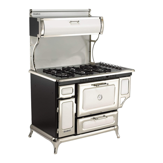
MODEL 9200/7200 GAS RANGE
Installation and Operating Instructions
Model 9200 Model 7200
Note: Please read these instructions thoroughly before attempting to install this unit.
Save these instructions for future use.
ATTENTION INSTALLER: Leave this manual with appliance.
These symbols on the name plate mean the product has been
design certified by American Gas Association Laboratories and
Canadian Gas Association Laboratories.
Manual #7302
© 2007 AGA-HEARTLAND
REV 100507
Advertisement
Table of Contents
Troubleshooting

Related Manuals for Heartland 9200/7200


Summary of Contents for Heartland 9200/7200
- Page 1 AGA-HEARTLAND | 1050 FOUNTAIN STREET NORTH | CAMBRIDGE, ON N3H4R7 | CANADA PHONE. (877) 650-5775 | FAX. (519) 650-3773 | WWW.HEARTLANDAPP.COM | WWW.AGA- RANGES.COM MODEL 9200/7200 GAS RANGE Installation and Operating Instructions Model 9200 Model 7200 Note: Please read these instructions thoroughly before attempting to install this unit.
-
Page 2: For Your Safety
* Do not attempt to extinguish a grease fire with water. Cover grease fires with a pot lid or bak- ing soda. * Avoid the use of aerosol containers near the range. * Never place pans, cookie sheets or roasters directly on the oven bottom -use the rack in its lowest position. - Page 3 If the information in this manual is not followed exactly, a fire or explosion may result causing property damage, personal injury or death. • Do not try to light any appliance. • Do not touch any electrical switch; do not use any phone in your building. •...
-
Page 4: Consumer Warranty
Gas Models 9200/7200 ENTIRE PRODUCT – LIMITED ONE YEAR WARRANTY AGA-HEARTLAND warrants the replacement or repair of all parts, including gas components of this stove which prove to be defective in material or workmanship, with the exception of the painted or porcelain enamel finish or plated sur- faces, for one year from the date of original purchase. -
Page 5: Table Of Contents
TABLE OF CONTENTS 1. Assembly of Exhaust Hood to Range 2. Positioning the Range 3. Electrical Installation 4. Exhaust Hood 5. Ventless Installation 6. Vented Installation 7. Installation of Ducting 8. Venting Safety Guidelines 9. Gas Line Installation 10. Clearances Diagrams 11. -
Page 6: Assembly Of Exhaust Hood To Range
4. Put both hands on the trim and carefully push the range into place, make sure floor is clear of all debris. Don't forget to plug in the main power cord and the exhaust hood power cable before the range is in its final position. -
Page 7: Electrical Installation
Exhaust Hood Electrical Connection After your exhaust hood has been installed the very last thing to do is to connect the special plug to the range. The female receptacle for the exhaust hood is located at the rear of the stove by the main power (male) receptacle (See page 10 for receptacle locations and figure 4 for receptacle illustration). -
Page 8: Exhaust Hood
Exhaust Hood Your range is equipped with a two speed range hood that may be either vented directly to the outside, or may be installed ventless. A set of exhaust filters are included with your hood. The filters should be cleaned periodically in soapy water. -
Page 9: Installation Of Ducting
Remove air deflector (used for ventless operation only). Cut appropriate-sized hole through the wall directly behind the range hood outlet (see Figure 5, page 9), making sure no wall studs are cut. Push range into position. From outside of the house, measure distance from the siding to the range outlet. Cut duct pipe that length, plus 1" (25mm) for overlap into outlet. -
Page 10: Venting Safety Guidelines
Gas Line Installation The Model 7200 / 9200 are set for natural gas (NG) OR propane (LP) gas at the factory. Be sure your range is cor- rectly installed by a qualified service techician or installer for the type of gas on which it is to be used. -
Page 11: Clearances Diagrams
• Top of counter to underside adjacent cabinetry: 18” (46 cm) • Cooktop to underside overhead cabinets: 30-1/4” (77 cm) • Edge of range to combustible wall on either side: 6” (15 cm) • Cut out width for range’s main body: 30” (76 cm) •... - Page 12 (111 cm) with oven 0” clearance door open 52” (133 cm) with bottom drawer fully open Range Hood Outlet 3-1/2” x 10-1/2” (8.9 cm x 26.7 cm) (6” clearance to any com- bustible side wall) 6” (16 cm) 3-7/8” (10 cm) 24”...
- Page 13 • Top of counter to underside adjacent cabinetry: 18” (46 cm) • Cooktop to underside overhead cabinets: 30-1/4” (77 cm) • Edge of range to combustible wall on either side: 6” (15 cm) • Cut out width for range’s main body: 48-1/2” (123 cm) •...
- Page 14 (29 cm) (96 cm) Panel 62-3/8” (159 cm) 39-3/4” 28” (101 cm) (72 cm) Rough in Range Hood Outlet Measurements 3-1/2” x 10-1/2” (8.9 cm x 26.7 cm) min 18” min 36” (91.4 cm) Model 7200 Range Hood Outlet 3-1/4” x 10”...
-
Page 15: Important Safety Instructions
5. User servicing—do not repair or replace any part of the appliance unless specifically recommended in the manual. All other servicing should be referred to a qualified technician. 6. Storage in or on appliance—flammable materials should not be stored in an oven, near surface units or in range cabinet. -
Page 16: Features
Figure 13 Cooking Controls The cooking controls are located on the right hand side of the cooktop; these controls offer an infinite number of heat settings for ease and accuracy in cooking and baking. Sealed Burner Features (see fig. 13) A) Centre Burners - are two maximum 8,000 BTU (2.34 kW)(L/P 7,000 BTU) with simmer of 600 BTU (.2 kW) sealed gas burners, easy clean, for medium duty cooking tasks. -
Page 17: Oven Features
Figure 14 Oven Features E) Oven Temperature Control - With infinite bake temperature and broil control. All units feature "auto gas shutoff", which means that if for any reason the flame goes out, gas to the oven burner shuts off! F) Gas Oven Features: -4 position racking -3.6 cubic feet of energy efficient area -16,500 BTU (4.83Kw) oven burner... -
Page 18: Control Panel Layout
The control panel is laid out in a straight line and each control is identified by a graphic on the right side of the knob. Model 7200 Control Panel Left Rear Burner Control (Medium) Left Front Burner Control (Large) Centre Rear Burner Control (Medium) Centre Front Burner Control (Medium) -
Page 19: Operation
Lighting the Top Burners Your range is equipped with a spark ignition system that is electrically operated. You need only to push in and turn the knob to any position and the burner will light. When you turn the knob, you will hear a distinct clicking noise. After the burner lights, the clicking noise will stop. -
Page 20: Oven Cooking & Lighting
Wait at least 1 minute before trying to light oven again. If you are still not successful see "trouble shooting guide". Range Thermostat The temperature in the oven is transmitted to the thermostat by the sensor tube located at the rear of the oven. -
Page 21: Power Failure Operation
Power Failure Operation If electrical power is interrupted in your area, you can still cook meals on your Heartland gas range. By following these simple directions you will be able to use the burners and oven without the benefit of electricity. -
Page 22: Clock/Timer
Minute Minder Bell symbol indicates minute minder in operation Functions: Power on Display is flashing Set time of day Press left button" ". Set time of day with " and " " buttons. This function remains activated for 7 seconds after the last " Set minute minder This function is permanently activated and can be immediately set with "... -
Page 23: Cooking Guide
Cooking Guide Heartland 7200/ 9200 Cooking Guide Meat Roasting Guide Food Whole Chicken Chicken Wings Fish Roast Lamb Turkey - unstuffed Turkey - stuffed Broiling Guide Food Steak Chicken Breast Pork Chops These times are approximate and should be used in conjunction with a properly placed meat thermometer. -
Page 24: Care And Cleaning
Clean porcelain surfaces, using warm soapy water, glass cleaner or non-abrasive cleaner and a soft cloth. Avoid abrasive cleaners. If any acid-based food or liquid, such as lemon juice or tomato juice is spilled on the range wipe it at once to prevent staining. -
Page 25: Oven Cleaning
Oven Cleaning Your range must be kept clean and free of accumulations of grease or spillovers which may ignite. This is most important in the oven and broiling compartment. When cleaning the oven, make sure it is turned “Off” and is cool. For simple spills, clean the oven with a strong solu- tion of detergent, then wipe with a clean damp cloth and dry. -
Page 26: Nickel Trim
Nickel-Plated Trim Nickel must be cleaned with warm soapy water and a mirco cloth. If any acid-based food or liquid, such as lemon juice or tomato juice, is spilled on the range, wipe it at once to prevent staining. Exhaust Hood Exhaust filters are included with your exhaust hood. -
Page 27: Interior Oven Rack Removal
Interior Oven Rack The oven rack is designed with stop-locks so that when placed correctly on the supports, it (a) will stop before coming completely out of the oven, (b) will not tip when placing or removing food. To install, place the rack "feet" on the rack support and push the oven rack backward along the rack support. -
Page 28: Removal Of Oven Door
3) The door weighs about 25 lbs (11 kg), so exercise caution when removing the door. 4) To replace the door reverse this sequence. WARNING! Do not sit, lean, lift or stand on the doors or drawers of this range as pos- sible injuries may result. Make sure the brass catch is securely hinged... -
Page 29: Broiling
Broiling Broiling is cooking by direct radiated heat from above the food. It is fast because no preheat time is required and the food is close to the burner. When broiling, the oven control knob should be set to the broil symbol or the 500°F (265°C) setting on the knob. -
Page 30: Setup And Troubleshooting
Filters Splashback Burner Setup & Adjustment The range was carefully set up and inspected at the factory but some final adjustments may be nec- essary once the unit is installed. You should check the following: i) First check to make sure there are no gas leaks. Propane and natural gas have a very distinct smell which is easily detected by the human nose. -
Page 31: Air Shutter Adjustment
These two items must be checked before putting the appli- ance into operation. (see figure 31) NOTE: Before putting the 7200 /9200 Gas Range into service, be sure that all the setup procedures recommended in this manual have been completed. -
Page 32: Troubleshooting Guide
Check positioning of shrink sleeving on receptacle - should be flush with end of receptacle - trim if necessary. Replace module. Check ground/earth connection of range chassis and ground/earth lead connection to module. Use smaller sized pots or reduce size of flame. Do not use griddle plate directly over top of grates. -
Page 33: Conversion Kits And Information
Normally, Model 7200 and 9200 are ordered from the factory preset for either Natural Gas or Liquid Propane. However, they can be converted after installation by performing a conversion procedure to the gas components with the appropriate conversion kit. The components requiring conversion are, 1) the pressure regulator, 2) top burner controls, 3)oven burner control,... -
Page 34: Products
Metro 3825 and Legend 3820 models are available. 9730 (Built-in)- Dual oven, one convection, one standard radiant, and self clean oven feature. 4210- 30" Gas / Electric kitchen range - 4 sealed gas burn- ers, self clean oven feature, electric convection oven fits in a 30" opening! -
Page 35: Parts Diagram
1599 1592 60283 60287 1556 60286 7374 60226 60504 60243 60277 60502 1125 60238 60503 60241 60250 60251 60501 60277 1110 60237 1599 80131 1592 80138 80132 1556 80141 7374 80128 60504 60277 1125 60238 60237 1110 60501 80151 60250 60277 7200/9200 Parts Diagram 1596... -
Page 36: Parts List
7599 Manifold Weldment (9200 only) 7720 Oven Bottom Pan 7793 Manifold Weldment (7200 only) 7795 Oven Burner 7797 Oven Rack Model 7200/9200 Range Parts List 8200 Light Socket & Housing 8204 Oven Lens 9237 Electronic Minute Minder 60501 Warming Drawer Frame... -
Page 37: Rating Plate
Serial HLG00001 Model 7200/9200 Serial No. HLG00001 Natural Gas Medium 8000 BTU/HR Large 10000 BTU/HR Oven 16500 BTU/HR Manifold Pressure 5 IN. W.C. Power Requirements 120 Volt 3 amps. 60 Hz This appliance can be used with LP/Propane gas and Natural gas. The gas appliance regulator must be set for the gas with which the appliance is used. -
Page 38: Wiring Diagrams
Wiring Diagrams Technical Data 7200 WIRING DIAGRAM - N.A. - Voltage 120 v / 60 Hz - Load 3 amps (model 9200) - Load 3 amps (model 7200) Fan/Clock NOTE: Service amperage should be calculated by a qualified elec- trician. The maximum propane/natural gas supply inlet must not exceed 14 inches of water column.
Need help?
Do you have a question about the 9200/7200 and is the answer not in the manual?
Questions and answers