HP Pavilion dv4000 Maintenance And Service Manual
Notebook pc
Hide thumbs
Also See for Pavilion dv4000:
- Hardware and software manual (189 pages) ,
- Information manual (6 pages) ,
- Maintenance and service manual (273 pages)
Table of Contents
Advertisement
Quick Links
Maintenance and Service
Guide
HP Pavilion dv4000 Notebook PC
Compaq Presario V4000 Notebook PC
Document Part Number: 377367-002
August 2005
This guide is a troubleshooting reference used for maintaining
and servicing the notebook. It provides comprehensive
information on identifying notebook features, components, and
spare parts; troubleshooting notebook problems; and performing
notebook disassembly procedures.
Advertisement
Table of Contents
Troubleshooting

Related Manuals for HP Pavilion dv4000


Summary of Contents for HP Pavilion dv4000
- Page 1 Maintenance and Service Guide HP Pavilion dv4000 Notebook PC Compaq Presario V4000 Notebook PC Document Part Number: 377367-002 August 2005 This guide is a troubleshooting reference used for maintaining and servicing the notebook. It provides comprehensive information on identifying notebook features, components, and spare parts;...
- Page 2 The information contained herein is subject to change without notice. The only warranties for HP products and services are set forth in the express warranty statements accompanying such products and services. Nothing herein should be construed as constituting an additional warranty. HP shall not be liable for technical or editorial errors or omissions contained herein.
-
Page 3: Table Of Contents
Contents 1 Product Description 1.1 Features ........1–2 1.2 Resetting the Notebook . - Page 4 3.3 Display Assembly Subcomponents... . . 3–12 HP Pavilion dv4000 Models ....3–12 3.4 Display Assembly Subcomponents.
- Page 5 Contents 5 Removal and Replacement Procedures 5.1 Serial Number ......5–1 5.2 Disassembly Sequence Chart .
-
Page 6: Specifications
Contents 6 Specifications A Connector Pin Assignments B Power Cord Set Requirements Screw Listing D Display Component Recycling Index Maintenance and Service Guide... -
Page 7: Product Description
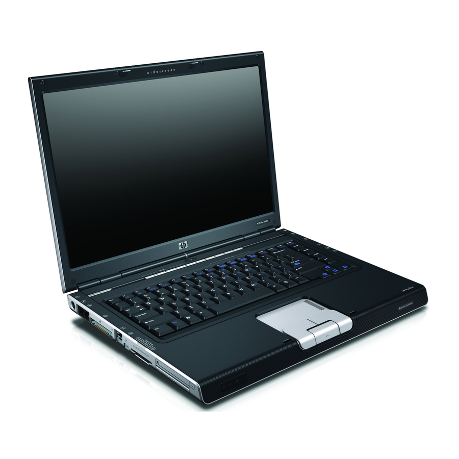
Product Description The HP Pavilion dv4000 Notebook PC 1 and Compaq Presario V4000 Notebook PC 2 offer advanced modularity, Intel® Pentium® M and Celeron® M processors, and extensive multimedia support. HP Pavilion dv4000 Notebook PC and Compaq Presario V4000 Notebook PC Maintenance and Service Guide 1–1... -
Page 8: Features
Product Description 1.1 Features ■ Intel Pentium M 2.00-, 1.73-, 1.60-, or 1.50-GHz processors, or Intel Celeron M 1.50-, 1.40-, or 1.30-GHz processors, varying by notebook model ■ 15.4-inch, WXGA, TFT (1280 × 800) with BrightView display, or 15.4-inch, WXGA, TFT (1280 × 800) display, varying by notebook model ■... - Page 9 IEEE 1394 port ■ Infrared port ■ Quick Launch buttons (HP Pavilion dv4000 models only) A notebook model is considered to be defeatured if it has only 2 Universal Serial Bus ports and none of the components listed above. ■...
-
Page 10: Resetting The Notebook
Product Description 1.2 Resetting the Notebook If the notebook you are servicing has an unknown password, follow these steps to clear the password. These steps also clear CMOS: 1. Enter an incorrect password and press enter 2. Repeat step 1 2 times. After the third entry of the incorrect password, the notebook responds with a “System Disabled”... -
Page 11: External Components
Product Description 1.4 External Components The external components on the front of the notebook are shown below and described in Table 1-1. Depending on your notebook model, component locations may vary. Front Components Table 1-1 Front Components Item Component Function ■... - Page 12 Product Description The external components on the right side of the HP Pavilion dv4000 are shown below and described in Table 1-2. Depending on your notebook model, component locations may vary. Right-Side Components, HP Pavilion dv4000 1–6 Maintenance and Service Guide...
- Page 13 Product Description Table 1-2 Right-Side Components, HP Pavilion dv4000 Item Component Function Optical drive Supports an optical disc, such as a CD or DVD. Audio-out Connects an optional headphone or (headphone) jack powered stereo speakers. Also connects (full-featured the audio function of an audio/video device, models only) such as a television or VCR.
- Page 14 Product Description The external components on the right side of the Compaq Presario V4000 are shown below and described in Table 1-3. Depending on your notebook model, component locations may vary. Right-Side Components, Compaq Presario V4000 1–8 Maintenance and Service Guide...
- Page 15 Product Description Table 1-3 Right-Side Components, Compaq Presario V4000 Item Component Function Optical drive Supports an optical disc, such as a CD or DVD. Audio-out (headphone) Connects an optional headphone or jack (full-featured powered stereo speakers. Also connects models only) the audio function of an audio/video device, such as a television or VCR.
- Page 16 Product Description The external components on the left side of the HP Pavilion dv4000 are shown below and described in Table 1-4. Depending on your notebook model, component locations may vary. Left-Side Components, HP Pavilion dv4000 Table 1-4 Left-Side Components, HP Pavilion dv4000...
- Page 17 Product Description Table 1-4 Left-Side Components, HP Pavilion dv4000 (Continued) Item Component Function 1394 port (4-pin; Connects an optional 1394a device such as full-featured a scanner, a digital camera, or a digital models only) camcorder. Digital Media Slot Supports the following optional digital...
- Page 18 Product Description The external components on the left side of the Compaq Presario V4000 are shown below and described in Table 1-5. Depending on your notebook model, component locations may vary. Left-Side Components, Compaq Presario V4000 Table 1-5 Left-Side Components, Compaq Presario V4000 Item Component Function...
- Page 19 Product Description Table 1-5 Left-Side Components, Compaq Presario V4000 (Continued) Item Component Function 1394 port (4-pin; Connects an optional 1394a device such as full-featured a scanner, a digital camera, or a digital models only) camcorder. Memory Reader Supports the following optional digital (full-featured cards: SD (Secure Digital) Memory Card, models only)
- Page 20 Product Description The standard keyboard components of the notebook are shown below and described in Table 1-6. Standard Keyboard Components 1–14 Maintenance and Service Guide...
- Page 21 Product Description Table 1-6 Standard Keyboard Components Item Component Function fn key Combines with other keys to perform system tasks as hotkeys. For example, pressing fn+f7 decreases screen brightness. caps lock key Enables caps lock and turns on the caps lock light.
- Page 22 Product Description The top components on HP Pavilion dv4000 models are shown below and described in Table 1-7. Top Components, HP Pavilion dv4000 Models Table 1-7 Top Components, HP Pavilion dv4000 Item Component Function ■ On: Notebook is turned on.
- Page 23 Product Description Table 1-7 Top Components, HP Pavilion dv4000 (Continued) Item Component Function Quick Launch buttons Launch default multimedia, digital imaging, (select models only) or music applications (vary by model). Volume mute button Mutes or restores volume. Wireless light On: One or more internal wireless devices (select models only) have been turned on.
- Page 24 Product Description The top components on Compaq Presario V4000 models are shown below and described in Table 1-8. Top Components, Compaq Presario V4000 Models 1–18 Maintenance and Service Guide...
- Page 25 Product Description Table 1-8 Top Components, Compaq Presario V4000 Models Item Component Function Wireless button Turns the wireless functionality on or off, (select models only) but does not create a wireless connection. ✎ To establish a wireless connection, a wireless network must already be set up.
- Page 26 Product Description The HP Pavilion dv4000 notebook TouchPad components are shown below and described in Table 1-9. TouchPad Components, HP Pavilion dv4000 Table 1-9 TouchPad Components, HP Pavilion dv4000 Item Component Function TouchPad Moves the pointer. Left and right TouchPad...
- Page 27 Product Description The Compaq Presario V4000 notebook TouchPad components are shown below and described in Table 1-10. TouchPad Components, Compaq Presario V4000 Table 1-10 TouchPad Components, Compaq Presario V4000 Item Component Function TouchPad Moves the pointer. TouchPad horizontal Scrolls left or right. scroll zone Left and right TouchPad Function like the left and right buttons on...
-
Page 28: Bottom Components
Product Description The external components on the bottom of the notebook are shown below and described in Table 1-11. Bottom Components Table 1-11 Bottom Components Item Component Function Battery bay Holds a battery pack. Vents (4) Provide airflow to cool internal components. - Page 29 Product Description Table 1-11 Bottom Components (Continued) Item Component Function Optical drive Supports an optical disc, such as a CD or DVD. Labels area Contains the serial number and other information labels. Battery pack release latch Releases a battery pack from the battery bay.
-
Page 30: Design Overview
Product Description 1.5 Design Overview This section presents a design overview of key parts and features of the notebook. Refer to Chapter 3, “Illustrated Parts Catalog,” to identify replacement parts, and Chapter 5, “Removal and Replacement Procedures,” for disassembly steps. The system board provides the following device connections: ■... -
Page 31: Troubleshooting
Troubleshooting Å WARNING: Only authorized technicians trained by HP should repair this equipment. All troubleshooting and repair procedures are detailed to allow only subassembly-/module-level repair. Because of the complexity of the individual boards and subassemblies, do not attempt to make repairs at the component level or modifications to any printed wiring board. -
Page 32: Accessing Computer Setup
Troubleshooting Accessing Computer Setup The information and settings in Computer Setup are accessed from the File, Security, Tools, and Advanced menus. 1. Open Computer Setup by turning on or restarting the notebook. Press while the F10 = Based Setup message is displayed in the lower-left corner of the screen. -
Page 33: Selecting From The File Menu
Troubleshooting 4. To confirm the restoration, press 5. Select File > Save changes and exit, and then follow the instructions on the screen. When the computer restarts, the factory settings are restored, and any identification information you have entered is saved. Selecting from the File Menu Table 2-1 File Menu... -
Page 34: Selecting From The Security Menu
Troubleshooting Selecting from the Security Menu Table 2-2 Security Menu Select To Do This Administrator password Enter, change, or delete an HP Administrator password. Power-on password Enter, change, or delete a power-on password. ■ Password options Enable/Disable stringent security. ■... -
Page 35: Selecting From The Tools Menu
Troubleshooting Selecting from the Tools Menu Table 2-3 Tools Menu Select To Do This HDD Self Test options Run a quick or comprehensive self-test on any hard drive in the system. Battery Information View information about any battery packs in the notebook. -
Page 36: Selecting From The Advanced Menu
Troubleshooting Selecting from the Advanced Menu Table 2-4 Advanced Menu Select To Do This Language (or press f2) Change the Computer Setup language. Boot options ■ Enable/Disable MultiBoot, which sets a startup sequence that can include most bootable devices and media in the system. ■... -
Page 37: Troubleshooting Flowcharts
Troubleshooting 2.2 Troubleshooting Flowcharts Table 2-5 Troubleshooting Flowcharts Overview Flowchart Description “Flowchart 2.1—Initial Troubleshooting” “Flowchart 2.2—No Power, Part 1” “Flowchart 2.3—No Power, Part 2” “Flowchart 2.4—No Power, Part 3” “Flowchart 2.5—No Power, Part 4” “Flowchart 2.6—No Video, Part 1” “Flowchart 2.7—No Video, Part 2” “Flowchart 2.8—Nonfunctioning Docking Device (if applicable)”... - Page 38 Troubleshooting Table 2-5 Troubleshooting Flowcharts Overview (Continued) Flowchart Description 2.14 “Flowchart 2.14—No OS Loading, Optical Drive” 2.15 “Flowchart 2.15—No Audio, Part 1” 2.16 “Flowchart 2.16—No Audio, Part 2” 2.17 “Flowchart 2.17—Nonfunctioning Device” 2.18 “Flowchart 2.18—Nonfunctioning Keyboard” 2.19 “Flowchart 2.19—Nonfunctioning Pointing Device” 2.20 “Flowchart 2.20—No Network/Modem Connection”...
-
Page 39: Flowchart 2.1—Initial Troubleshooting
Troubleshooting Flowchart 2.1—Initial Troubleshooting Begin troubleshooting. Go to Is there “Flowchart power? 2.2—No Power, Part 1.” Check Beeps, LED board, LEDs, or error speaker messages? connections. Go to All drives “Flowchart working? 2.17—Nonfunc- tioning Device.” Go to Is there video? “Flowchart Go to (no boot) -
Page 40: Flowchart 2.2—No Power, Part
Troubleshooting Flowchart 2.2—No Power, Part 1 No power (power LED is off). Remove from docking device (if applicable). Go to Power up Power up Reset “Flowchart on battery on battery power.* 2.3—No Power, power? power? Part 2.” Go to Power up Power up Reset “Flowchart... -
Page 41: Flowchart 2.3—No Power, Part
Troubleshooting Flowchart 2.3—No Power, Part 2 Continued from “Flowchart 2.2—No Power, Part 1.” Visually check for debris in battery socket and clean if necessary. Power on? Done Check battery by recharging it, moving it to another notebook, or replacing it. Replace Power on? power supply... -
Page 42: Flowchart 2.4—No Power, Part
Troubleshooting Flowchart 2.4—No Power, Part 3 Continued from “Flowchart 2.3—No Power, Part 2.” Plug directly into AC outlet. Power LED Done Reseat AC adapter in notebook and at power source. Power on? Done External Internal or Replace external Try different Power outlet external AC AC adapter. -
Page 43: Flowchart 2.5—No Power, Part
Troubleshooting Flowchart 2.5—No Power, Part 4 Continued from “Flowchart 2.4—No Power, Part 3.” Open notebook. Reseat loose Loose or components and damaged boards and parts? replace damaged items. Close notebook and retest. Replace the following items (if applicable). Check Power on? notebook operation after each replacement: 1. -
Page 44: Flowchart 2.6—No Video, Part
Troubleshooting Flowchart 2.6—No Video, Part 1 No video. Docking Device Go to *NOTE: To change from internal to Stand-alone “Flowchart external display, use the hotkey or docking 2.7—No Video, combination. device? Part 2.” Stand-alone Internal or Adjust Video OK? Done external brightness. -
Page 45: Flowchart 2.7—No Video, Part
Troubleshooting Flowchart 2.7—No Video, Part 2 Continued from “Flowchart 2.6—No Video, Part 1.” Remove notebook from docking device, if connected. Adjust Check brightness display of external brightness. monitor. Go to “A” in “Flowchart Video OK? Video OK? Done 2.6—No Video, Part 1.”... - Page 46 Troubleshooting Flowchart 2.8—Nonfunctioning Docking Device (if applicable) Nonfunctioning docking device. Reseat power cord in docking device and power outlet. Check voltage Reinstall setting on docking notebook into device. docking device. Reset monitor cable connector at Docking docking device. Done device operating? Docking device...
-
Page 47: Flowchart 2.9—No Operating System (Os) Loading
Troubleshooting Flowchart 2.9—No Operating System (OS) Loading No OS loading.* Reseat power cord in docking device and power outlet. No OS loading from hard drive, go to “Flowchart 2.10—No OS Loading, Hard Drive, Part 1.” No OS loading from diskette drive, go to “Flowchart 2.13—No OS Loading, Diskette Drive.”... - Page 48 Troubleshooting Flowchart 2.10—No OS Loading, Hard Drive, Part 1 OS not loading from hard drive. Go to “Flowchart Nonsystem 2.11—No OS disk message? Loading, Hard Drive, Part 2.” Reseat external hard drive. OS loading? Done Boot from Go to Boot “Flowchart from 2.13—No OS...
- Page 49 Troubleshooting Flowchart 2.11—No OS Loading, Hard Drive, Part 2 Continued from “Flowchart 2.10—No OS Reseat Loading, hard drive. Hard Drive, Part 1.” 1. Replace Disc or hard drive. diskette in 2. Replace system drive? Hard drive board. Done accessible? Remove disc or diskette and Run FDISK.
- Page 50 Troubleshooting Flowchart 2.12—No OS Loading, Hard Drive, Part 3 Continued from “Flowchart 2.11—No OS Loading, Hard Drive, Part 2.” System Install OS files on hard and reboot. drive? Virus loading from Clean virus. Done hard drive? hard drive? Run SCANDISK and Replace Diagnostics on check for...
-
Page 51: Flowchart 2.13—No Os Loading, Diskette Drive
Troubleshooting Flowchart 2.13—No OS Loading, Diskette Drive OS not loading Reseat Done from diskette drive. loading? diskette drive. Bootable Install bootable Nonsystem diskette diskette and disk message? in drive? reboot notebook. Check diskette for system files. Go to Boot Try different “Flowchart from another diskette. - Page 52 Troubleshooting Flowchart 2.14—No OS Loading, Optical Drive No OS Install bootable Bootable Disc loading from disc and disc in in drive? CD-ROM or reboot drive? DVD-ROM drive. notebook. Install Try another bootable disc. bootable disc. Boots from Done CD or DVD? Boots from Reseat Done...
- Page 53 Troubleshooting Flowchart 2.15—No Audio, Part 1 Turn up audio internally or No audio. Audio? Done externally. Go to Notebook in Internal “Flowchart docking device Undock audio? 2.16—No Audio, (if applicable)? Part 2.” Go to Replace the following docking device “Flowchart components one at a time, as applicable.
- Page 54 Troubleshooting Flowchart 2.16—No Audio, Part 2 Continued from “Flowchart 2.15—No Audio, Part 1.” Audio Reload driver in OS audio drivers. configured? Correct Load drivers and drivers for set configuration application? in OS. Connect to external speaker. Replace audio board and speaker Audio? Audio?
- Page 55 Troubleshooting Flowchart 2.17—Nonfunctioning Device Nonfunctioning device. Reseat device. Unplug the nonfunctioning device from the notebook and inspect cables and plugs for bent or broken pins or other damage. Fix or Clear Any physical replace CMOS. device detected? broken item. Go to “Flowchart Reattach device.
- Page 56 Troubleshooting Flowchart 2.18—Nonfunctioning Keyboard Keyboard not operating properly. Connect notebook to good external keyboard. External Replace device system works? board. Reseat internal keyboard connector (if applicable). Keyboard Replace internal operating keyboard or properly? cable. Keyboard operating Done Done properly? Replace system board.
- Page 57 Troubleshooting Flowchart 2.19—Nonfunctioning Pointing Device Pointing device not operating properly. Connect notebook to good external pointing device. Replace External system device board. works? Reseat internal pointing device connector (if applicable). Replace internal Pointing device pointing device operating or cable. properly? Pointing device Done Done...
- Page 58 Troubleshooting Flowchart 2.20—No Network/Modem Connection No network or modem connection. Network Replace jack or modem jack or have jack active? activated. Connect Digital to nondigital line? line. Network Reload NIC/modem or modem Done drivers and configured connection reconfigure. in OS? working? Disconnect all Replace NIC/modem...
-
Page 59: Illustrated Parts Catalog
Illustrated Parts Catalog This chapter provides an illustrated parts breakdown and a reference for spare part numbers. 3.1 Serial Number Location When ordering parts or requesting information, provide the notebook serial number and model number located on the bottom of the notebook. Serial Number Location Maintenance and Service Guide 3–1... -
Page 60: Notebook Major Components
Illustrated Parts Catalog 3.2 Notebook Major Components Notebook Major Components, HP Pavilion dv4000 3–2 Maintenance and Service Guide... - Page 61 Spare Part Item Description Number Display assemblies (include display cable, wireless antenna boards, and antenna cables) For use with HP Pavilion dv4000 models 15.4-inch, WXGA, TFT with BrightView 383477-001 15.4-inch, WXGA, TFT 383476-001 For use with Compaq Presario V4000 models 15.4-inch, WXGA, TFT with BrightView...
- Page 62 Illustrated Parts Catalog Notebook Major Components, Compaq Presario V4000 3–4 Maintenance and Service Guide...
- Page 63 United Kingdom 384635-031 384635-331 United States 384635-001 The Netherlands Top covers For use with full-featured HP Pavilion dv4000 models 397858-001 (includes TouchPad) For use with defeatured HP Pavilion dv4000 models 397860-001 (includes TouchPad) For use with full-featured Compaq Presario V4000...
- Page 64 Illustrated Parts Catalog Notebook Major Components, HP Pavilion dv4000 3–6 Maintenance and Service Guide...
- Page 65 Spare Parts: Notebook Major Components (Continued) Spare Part Item Description Number Miscellaneous Doors/Covers Kit For use with HP Pavilion dv4000 models 383469-001 For use with Compaq Presario V4000 models 384627-001 Includes: PC Card slot space saver ExpressCard slot space saver...
- Page 66 Illustrated Parts Catalog Notebook Major Components, Compaq Presario V4000 3–8 Maintenance and Service Guide...
- Page 67 Spare Parts: Notebook Major Components (Continued) Spare Part Item Description Number Base enclosures For use with full-featured HP Pavilion dv4000 models 384629-001 For use with defeatured HP Pavilion dv4000 models 390917-001 For use with Compaq Presario V4000 models 385739-001 Rubber feet (not illustrated)
- Page 68 Illustrated Parts Catalog Notebook Major Components, HP Pavilion dv4000 3–10 Maintenance and Service Guide...
- Page 69 383480-001 Battery packs 12-cell, 8.8-AHr 383492-001 6-cell, 4.4-AHr 383493-001 Optical drives For use with HP Pavilion dv4000 models DVD±RW and CD-RW Double Layer Combo Drive 396704-001 with LightScribe DVD±RW and CD-RW Double Layer Combo Drive 391743-001 DVD/CD-RW Combo Drive 383490-001...
-
Page 70: Display Assembly Subcomponents
Illustrated Parts Catalog 3.3 Display Assembly Subcomponents HP Pavilion dv4000 Models 3–12 Maintenance and Service Guide... - Page 71 Illustrated Parts Catalog Table 3-2 HP Pavilion dv4000 Display Assembly Subcomponent Spare Part Number Information Item Description Display Plastics Kit, includes: 403919-001 ■ Display bezel ■ Display enclosure Display Panel Kit (includes display panel, 403918-001 display inverter, and display cable)
-
Page 72: Display Assembly Subcomponents
Illustrated Parts Catalog 3.4 Display Assembly Subcomponents Compaq Presario V4000 Models 3–14 Maintenance and Service Guide... - Page 73 Illustrated Parts Catalog Table 3-3 Compaq Presario V4000 Models Display Assembly Subcomponent Spare Part Number Information Item Description Display Plastics Kit, includes: 403920-001 ■ Display bezel ■ Display enclosure ■ Display hinge covers Display Panel Kit (includes the display panel, 403918-001 display inverter, and display cable) Display Hinge Kit, includes:...
-
Page 74: Miscellaneous Doors/Covers Kit
Illustrated Parts Catalog 3.5 Miscellaneous Doors/Covers Kit Table 3-4 Spare Part Numbers 383469-001 (for use with HP Pavilion dv4000 models) and 384627-001 (for use with Compaq Presario V4000 models) Item Description PC Card slot space saver ExpressCard slot space saver... -
Page 75: Miscellaneous Cable Kit
Illustrated Parts Catalog 3.6 Miscellaneous Cable Kit Table 3-5 Spare Part Number 383468-001 Item Description Modem cable Audio board cable USB board cable Bluetooth board cable LED board cable Maintenance and Service Guide 3–17... -
Page 76: Mass Storage Devices
Illustrated Parts Catalog 3.7 Mass Storage Devices 3–18 Maintenance and Service Guide... - Page 77 383485-001 80-GB 383486-001 60-GB 383484-001 40-GB 383483-001 Optical drives For use with HP Pavilion dv4000 models DVD±RW and CD-RW Double Layer Combo Drive 396704-001 with LightScribe DVD±RW and CD-RW Double Layer Combo Drive 391743-001 DVD/CD-RW Combo Drive 383490-001 DVD-ROM drive...
-
Page 78: Miscellaneous (Not Illustrated)
Illustrated Parts Catalog 3.8 Miscellaneous (Not Illustrated) Table 3-7 Spare Part Information Spare Part Description Number Power supply, 65 watt 383494-001 Power cords For use in: Australia and New Zealand 383496-011 Belgium, Europe, Finland, France, Germany, Greece, 383496-021 the Netherlands, Norway, Portugal, Spain, and Sweden Canada, French Canada, Latin America, Taiwan, 383496-001 Thailand, and the United States... - Page 79 ■ Phillips PM2.0×2.0 screw ■ Phillips PM2.0×16.0 screw ■ Phillips PM1.5×4.0 screw ■ Phillips PM2.0×5.0 screw For use with full-featured HP Pavilion dv4000 models 384628-001 For use with defeatured HP Pavilion dv4000 models 385740-001 For use with full-featured Compaq Presario V4000 models...
-
Page 80: Sequential Part Number Listing
802.11b/g WLAN Mini PCI communications card, for use in the rest of the world 383459-001 Bluetooth wireless board (includes Bluetooth board cable) 383462-001 Defeatured system board 383465-001 Switch cover for use with HP Pavilion dv4000 models (includes LED board and LED board cable) 383466-001 Speakers 383467-001 TouchPad cable 383468-001... - Page 81 5400 rpm, 80-GB hard drive (includes frame and connector) 383488-001 4200-rpm 100-GB hard drive (includes frame and connector) 383490-001 DVD/CD-RW Combo Drive or use with HP Pavilion dv4000 models 383492-001 12-cell, 8.8-AHr battery pack for use with HP Pavilion dv4000 models Maintenance and Service Guide 3–23...
- Page 82 Table 3-8 Sequential Part Number Listing (Continued) Spare Part Number Description 383493-001 6-cell, 4.4-AHr battery pack for use with HP Pavilion dv4000 models 383494-001 65-watt power supply 383495-001 Keyboard for use with HP Pavilion dv4000 models in the United States...
- Page 83 383495-171 Keyboard for use with HP Pavilion dv4000 models in Saudi Arabia 383495-181 Keyboard for use with HP Pavilion dv4000 models in Belgium 383495-281 Keyboard for use with HP Pavilion dv4000 models in Thailand 383495-331 Keyboard for use with HP Pavilion dv4000 models in...
- Page 84 RTC battery (includes 2-sided tape) 384627-001 Miscellaneous Doors/Covers Kit for use with Compaq Presario V4000 models 384628-001 Screw Kit for use with full-featured HP Pavilion dv4000 models 384629-001 Base enclosure for use with full-featured HP Pavilion dv4000 models 384631-001 DVD/CD-RW Combo Drive for use with Compaq Presario...
- Page 85 Illustrated Parts Catalog Table 3-8 Sequential Part Number Listing (Continued) Spare Part Number Description 384635-031 Keyboard for use with Compaq Presario V4000 models in the United Kingdom 384635-051 Keyboard for use with Compaq Presario V4000 models in France 384635-061 Keyboard for use with Compaq Presario V4000 models in Italy 384635-071 Keyboard for use with Compaq Presario V4000 models in Spain...
- Page 86 Sequential Part Number Listing (Continued) Spare Part Number Description 385740-001 Screw Kit for use with defeatured HP Pavilion dv4000 models 385741-001 Screw Kit for use with full-featured Compaq Presario V4000 models 385742-001 Screw Kit For use with defeatured Compaq Presario V4000...
- Page 87 397851-001 Top cover for use with defeatured Compaq Presario V4000 models (does not include TouchPad) 397858-001 Top cover for use with full-featured HP Pavilion dv4000 models (includes TouchPad) 397859-001 Top cover for use with full-featured Compaq Presario V4000 models (does not include TouchPad)
- Page 88 Description 403918-001 Display Panel Kit (includes display inverter and display cable) 403919-001 Display Plastics Kit for use with HP Pavilion dv4000 models (includes display bezel and display enclosure) 403920-001 Display Plastics Kit for use with Compaq Presario V4000 models (includes display bezel, display enclosure, and...
-
Page 89: Removal And Replacement Preliminaries
Removal and Replacement Preliminaries This chapter provides essential information for proper and safe removal and replacement service. 4.1 Tools Required You will need the following tools to complete the removal and replacement procedures: ■ Magnetic screwdriver ■ Phillips P0 screwdriver ■... -
Page 90: Service Considerations
Removal and Replacement Preliminaries 4.2 Service Considerations The following sections include some of the considerations that you should keep in mind during disassembly and assembly procedures. ✎ As you remove each subassembly from the notebook, place the subassembly (and all accompanying screws) away from the work area to prevent damage. -
Page 91: Preventing Damage To Removable Drives
Removal and Replacement Preliminaries 4.3 Preventing Damage to Removable Drives Removable drives are fragile components that must be handled with care. To prevent damage to the notebook, damage to a removable drive, or loss of information, observe the following precautions: ■... -
Page 92: Preventing Electrostatic Damage
Removal and Replacement Preliminaries 4.4 Preventing Electrostatic Damage Many electronic components are sensitive to electrostatic discharge (ESD). Circuitry design and structure determine the degree of sensitivity. Networks built into many integrated circuits provide some protection, but in many cases, the discharge contains enough power to alter device parameters or melt silicon junctions. -
Page 93: Packaging And Transporting Precautions
Removal and Replacement Preliminaries 4.5 Packaging and Transporting Precautions Use the following grounding precautions when packaging and transporting equipment: ■ To avoid hand contact, transport products in static-safe containers, such as tubes, bags, or boxes. ■ Protect all electrostatic-sensitive parts and assemblies with conductive or approved containers or packaging. -
Page 94: Workstation Precautions
Removal and Replacement Preliminaries 4.6 Workstation Precautions Use the following grounding precautions at workstations: ■ Cover the workstation with approved static-shielding material Table 4-2, “Static-Shielding Materials” (refer to ■ Use a wrist strap connected to a properly grounded work surface and use properly grounded tools and equipment. ■... -
Page 95: Grounding Equipment And Methods
Removal and Replacement Preliminaries 4.7 Grounding Equipment and Methods Grounding equipment must include either a wrist strap or a foot strap at a grounded workstation. ■ When seated, wear a wrist strap connected to a grounded system. Wrist straps are flexible straps with a minimum of one megohm ±10% resistance in the ground cords. -
Page 96: Typical Electrostatic Voltage Levels
Removal and Replacement Preliminaries Table 4-1 shows how humidity affects the electrostatic voltage levels generated by different activities. Table 4-1 Typical Electrostatic Voltage Levels Relative Humidity Event Walking across carpet 35,000 V 15,000 V 7,500 V Walking across vinyl floor 12,000 V 5,000 V 3,000 V... -
Page 97: Removal And Replacement Procedures
5.1 Serial Number Report the notebook serial number to HP when requesting information or ordering spare parts. The serial number is located on the bottom of the notebook. -
Page 98: Disassembly Sequence Chart
Removal and Replacement Procedures 5.2 Disassembly Sequence Chart Use the chart below to determine the section number to be referenced when removing notebook components. Disassembly Sequence Chart Section Description # of Screws Removed Preparing the notebook for disassembly Battery pack Hard drive 2 loosened to remove the hard drive cover... - Page 99 Keyboard 5.14 Display assembly Display bezel Display release hook Display hinges Display panel Wireless antenna transceiver and cable 5.15 Top cover (HP Pavilion dv4000 models) 5.16 Base enclosure (Compaq Presario V4000 models) 5.17 Modem board 5.18 System board 11 on HP Pavilion dv4000...
-
Page 100: Preparing The Notebook For Disassembly
Removal and Replacement Procedures 5.3 Preparing the Notebook for Disassembly Before you begin any removal or installation procedures: 1. Shut down the notebook. If you are unsure whether the notebook is off or in hibernation, turn the computer on, and then shut it down through the operating system. 2. - Page 101 Removal and Replacement Procedures b. Slide and hold the battery release latch 1 to the left. (The front edge of the battery pack disengages from the notebook.) c. Lift the front edge of the battery pack up and swing it away from you 2.
-
Page 102: Hard Drive
Removal and Replacement Procedures 5.4 Hard Drive Hard Drive Spare Part Number Information 5400 rpm, 80-GB 383487-001 5400 rpm, 60-GB 383485-001 4200 rpm, 100-GB 383488-001 4200 rpm, 80-GB 383486-001 4200 rpm, 60-GB 383484-001 4200 rpm, 40-GB 383483-001 1. Prepare the notebook for disassembly (Section 5.3). - Page 103 ✎ The hard drive cover is included in the Miscellaneous Doors/Covers Kits, spare part number 383469-001 (for use with HP Pavilion dv4000 models) and spare part number 384627-001 (for use with Compaq Presario V4000 models). Removing the Hard Drive Cover Maintenance and Service Guide 5–7...
- Page 104 Removal and Replacement Procedures 5. Use the tab 1 on the right side of the hard drive to pull the hard drive to the left 2 until it disconnects from the notebook. 6. Lift the hard drive straight up 3 and remove it from the hard drive bay.
- Page 105 Removal and Replacement Procedures 7. Remove the 4 Phillips PM2.5×4.0 screws 1 that secure the hard drive frame to the hard drive. 8. Slide the frame forward 2 to remove if from the hard drive. Removing the Hard Drive Frame Reverse the above procedure to reassemble and install the hard drive.
-
Page 106: Notebook Feet
5.5 Notebook Feet The notebook feet are adhesive-backed rubber pads. The feet are included in the Miscellaneous Doors/Covers Kits, spare part number 383469-001 (for use with HP Pavilion dv4000 models) and spare part number 384627-001 (for use with Compaq Presario V4000 models). - Page 107 Removal and Replacement Procedures Replacing the Notebook Feet, Compaq Presario V4000 Maintenance and Service Guide 5–11...
-
Page 108: Optical Drive
Removal and Replacement Procedures 5.6 Optical Drive Optical Drive Spare Part Number Information For use with HP Pavilion dv4000 models DVD±RW and CD-RW Double Layer Combo Drive with 396704-001 LightScribe DVD±RW and CD-RW Double Layer Combo Drive 391743-001 DVD/CD-RW Combo Drive... - Page 109 Removal and Replacement Procedures 3. Remove the Phillips PM2.5×7.0 screw 1 that secures the optical drive to the notebook. 4. Insert a thin tool, such as a paper clip, into the media tray release hole 2. (The optical drive media tray releases from the optical drive.) 5.
-
Page 110: Memory Module
✎ The memory module compartment cover is included in the Miscellaneous Doors/Covers Kits, spare part number 383469-001 (for use with HP Pavilion dv4000 models) and spare part number 384627-001 (for use with Compaq Presario V4000 models). Removing the Memory Module Compartment Cover 5–14... - Page 111 Removal and Replacement Procedures 5. Spread the retaining tabs 1 on each side of the memory module socket to release the memory module. (The side of the module opposite the socket rises away from the notebook.) 6. Slide the module away from the socket at an angle 2. 7.
-
Page 112: Mini Pci Communications Card
Removal and Replacement Procedures Mini PCI Communications Card Mini PCI Communications Card Spare Part Number Information 802.11b/g WLAN card, for use in most of the world 378973-001 802.11b/g WLAN card, for use in the rest of the world 378972-001 802.11b/g WLAN Mini PCI communications Broadcomm card, 396694-001 for use in most of the world 802.11b/g WLAN Mini PCI communications Broadcomm card,... - Page 113 Removal and Replacement Procedures 3. Disconnect the auxiliary and main antenna cables 1 from the Mini PCI communications card. 4. Spread the retaining tabs 2 on each side of the Mini PCI socket to release the Mini PCI communications card. (The edge of the card opposite the socket rises away from the notebook.) 5.
-
Page 114: Rtc Battery
Removal and Replacement Procedures RTC Battery RTC Battery Spare Part Number Information RTC battery (includes 2-sided tape) 384626-001 1. Prepare the notebook for disassembly (Section 5.3). 2. Remove the Mini PCI communications card (Section 5.8). 3. Disconnect the RTC battery cable 1 from the system board. 4. -
Page 115: Heat Sink
✎ The thermal cover is included in the Miscellaneous Doors/Covers Kits, spare part number 383469-001 (for use with HP Pavilion dv4000 models) and spare part number 384627-001 (for use with Compaq Presario V4000 models). 4. Remove the thermal cover. Removing the Thermal Cover Maintenance and Service Guide 5–19... - Page 116 Removal and Replacement Procedures ✎ The following screws should be removed and installed in the 1, 2, 3, 4 sequence stamped on the heat sink. 5. Remove the 4 Phillips PM2.0×12.0 spring-loaded shoulder screws 1 that secure the heat sink to the notebook. ✎...
- Page 117 Removal and Replacement Procedures ✎ The thermal paste should be thoroughly cleaned from the surfaces of the heat sink 1 and processor 2 each time the heat sink is removed. Thermal paste is included with all heat sink and processor spare part kits. Thermal Paste Locations Reverse the above procedure to install the heat sink.
-
Page 118: Processor
Removal and Replacement Procedures 5.11 Processor Processor Spare Part Number Information Intel Pentium M 2.13-GHz 396700-001 Intel Pentium M 2.00-GHz 396699-001 Intel Pentium M 1.86-GHz 393327-001 Intel Pentium M 1.73-GHz 383474-001 Intel Pentium M 1.60-GHz 383473-001 396698-001 Intel Celeron M 1.50-GHz 383471-001 Intel Celeron M 1.40-GHz 396697-001... - Page 119 Removal and Replacement Procedures 3. Use a flat-blade screw driver to turn the processor locking screw one-quarter turn counterclockwise 1 until you hear a click. 4. Lift the processor straight up and remove it 2. ✎ The gold triangle 3 on the processor should be aligned in the rear right corner when you install the processor.
-
Page 120: Switch Cover
Removal and Replacement Procedures 5.12 Switch Cover Switch Cover Spare Part Number Information For use with HP Pavilion dv4000 models (includes LED board 383465-001 and LED board cable) For use with Compaq Presario V4000 models (includes LED 384619-001 board and LED board cable) 1. -
Page 121: Keyboard
Removal and Replacement Procedures 4. Turn the notebook right-side up with the front toward you. 5. Open the notebook as far as possible. key 1. 6. Press and hold down the insert 7. Insert a flat blade tool into the notch in the switch cover key and lift the switch cover up 2. - Page 122 Removal and Replacement Procedures Keyboard Spare Part Number Information For use with HP Pavilion dv4000 models: Belgium 383495-181 Norway 383495-091 Denmark 383495-081 Portugal 383495-131 Europe 383495-021 Saudi Arabia 383495-171 France 383495-051 Spain 383495-071 French Canada 383495-121 Sweden/Finland 383495-b71 Germany 383495-041...
- Page 123 Removal and Replacement Procedures 1. Prepare the notebook for disassembly (Section 5.3). 2. Release the switch cover (Section 5.12). 3. Remove the 4 Phillips PM2.0×2.0 screws that secure the keyboard to the notebook. Removing the Keyboard Screws 4. Lift the rear edge of the keyboard and swing it forward until it rests on the palm rest.
- Page 124 Removal and Replacement Procedures 5. Release the ZIF connector 1 to which the keyboard cable is connected and disconnect the keyboard cable 2 from the system board. 6. Remove the keyboard. Disconnecting the Keyboard Cable 5–28 Maintenance and Service Guide...
- Page 125 Removal and Replacement Procedures 7. Disconnect the LED board cable 1 from the system board. 8. Remove the switch cover 2. Removing the Switch Cover Reverse the above procedure to install the keyboard and switch cover. Maintenance and Service Guide 5–29...
-
Page 126: Display Assembly
5.14 Display Assembly Display Assembly Spare Part Number Information ✎ All display assembly spare part kits include display cable, wireless antenna boards, and antenna cables. For use with HP Pavilion dv4000 models 15.4-inch, WXGA, TFT with BrightView 383477-001 15.4-inch, WXGA, TFT 383476-001 For use with Compaq Presario V4000 models 15.4-inch, WXGA, TFT with BrightView... - Page 127 Removal and Replacement Procedures 5. Disconnect the wireless antenna cables from the Mini PCI communications card 1. 6. Remove the cables from the clip 2 in the base enclosure. 7. Remove the 2 Phillips PM2.5×7.0 screws 3 that secure the display assembly to the notebook.
- Page 128 Removal and Replacement Procedures 8. Turn the notebook right-side up with the front toward you. 9. Open the display as far as possible. 10. Remove the wireless antenna cables 1 from the clips in the top cover. 11. Disconnect the display cable from the system board 2. Removing the Wireless Antenna Cables 5–32 Maintenance and Service Guide...
- Page 129 13. Remove the display assembly 2. Removing the Display Assembly ✎ Steps 14 through 25 apply to HP Pavilion dv4000 models. See steps 26 through 38 in this section to disassemble the display assembly on Compaq Presario V4000 models. Maintenance and Service Guide...
- Page 130 Removal and Replacement Procedures Display Assembly Subcomponents Spare Part Number Information Display Plastics Kit for use with HP Pavilion dv4000 models, 403919-001 includes: ■ Display bezel ■ Display enclosure 14. Remove the 6 rubber screw covers 1 and 2 and six PM2.5×7.0 screws 3 that secure the display bezel to the...
- Page 131 2 of the display bezel until the bezel disengages from the display assembly. 16. Remove the display bezel 3. Removing the Display Bezel, HP Pavilion dv4000 Models Maintenance and Service Guide 5–35...
- Page 132 Removal and Replacement Procedures Display Assembly Subcomponents Spare Part Number Information Display Hinge Kit for use with HP Pavilion dv4000 models, 403921-001 includes: ■ Display release hooks ■ Display hinges 17. Remove the Phillips PM2.5×5.0 screws 1 that secure each display release hook to the display enclosure.
- Page 133 Removal and Replacement Procedures Display Assembly Subcomponents Spare Part Number Information Display Hinge Kit for use with HP Pavilion dv4000 models, 403921-001 includes: ■ Display hinges ■ Display release hooks 19. Remove the 3 Phillips PM2.5×7.0 screws 1 that secure each display hinge to the display enclosure.
- Page 134 Display Panel Kit (includes display inverter and display cable) 403918-001 21. Remove the 6 Phillips PM2.5×5.0 screws 1 that secure the display panel to the display enclosure. 22. Remove the display panel 2. Removing the Display Panel, HP Pavilion dv4000 Models 5–38 Maintenance and Service Guide...
- Page 135 Removal and Replacement Procedures Display Assembly Subcomponents Spare Part Number Information Wireless antenna for use with HP Pavilion dv4000 models 397924-001 (includes cable and transceiver) 23. Release the retention tabs 1 built in to the display enclosure shield that secure the wireless antenna cables to the display enclosure.
- Page 136 Removal and Replacement Procedures Display Assembly Subcomponents Spare Part Number Information Display Plastics Kit for use with Compaq Presario V4000 403920-001 models, includes: ■ Display bezel ■ Display enclosure ■ Display hinge covers) 26. Remove the 6 rubber screw covers 1 and 2 and six PM2.5×7.0 screws 3 that secure the display bezel to the display assembly.
- Page 137 Removal and Replacement Procedures 27. Flex the inside edges of the left and right sides 1 of the display bezel and the inside edges of the top and bottom sides 2 of the display bezel until the bezel disengages from the display assembly.
- Page 138 Removal and Replacement Procedures Display Assembly Subcomponents Spare Part Number Information Display Hinge Kit for use with Compaq Presario V4000 models, 403921-001 includes: ■ Display release loop ■ Display hinges ■ Display hinge covers 29. Remove the 2 Phillips PM2.5×5.0 screws 1 that secure the display release loop to the display enclosure.
- Page 139 Removal and Replacement Procedures Display Assembly Subcomponents Spare Part Number Information Display Hinge Kit for use with Compaq Presario V4000 models, 403921-001 includes: ■ Display hinge covers ■ Display hinges ■ Display release loop 31. Remove the display hinge covers 1. 32.
- Page 140 Removal and Replacement Procedures Display Assembly Subcomponents Spare Part Number Information Display Panel Kit (includes display inverter and display cable) 403918-001 34. Remove the 6 Phillips PM2.5×5.0 screws 1 that secure the display panel to the display enclosure. 35. Remove the display panel 2. Removing the Display Panel, Compaq Presario V4000 Models 5–44 Maintenance and Service Guide...
- Page 141 Removal and Replacement Procedures Display Assembly Subcomponents Spare Part Number Information Wireless antenna for use with Compaq Presario V4000 models 397925-001 (includes cable and transceiver) 36. Release the retention tabs 1 built in to the display enclosure shield that secure the wireless antenna cables to the display enclosure.
-
Page 142: Top Cover
✎ The top cover removal procedures in this section apply to HP Pavilion dv4000 models. Top Cover Spare Part Number Information For use with full-featured HP Pavilion dv4000 models 397858-001 (includes TouchPad) For use with defeatured HP Pavilion dv4000 models... - Page 143 Removal and Replacement Procedures 3. Remove the following: 1 Eleven Phillips PM2.5×7.0 screws 2 Two Phillips PM2.0×4.0 screws in the optical drive bay Removing the Top Cover Screws, Part 1, HP Pavilion dv4000 Models Maintenance and Service Guide 5–47...
- Page 144 2 from the system board. 6. Remove the 3 Phillips PM2.5×7.0 screws 3 that secure the top cover to the base enclosure. Removing the Top Cover Screws, Part 2, HP Pavilion dv4000 Models 5–48 Maintenance and Service Guide...
- Page 145 7. Swing the rear edge of the top cover up and forward 1 until it rests at an angle. 8. Lift the top cover up and remove it 2. Removing the Top Cover, HP Pavilion dv4000 Models Reverse the above procedure to install the top cover. Maintenance and Service Guide...
-
Page 146: Base Enclosure
✎ The base enclosure removal procedures in this section apply to Compaq Presario V4000 models. Base Enclosure Spare Part Number Information For use with full-featured HP Pavilion dv4000 models 384629-001 For use with defeatured HP Pavilion dv4000 models 390917-001 For use with Compaq Presario V4000 models 385739-001 1. - Page 147 Removal and Replacement Procedures 3. Remove the following screws: 1 One Phillips PM2.5×7.0 screw 2 Two Phillips PM2.0×16.0 screws Removing the Base Enclosure Screws, Part 1, Compaq Presario V4000 Models Maintenance and Service Guide 5–51...
- Page 148 Removal and Replacement Procedures 4. Turn the notebook upside down with the front toward you. 5. Remove the following screws: 1 Nine Phillips PM2.5×7.0 screws 2 Four Phillips PM2.0×4.0 screws 6. Disconnect the speaker cable 3. Removing the Base Enclosure Screws, Part 2, Compaq Presario V4000 Models 5–52 Maintenance and Service Guide...
- Page 149 Removal and Replacement Procedures 7. Lift the left and right rear corners 1 of the base enclosure until the rear edge of the base enclosure disengages from the notebook. 8. Swing the rear edge of the base enclosure up and forward 2 until it disengages from the notebook.
-
Page 150: Modem Board
Hard drive (Section 5.4) b. Switch cover (Section 5.12) c. Keyboard (Section 5.13) d. Display assembly (Section 5.14) e. Top cover (HP Pavilion dv4000 models, Section 5.15) f. Base enclosure (Compaq Presario V4000 models, Section 5.16) 5–54 Maintenance and Service Guide... - Page 151 Removal and Replacement Procedures 2. Remove the 2 Phillips PM2.0×4.0 screws 1 that secure the modem board to the system board. 3. Lift the right side of the modem board 2 to disconnect the modem board from the system board. 4.
-
Page 152: System Board
Removal and Replacement Procedures 5.18 System Board System Board Spare Part Number Information Full-featured 396696-001 Defeatured 383462-001 ✎ When replacing the system board, ensure that the following components are removed from the defective system board and installed on the replacement system board: ■... - Page 153 5.12) e. Keyboard (Section 5.13) f. Display assembly (Section 5.14) g. Top cover (HP Pavilion dv4000 models, Section 5.15) h. Base enclosure (Compaq Presario V4000 models, Section 5.16) 2. Turn the notebook upside down with the front toward you. 3. Disconnect the speaker cable from the system board.
- Page 154 Removal and Replacement Procedures ✎ Steps 4 through 18 apply to HP Pavilion dv4000 models. See steps 19 through 24 in this section to remove the system board on Compaq Presario V4000 models. 4. Turn the notebook top side up with the front toward you.
- Page 155 6. Slide the system board shield forward 1 and to the right 2 until the tabs 3 on the shield disengage from the base enclosure. Releasing the System Board Shield, Part 1, HP Pavilion dv4000 Models Maintenance and Service Guide 5–59...
- Page 156 8. Press down on the right side of the system board shield 2 until the shield tab 3 disengages from the standoff on the bottom of the USB board frame. Releasing the System Board Shield, Part 2, HP Pavilion dv4000 Models 5–60 Maintenance and Service Guide...
- Page 157 USB board frame. 10. Remove the system board shield 2. System Board Shield Spare Part Number Information System board shield (for use with HP Pavilion dv4000 models) 403915-001 Removing the System Board Shield, HP Pavilion dv4000 Models Maintenance and Service Guide...
- Page 158 Removal and Replacement Procedures ✎ Steps 11 through 18 provide instructions for removing the USB board and frame on HP Pavilion dv4000 models. Refer to Section 5.21, “USB Board,” for instructions on removing the USB board and frame on Compaq Presario V4000 models.
- Page 159 12. Lift the left side of the USB board and frame 1 until it rests at an angle. 13. Slide the USB board and frame to the left 2 and remove it. Removing the USB Board and Frame, HP Pavilion dv4000 Models Maintenance and Service Guide 5–63...
- Page 160 Removal and Replacement Procedures 14. Remove the 2 Phillips PM2.5×8.0 round head screws 1 and the Phillips PM2.0×4.0 screw 2 that secure the USB board to the frame. Removing the USB Board Screws, HP Pavilion dv4000 Models 5–64 Maintenance and Service Guide...
- Page 161 15. Lift the left side of the USB board 1 until it rests at an angle. 16. Slide the USB board to the left 2 and remove it from the frame. Removing the USB Board, HP Pavilion dv4000 Models Maintenance and Service Guide 5–65...
- Page 162 17. Use the hard drive connector 1 to lift the right side of the system board 2 until it rests at an angle. 18. Slide the system board to the right 3 and remove it. Removing the System Board, HP Pavilion dv4000 Models 5–66 Maintenance and Service Guide...
- Page 163 Removal and Replacement Procedures ✎ Steps 19 through 24 apply to Compaq Presario V4000 models. 19. Turn the top cover right-side up with the front toward you. 20. Disconnect the audio 1, USB 2, and Bluetooth cables 3 from the system board. Disconnecting the System Board Cables, Compaq Presario V4000 Models Maintenance and Service Guide...
- Page 164 Removal and Replacement Procedures 21. Release the ZIF connector to which the TouchPad cable is attached and disconnect the cable 1 from the system board. 22. Remove the 2 Phillips PM2.0×4.0 screws 2 that secure the system board to the top cover. Removing the System Board Screws, Part 1, Compaq Presario V4000 Models 5–68...
- Page 165 Removal and Replacement Procedures 23. Turn the top cover upside down with the front toward you. 24. Remove the 2 Phillips PM2.5×7.0 screws 1 that secure the system board to the top cover. 25. Use the hard drive connector 2 and fan frame 3 to lift the system board straight up and remove it 4.
-
Page 166: Fan Assembly
Removal and Replacement Procedures 5.19 Fan Assembly ✎ The fan assembly is included in the heat sink assembly spare part kit, spare part number 384622-001. Refer to refer Section 5.10, “Heat Sink,” for information on removing the heat sink.) 1. Prepare the notebook for disassembly (Section 5.3) and remove the following components:... - Page 167 Removal and Replacement Procedures 6. Remove the 3 Phillips PM2.0×4.0 screws 1 that secure the fan to the fan assembly. 7. Remove the fan 2. Removing the Fan Reverse the above procedure to reassemble and install the fan assembly. Maintenance and Service Guide 5–71...
-
Page 168: Speakers
Removal and Replacement Procedures 5.20 Speakers Speakers Spare Part Number Information Speakers 383466-001 1. Prepare the notebook for disassembly (Section 5.3) and remove the following components: a. Hard drive (Section 5.4) b. Switch cover (Section 5.12) c. Keyboard (Section 5.13) d. - Page 169 Removal and Replacement Procedures 2. Remove the 3 Phillips PM2.0×4.0 screws 1 that secure the left and right speakers to the base enclosure. 3. Remove the left and right speakers 2. Removing the Speakers Reverse the above procedure to install the speakers. Maintenance and Service Guide 5–73...
-
Page 170: Usb Board
Switch cover (Section 5.12) c. Keyboard (Section 5.13) d. Display assembly (Section 5.14) e. Top cover (HP Pavilion dv4000 models, Section 5.15) f. Base enclosure (Compaq Presario V4000 models, Section 5.16) g. System board (Section 5.18) 2. Position the top cover with the left side toward you. - Page 171 Removal and Replacement Procedures 3. Remove the 3 Phillips PM2.0×4.0 screws 1 that secure the USB board and frame to the top cover. 4. Remove the Phillips PM 2.5×7.0 screw 2 that secures the USB board and frame to the top cover. 5.
- Page 172 Removal and Replacement Procedures 7. Remove the Phillips PM2.0×4.0 screw 1 that secures the USB board to the frame. 8. Remove the 2 Phillips PM2.5×8.0 screws 2 that secure the USB board to the frame. 9. Lift the rear edge of the USB board 3 until it disengages from the frame.
-
Page 173: Bluetooth Board
Switch cover (Section 5.12) c. Keyboard (Section 5.13) d. Display assembly (Section 5.14) e. Top cover (HP Pavilion dv4000 models, Section 5.15) f. Base enclosure (Compaq Presario V4000 models, Section 5.16) g. System board (Section 5.18) h. USB board (Section 5.21) - Page 174 Removal and Replacement Procedures 2. Remove the 2 Phillips PM1.5×4.0 screws 1 that secure the Bluetooth board to the USB board frame. 3. Remove the Bluetooth board 2. Removing the Bluetooth Board Reverse the above procedure to install the Bluetooth board. 5–78 Maintenance and Service Guide...
- Page 175 Specifications This chapter provides physical and performance specifications. Table 6-1 Notebook Dimensions Metric U.S. Height 3.35 cm 1.32 in Width 35.85 cm 14.13 in Depth 25.78 cm 10.16 in Weight Full-featured model with 2.99 kg 6.48 lbs 15.4-inch display, optical drive and 12-cell battery pack Input Power Operating voltage...
- Page 176 Specifications Table 6-1 Notebook (Continued) Relative humidity (noncondensing) Operating 10% to 90% 10% to 90% Nonoperating 5% to 95% 5% to 95% Maximum altitude (unpressurized) Operating (14.7 to 10.1 psia) -15 m to 3,048 m -50 ft to 10,000 ft Nonoperating (14.7 to 4.4 psia) -15 m to 12,192 m -50 ft to 40,000 ft...
- Page 177 Specifications Table 6-2 15.4-inch, WXGA, TFT Display Dimensions Height 20.9 cm 8.1 in Width 33.1 cm 13.0 in Diagonal 39.1 cm 15.4 in Number of colors Up to 16.8 million Contrast ratio 200:1 Brightness 180 nits typical Pixel resolution Pitch 0.259 ×...
-
Page 178: Hard Drives
Specifications Table 6-3 Hard Drives 100-GB* 80-GB* 80-GB* Dimensions Height 9.5 mm 9.5 mm 9.5 mm Width 70 mm 70 mm 70 mm Weight 102 g 99 g 99 g Interface type ATA-5 ATA-5 ATA-5 Transfer rate Synchronous (maximum) 100 MB/sec 100 MB/sec 100 MB/sec Security... - Page 179 Specifications Table 6-3 Hard Drives (Continued) 60-GB* 60-GB* 40-GB* Dimensions Height 9.5 mm 9.5 mm 9.5 mm Width 70 mm 70 mm 70 mm Weight 102 g 99 g 99 g Interface type ATA-5 ATA-5 ATA-5 Transfer rate Synchronous (maximum) 100 MB/sec 100 MB/sec 100 MB/sec...
- Page 180 Specifications Table 6-4 Primary 6-cell, Li-Ion Battery Pack Dimensions Height 2.00 cm 0.79 in Width 9.40 cm 3.70 in Depth 13.40 cm 5.28 in Weight 0.34 kg 0.75 lb Energy Voltage 11.1 V Amp-hour capacity 4.4 Ah Watt-hour capacity 48 Wh Temperature Operating 5°C to 45°C...
- Page 181 Specifications Table 6-5 DVD/CD-RW Combo Drive Applicable disc Read: Write: DVD-R, DVD-RW, DVD-ROM (DVD-5, CD-R and CD-RW DVD-9, DVD-10, DVD-18), CD-ROM (Mode 1 and 2) CD Digital Audio, CD-XA ready (Mode 2, Form 1 and 2), CD-I ready (Mode 2, Form 1 and 2), CD-R, CD-RW, Photo CD (single and multisession), and CD-Bridge Center hole...
- Page 182 Specifications Table 6-6 DVD-ROM Drive Applicable disc DVD-ROM (DVD-5, DVD-9, DVD-10, DVD-18) CD-ROM (Mode 1 and 2) CD Digital Audio CD-XA ready (Mode 2, Form 1 and 2) CD-I ready (Mode 2, Form 1 and 2) CD-RCD-RW Photo CD (single and multisession) CD-Bridge Center hole 1.5 cm (0.59 in)
- Page 183 Specifications Table 6-6 DVD-ROM Drive (Continued) Access time CD media DVD media Random < 100 ms < 125 ms Full stroke < 175 ms < 225 ms Audio output Line-out, 0.7 V rms level Cache buffer 512 KB Data transfer rate CD-R (24X) 3600 KB/s (150 KB/s at 1X CD rate) CD-RW (10X)
- Page 184 Specifications Table 6-7 RW and CD-RW Combo Drive ± Applicable disc Read: Write: DVD-R, DVD-RW, DVD-ROM (DVD-5, CD-R and CD-RW DVD-9, DVD-10, DVD-18), CD-ROM DVD-R and (Mode 1 and 2), CD Digital Audio, DVD-RW CD-XA ready (Mode 2, Form 1 and 2), CD-I ready (Mode 2, Form 1 and 2), CD-R, CD-RW, Photo CD (single and multisession), CD-Bridge...
- Page 185 Specifications Table 6-7 RW and CD-RW Combo Drive (Continued) ± Access time Random < 175 ms < 230 ms Full stroke < 285 ms < 335 ms Audio output Audio-out, 0.7 Vrms level Cache buffer 2 MB Data transfer rate CD-R (16X) 2,400 KB/s (150 KB/s at 1X CD rate) CD-RW (8X)
-
Page 186: System Dma
Specifications Table 6-8 System DMA Hardware DMA System Function DMA0 Not applicable DMA1* Not applicable DMA2* Not applicable DMA3 Not applicable DMA4 Direct memory access controller DMA5* Available for PC Card DMA6 Not assigned DMA7 Not assigned *PC Card controller can use DMA 1, 2, or 5. 6–12 Maintenance and Service Guide... -
Page 187: System Interrupts
Specifications Table 6-9 System Interrupts Hardware IRQ System Function IRQ0 System timer IRQ1 Standard 101-/102-Key or Microsoft Natural Keyboard IRQ2 Cascaded IRQ3 Intel 82801DB/DBM USB2 Enhanced Host Controller—24CD IRQ4 COM1 IRQ5* Conexant AC—Link Audio Intel 82801DB/DBM SMBus Controller—24C3 Data Fax Modem with SmartCP IRQ6 Diskette drive IRQ7*... - Page 188 Specifications Table 6-9 System Interrupts (Continued) IRQ11 Intel USB EHCI controller—24CD Intel USB UHCI controller—24C4 Intel USB UHCI controller—24C7 Intel Pro/Wireless 2200BG TI OHCI 1394 host controller TI PCI1410 CardBus controller IRQ12 Synaptics PS/2 TouchPad IRQ13 Numeric data processor IRQ14 Primary IDE channel IRQ15 Secondary IDE channel...
- Page 189 Specifications Table 6-10 System I/O Addresses I/O Address (hex) System Function (shipping configuration) 000 - 00F DMA controller no. 1 010 - 01F Unused 020 - 021 Interrupt controller no. 1 022 - 024 Opti chipset configuration registers 025 - 03F Unused 02E - 02F 87334 “Super I/O”...
- Page 190 Specifications Table 6-10 System I/O Addresses (Continued) I/O Address (hex) System Function (shipping configuration) 0A2 - 0BF Unused 0C0 - 0DF DMA controller no. 2 0E0 - 0EF Unused 0F0 - 0F1 Coprocessor busy clear/reset 0F2 - 0FF Unused 100 - 16F Unused 170 - 177 Secondary fixed disk controller...
- Page 191 Specifications Table 6-10 System I/O Addresses (Continued) I/O Address (hex) System Function (shipping configuration) 2F0 - 2F7 Unused 2F8 - 2FF Infrared port 300 - 31F Unused 320 - 36F Unused 370 - 377 Secondary diskette drive controller 378 - 37F Parallel port (LPT1/default) 380 - 387 Unused...
-
Page 192: System Memory Map
Specifications Table 6-11 System Memory Map Size Memory Address System Function 640 KB 00000000-0009FFFF Base memory 128 KB 000A0000-000BFFFF Video memory 48 KB 000C0000-000CBFFF Video BIOS 160 KB 000C8000-000E7FFF Unused 64 KB 000E8000-000FFFFF System BIOS 15 MB 00100000-00FFFFFF Extended memory 58 MB 01000000-047FFFFF Super extended memory... -
Page 193: Connector Pin Assignments
Connector Pin Assignments Table A-1 Audio-Out (Headphone) Signal Signal Audio out, left channel Ground Audio out, right channel Maintenance and Service Guide A–1... -
Page 194: Universal Serial Bus
Connector Pin Assignments Table A-2 Audio-In (Microphone) Signal Signal Audio signal in Ground Audio signal in Table A-3 Universal Serial Bus Signal Signal +5 VDC Data + Data – Ground A–2 Maintenance and Service Guide... -
Page 195: External Monitor
Connector Pin Assignments Table A-4 External Monitor Signal Signal Red analog +5 VDC Green analog Ground Blue analog Monitor detect Not connected DDC 2B data Ground Horizontal sync Ground analog Vertical sync Ground analog DDC 2B clock Ground analog Maintenance and Service Guide A–3... - Page 196 Connector Pin Assignments Table A-5 RJ-45 (Network) Signal Signal Transmit + Unused Transmit – Receive – Receive + Unused Unused Unused A–4 Maintenance and Service Guide...
- Page 197 Connector Pin Assignments Table A-6 RJ-11 (Modem) Signal Signal Unused Unused Unused Ring Unused Maintenance and Service Guide A–5...
- Page 198 Connector Pin Assignments Table A-7 S-Video-Out Signal Signal S-VHS color (C) signal TV-CD Composite video signal S-VHS intensity ground S-VHS intensity (Y) signal Composite video ground S-VHS color ground A–6 Maintenance and Service Guide...
-
Page 199: Power Cord Set Requirements
Power Cord Set Requirements 3-Conductor Power Cord Set The wide range input feature of the notebook permits it to operate from any line voltage from 100 to 120 or 220 to 240 volts AC. The power cord set included with the notebook meets the requirements for use in the country where the equipment is purchased. -
Page 200: General Requirements
Power Cord Set Requirements General Requirements The requirements listed below are applicable to all countries. ■ The length of the power cord set must be at least 1.5 m (5.0 ft) and a maximum of 2.0 m (6.5 ft). ■ All power cord sets must be approved by an acceptable accredited agency responsible for evaluation in the country where the power cord set will be used. - Page 201 Power Cord Set Requirements Country-Specific Requirements 3-Conductor Power Cord Set Requirements Country/Region Accredited Agency Applicable Note Number Australia EANSW Austria Belgium CEBC Canada Denmark DEMKO Finland FIMKO France Germany Italy Japan METI ✎ NOTES: 1. The flexible cord must be <HAR> Type HO5VV-F, 3-conductor, 1.0 mm² conductor size.
- Page 202 Power Cord Set Requirements 3-Conductor Power Cord Set Requirements (Continued) Country/Region Accredited Agency Applicable Note Number Korea The Netherlands KE A Norway NEMKO People’s Republic of China Sweden SEMKO Switzerland Taiwan BSMI United Kingdom United States ✎ NOTES: 1. The flexible cord must be <HAR> Type HO5VV-F, 3-conductor, 1.0 mm² conductor size.
-
Page 203: Screw Listing
Screw Kits: ■ Notebook Screw Kit, spare part number 382692-001 ■ Display Screw Kit for use with HP Pavilion dv4000 models, spare part number 403923-001 ■ Display Screw Kit for use with Compaq Presario V4000 models, spare part number 403924-001 Maintenance and Service Guide C–1... - Page 204 Screw Listing Table C-1 Phillips PM2.0×5.0 Screw Head Color Qty. Length Thread Width Black 5.0 mm 2.0 mm 5.0 mm Where used: Two screws that secure the hard drive cover to the notebook (screws are captured on the cover by C clips; documented in Section 5.4) Three screws that secure the memory module compartment cover to the...
- Page 205 Screw Listing Table C-2 Phillips PM2.5×4.0 Screw Head Color Qty. Length Thread Width Black 4.0 mm 2.5 mm 4.5 mm Where used: 4 screws that secure the hard drive frame to the hard drive (documented in Section 5.4) Phillips PM2.5×4.0 Screw Locations Maintenance and Service Guide C–3...
- Page 206 Screw Listing Table C-3 Phillips PM2.5×7.0 Screw Head Color Qty. Length Thread Width Black 7.0 mm 2.5 mm 4.5 mm Where used: One screw that secures the optical drive to the notebook (documented in Section 5.6) Three screws that secure the switch cover on Compaq Presario V4000 models notebook (documented in Section 5.12)
- Page 207 Screw Listing Table C-3 Phillips PM2.5×7.0 Screw (Continued) Head Color Qty. Length Thread Width Black 7.0 mm 2.5 mm 4.5 mm Where used: 4 screws that secure the display assembly to the notebook (documented in Section 5.14) Phillips PM2.5×7.0 Screw Locations Maintenance and Service Guide C–5...
- Page 208 Screw Listing Table C-3 Phillips PM2.5×7.0 Screw (Continued) Head Color Qty. Length Thread Width Black 7.0 mm 2.5 mm 4.5 mm Where used: 6 screws that secure the display bezel to the display assembly (documented in Section 5.14) Phillips PM2.5×7.0 Screw Locations C–6 Maintenance and Service Guide...
- Page 209 Screw Listing Table C-3 Phillips PM2.5×7.0 Screw (Continued) Head Color Qty. Length Thread Width Black 7.0 mm 2.5 mm 4.5 mm Where used: 6 screws that secure the display hinges to the display enclosure (documented in Section 5.14) Phillips PM2.5×7.0 Screw Locations Maintenance and Service Guide C–7...
- Page 210 Phillips PM2.5×7.0 Screw (Continued) Head Color Qty. Length Thread Width Black 7.0 mm 2.5 mm 4.5 mm Where used: 11 screws that top cover to the HP Pavilion dv4000 (documented in Section 5.15) Phillips PM2.5×7.0 Screw Locations C–8 Maintenance and Service Guide...
- Page 211 Head Color Qty. Length Thread Width Black 7.0 mm 2.5 mm 4.5 mm Where used: 3 screws that secure the top cover to the HP Pavilion dv4000 (documented in Section 5.15) Phillips PM2.5×7.0 Screw Locations Maintenance and Service Guide C–9...
- Page 212 Screw Listing Table C-3 Phillips PM2.5×7.0 Screw (Continued) Head Color Qty. Length Thread Width Black 7.0 mm 2.5 mm 4.5 mm Where used: One that secures the base enclosure to the Compaq Presario V4000 (documented in Section 5.16) Phillips PM2.5×7.0 Screw Location C–10 Maintenance and Service Guide...
- Page 213 Screw Listing Table C-3 Phillips PM2.5×7.0 Screw (Continued) Head Color Qty. Length Thread Width Black 7.0 mm 2.5 mm 4.5 mm Where used: 9 screws that secure the base enclosure to the Compaq Presario V4000 (documented in Section 5.16) Phillips PM2.5×7.0 Screw Locations Maintenance and Service Guide C–11...
- Page 214 Head Color Qty. Length Thread Width Black 7.0 mm 2.5 mm 4.5 mm Where used: 4 screws that secure the system board on HP Pavilion dv4000 models (documented in Section 5.18) Phillips PM2.5×7.0 Screw Locations C–12 Maintenance and Service Guide...
- Page 215 Screw Listing Table C-3 Phillips PM2.5×7.0 Screw (Continued) Head Color Qty. Length Thread Width Black 7.0 mm 2.5 mm 4.5 mm Where used: 2 screws that secure the system board to the top cover on the Compaq Presario V4000 (documented in Section 5.18) Phillips PM2.5×7.0 Screw Locations...
- Page 216 Screw Listing Table C-3 Phillips PM2.5×7.0 Screw (Continued) Head Color Qty. Length Thread Width Black 7.0 mm 2.5 mm 4.5 mm Where used: 4 screws that secure the fan assembly to the system board (documented in Section 5.19) Phillips PM2.5×7.0 Screw Locations C–14 Maintenance and Service Guide...
- Page 217 Screw Listing Table C-4 Phillips PM2.5×5.0 Screw Head Color Qty. Length Thread Width Silver 5.0 mm 2.5 mm 4.0 mm Where used: 2 screws that secure the display release hooks to the display enclosure (documented in Section 5.14) Phillips PM2.5×5.0 Screw Locations Maintenance and Service Guide C–15...
- Page 218 Screw Listing Table C-4 Phillips PM2.5×5.0 Screw Head Color Qty. Length Thread Width Silver 5.0 mm 2.5 mm 4.0 mm Where used: 6 screws that secure the display panel to the display enclosure on (documented Section 5.14) Phillips PM2.5×5.0 Screw Locations C–16 Maintenance and Service Guide...
- Page 219 Screw Listing Table C-5 Phillips PM2.0×12.0 Spring-Loaded Screw Head Color Qty. Length Thread Width Silver 12.0 2.0 mm 5.0 mm Where used: 4 screws that secure the heat sink to the notebook (documented in Section 5.10) Phillips PM2.0×12.0 Spring-Loaded Screw Locations Maintenance and Service Guide C–17...
- Page 220 Screw Listing Table C-6 Black Phillips PM2.0×2.0 Screw Head Color Qty. Length Thread Width Black 2.0 mm 2.0 mm 5.0 mm Where used: 4 screws that secure the keyboard on Compaq Presario V4000 models (documented in Section 5.13) Phillips PM2.0×2.0 Screw Locations C–18 Maintenance and Service Guide...
- Page 221 Silver Phillips PM2.0×2.0 Screw Head Color Qty. Length Thread Width Silver 2.0 mm 2.0 mm 7.0 mm Where used: 4 screws that secure the keyboard on HP Pavilion dv4000 models (documented Section 5.13) Phillips PM2.0×2.0 Screw Locations Maintenance and Service Guide C–19...
- Page 222 Phillips PM2.0×4.0 Screw Head Color Qty. Length Thread Width Black 4.0 mm 2.0 mm 4.0 mm Where used: 2 screws that secure the top cover HP Pavilion dv4000 models (documented in Section 5.15) Phillips PM2.0×4.0 Screw Locations C–20 Maintenance and Service Guide...
- Page 223 Screw Listing Table C-8 Phillips PM2.0×4.0 Screw (Continued) Head Color Qty. Length Thread Width Black 4.0 mm 2.0 mm 4.0 mm Where used: 4 screws that secure the base enclosure on Compaq Presario V4000 models (documented in Section 5.16) Phillips PM2.0×4.0 Screw Locations Maintenance and Service Guide C–21...
- Page 224 Screw Listing Table C-8 Phillips PM2.0×4.0 Screw (Continued) Head Color Qty. Length Thread Width Black 4.0 mm 2.0 mm 4.0 mm Where used: 2 screws that secure the modem board to the system board (documented in Section 5.17) Phillips PM2.0×4.0 Screw Locations C–22 Maintenance and Service Guide...
- Page 225 Thread Width Black 4.0 mm 2.0 mm 4.0 mm Where used: 2 screws that secure the system board to the base enclosure on HP Pavilion dv4000 notebooks (documented in Section 5.18) Phillips PM2.0×4.0 Screw Locations Maintenance and Service Guide C–23...
- Page 226 2.0 mm 4.0 mm Where used: One screw that secures the USB board and frame to the base enclosure on HP Pavilion dv4000 notebooks (documented in Section 5.18) and to the top cover on Compaq Presario V4000 notebooks (documented in Section 5.21)
- Page 227 Screw Listing Table C-8 Phillips PM2.0×4.0 Screw (Continued) Head Color Qty. Length Thread Width Black 4.0 mm 2.0 mm 4.0 mm Where used: 2 screws that secure the system board to the top cover (documented in Section 5.18) Phillips PM2.0×4.0 Screw Locations Maintenance and Service Guide C–25...
- Page 228 Screw Listing Table C-8 Phillips PM2.0×4.0 Screw (Continued) Head Color Qty. Length Thread Width Black 4.0 mm 2.0 mm 4.0 mm Where used: 3 screws that secure the fan to the fan assembly (documented in Section 5.19) Phillips PM2.0×4.0 Screw Locations C–26 Maintenance and Service Guide...
- Page 229 Screw Listing Table C-8 Phillips PM2.0×4.0 Screw (Continued) Head Color Qty. Length Thread Width Black 4.0 mm 2.0 mm 4.0 mm Where used: 3 screws that secure the speaker to the base enclosure (documented in Section 5.20) Phillips PM2.0×4.0 Screw Locations Maintenance and Service Guide C–27...
- Page 230 Screw Listing Table C-8 Phillips PM2.0×4.0 Screw (Continued) Head Color Qty. Length Thread Width Black 4.0 mm 2.0 mm 4.0 mm Where used: 3 screws that secure the USB board and frame to the notebook (documented in Section 5.21) Phillips PM2.0×4.0 Screw Locations C–28 Maintenance and Service Guide...
- Page 231 4.5 mm Where used: 2 screws that secure the base enclosure on Compaq Presario V4000 models (documented in Section 5.16) and the system board on HP Pavilion dv4000 models (documented in Section 5.18) Phillips PM2.0×16.0 Screw Locations Maintenance and Service Guide...
- Page 232 Thread Width Silver 8.0 mm 2.5 mm 5.0 mm Where used: 2 screws that secure the USB board to the frame on HP Pavilion dv4000 notebooks (documented in Section 5.18) and Compaq Presario V4000 notebooks (documented in Section 5.21) Phillips PM2.5×8.0 Screw Locations C–30...
- Page 233 Screw Listing Table C-10 Phillips PM1.5×4.0 Screw Head Color Qty. Length Thread Width Silver 4.0 mm 1.5 mm 3.0 mm Where used: 2 screws that secure the Bucktooth board to the USB board frame (documented Section 5.22) Phillips PM1.5×4.0 Screw Locations Maintenance and Service Guide C–31...
- Page 234 Careful handling should be exercised when removing these components. ✎ Materials Disposal This HP product contains mercury in the backlight in the display assembly and may require special handling at end-of-life. Disposal of mercury may be regulated because of environmental considerations.
- Page 235 Display Component Recycling This appendix provides disassembly instructions for the display assembly. The display assembly must be disassembled to gain access to the backlight 1 and the liquid crystal display (LCD) panel 2. ✎ Disassembly procedures differ from one display assembly to another.
- Page 236 Display Component Recycling Perform the following steps to disassemble the display assembly: 1. Remove all screw covers 1 and screws 2 that secure the display bezel to the display assembly. Removing the Display Bezel Screw Covers and Screws Maintenance and Service Guide D–3...
- Page 237 Display Component Recycling 2. Lift up and out on the left and right inside edges 1 and the top and bottom inside edges 2 of the display bezel until the bezel disengages from the display assembly. 3. Remove the display bezel 3. Removing the Display Bezel D–4 Maintenance and Service Guide...
- Page 238 Display Component Recycling 4. Disconnect all display panel cables 1 from the display inverter and remove the inverter 2. Removing the Display Inverter Maintenance and Service Guide D–5...
- Page 239 Display Component Recycling 5. Remove all screws 1 that secure the display panel assemby to the display enclosure. 6. Remove the display panel assembly 2 from the display enclosure. Removing the Display Panel Assembly D–6 Maintenance and Service Guide...
- Page 240 Display Component Recycling 7. Turn the display panel assembly upside down. 8. Remove all screws that secure the display panel frame to the display panel. Removing the Display Panel Frame Screws Maintenance and Service Guide D–7...
- Page 241 Display Component Recycling 9. Use a sharp-edged tool to cut the tape 1 that secures the sides of the display panel to the display panel frame. 10. Remove the display panel frame 2 from the display panel. Removing the Display Frame D–8 Maintenance and Service Guide...
- Page 242 Display Component Recycling 11. Remove the screws 1 that secure the backlight cover to the display panel. 12. Lift the top edge of the backlight cover 2 and swing it forward. 13. Remove the backlight cover. Removing the Backlight Cover Maintenance and Service Guide D–9...
- Page 243 Display Component Recycling 14. Turn the display panel right-side up. 15. Remove the backlight cables 1 from the clip 2 in the display panel. Releasing the Backlight Cables D–10 Maintenance and Service Guide...
- Page 244 Display Component Recycling 16. Turn the display panel upside down. 17. Remove the backlight frame from the display panel. Removing the Backlight Frame Maintenance and Service Guide D–11...
- Page 245 Display Component Recycling Å WARNING: The backlight contains mercury. Caution should be exercised when removing and handling the backlight to avoid damaging this component and causing exposure to the mercury. 18. Slide the backlight out of the backlight frame. Removing the Backlight D–12 Maintenance and Service Guide...
- Page 246 Display Component Recycling 19. Disconnect the display cable 1 from the LCD panel. 20. Remove the screws 2 that secure the LCD panel to the display rear panel. 21. Release the LCD panel 3 from the display rear panel. 22. Release the tape 4 that secures the LCD panel to the display rear panel.
- Page 247 Display Component Recycling 23. Remove the LCD panel. Removing the LCD Panel D–14 Maintenance and Service Guide...
- Page 248 Index 1394 port 1–11 1–13 Bluetooth board removal 5–77 spare part number 3–7 arrow keys 1–15 3–22 5–77 audio board cable 3–17 Bluetooth board cable 3–17 audio troubleshooting 2–23 bottom components 1–18 1–22 audio-in jack location 1–7 1–9 1–11 1–13 cables, service considerations pin assignments A–2 4–2...
- Page 249 Index external monitor A–3 Display Label Kit, spare part RJ-11 A–5 number 3–13 3–15 RJ-45 A–4 display panel S-Video-out A–6 illustrated 3–12 3–14 Universal Serial Bus (USB) removal 5–38 5–44 A–2 Display Panel Kit, spare part connectors, service number 3–13 3–15 considerations 4–2 Display Plastics Kit...
- Page 250 Index removal 5–12 no OS loading from hard spare part number 3–11 drive 2–18 2–19 2–20 3–19 3–28 3–29 5–12 no OS loading from optical specifications 6–10 drive 2–22 DVD-ROM drive no power 2–10 2–12 2–13 OS loading problems 2–22 no video 2–14 2–15 precautions 4–3...
- Page 251 Index headset, spare part number memory module/Mini PCI 3–21 3–22 compartment cover heat sink illustrated 3–16 removal 5–19 location 1–23 spare part number 3–7 removal 5–14 3–26 5–19 Memory Reader 1–13 Memory Reader light 1–13 microphone jack, pin I/O address specifications 6–15 assignments A–2 infrared port 1–5 Mini PCI communications...
- Page 252 Index power management features 1–4 network jack power supply, spare part location 1–10 1–12 number 3–20 3–24 pin assignments A–4 power, troubleshooting 2–10 network, troubleshooting 2–28 power/standby button 1–16 nonfunctioning device, 1–19 troubleshooting 2–16 2–25 power/standby light 1–5 1–16 notebook feet precautions illustrated 3–16 DVD/CD-RW Combo...
- Page 253 Index RTC battery static shielding materials 4–8 removal 5–18 S-Video-out jack spare part number 3–11 location 1–7 1–9 1–11 3–26 5–18 1–13 rubber feet pin assignments A–6 spare part numbers 3–9 switch cover removal 5–24 spare part numbers 3–3 Screw Kit 3–22 3–26 5–24...
- Page 254 Index TouchPad cable, spare part number 3–5 3–22 vent, locations 1–22 transporting precautions 4–5 video troubleshooting 2–14 troubleshooting volume buttons 1–17 1–19 audio 2–23 volume mute light 1–19 Computer Setup 2–2 docking device 2–16 Windows applications key flowcharts 2–7 1–15 keyboard 2–26 Windows logo key 1–15 modem 2–28...
Need help?
Do you have a question about the Pavilion dv4000 and is the answer not in the manual?
Questions and answers