Advertisement
Table of Contents
Advertisement
Table of Contents

Subscribe to Our Youtube Channel
Related Manuals for BH FITNESS LK500Xi


Summary of Contents for BH FITNESS LK500Xi
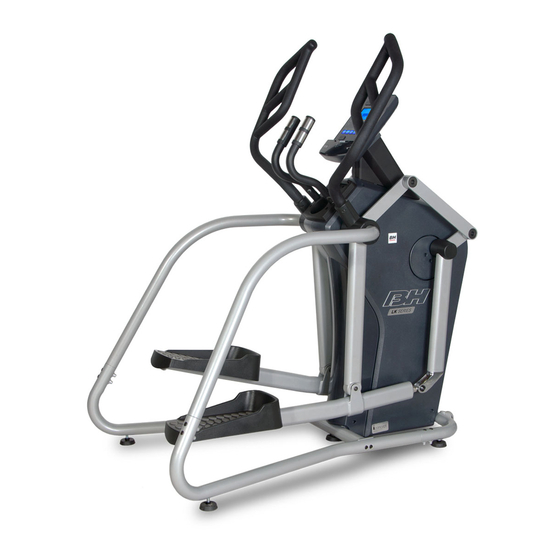
- Page 1 LK500Xi OWNER’S MANUAL Important: Read all instructions carefully before using this product. Retain this owner’s manual for future reference. BH North America | 20155 Ellipse, Foothill Ranch, California 92610 | p.949.206.0330 | f.949.206.0350 | www.BHFitnessUSA.com...
-
Page 2: Table Of Contents
TABLE OF CONTENTS Title Page Introduction Warnings and Labels Safety Information Exercise Instruction Training Guidelines Suggested Stretches Assembly Instructions Console Operations Maintenance and Cleaning Exploded View Drawing Parts List Warranty... -
Page 3: Introduction
CONGRATULATIONS Congratulations on your purchase of BH Fitness equipment. We hope you appreciate the style, quality, and value that exercisers around the world have come to expect from BH Fitness. If you have any questions, concerns or product issues please call our Customer Service Team at 1-866-325-2339 or email us at CustomerSupport@BHNorthAmerica.com. -
Page 4: Warnings And Labels
WARNINGS AND LABELS... -
Page 5: Safety Information
6. This machine must only be used for the purposes described in this manual. DO NOT use accessories that are not recommended by BH Fitness. Read manual prior to use and follow all warnings and instructions. 7. Do not place sharp objects near the machine. -
Page 6: Exercise Instruction
EXERCISE INSTRUCTION Use of the machine offers various benefits; it can improve fitness, muscle tone and when used in conjunction with a calorie controlled diet, it can help you lose weight. 1. Consult your doctor before starting any exercise program. It is advisable to undergo a complete physical examination. -
Page 7: Training Guidelines
TRAINING GUIDELINES Exercise is one of the most important factors in the overall health of an individual. Listed among its benefits are: • Increased capacity for physical work (strength endurance) • Increased cardiovascular (heart and arteries/veins) and respiratory efficiency • Decreased risk of coronary heart disease •... - Page 8 OXYGEN UPTAKE The effort that you can exert over a prolonged period of time is limited by your ability to deliver oxygen to the working muscles. Regular vigorous exercise produces a training effect that can increase your aerobic capacity by as much as 20 to 30%. An increased VO2 Max indicates an increased ability of the heart to pump blood, of the lungs to ventilate oxygen, and of the muscles to take up oxygen.
- Page 9 HEART RATE As you exercise, your heart beat increases. This is often used as a measure of the required intensity of an exercise. You need to exercise hard enough to condition your circulatory system, and increase your pulse rate, but not enough to strain your heart. Your initial level of fitness is important when developing an exercise program for you.
- Page 10 MUSCLE SORENESS For the first week or so, muscle soreness may be the only indication you have that you are on an exercise program. This, of course, does depend on your overall fitness level. A confirmation that you are on the correct program is a very slight soreness in most major muscle groups. This is quite normal and will disappear in a matter of days.
-
Page 11: Suggested Stretches
SUGGESTED STRETCHES Head Rolls Rotate your head to the right for one count while feeling the stretch up the left side of your neck. Next, rotate your head back for one count, stretching your chin to the ceiling. Rotate your head to the left for one count, and finally, drop your head to your chest for one count. - Page 12 SUGGESTED STRETCHES Inner Thigh Stretch Sit with the soles of your feet together with your knees pointing outward. Pull your feet as close into your groin as possible. Gently push your knees towards the floor. Hold for 15 counts. Toe Touches Slowly bend forward from your waist, letting your back and shoulders relax as you stretch toward your toes.
-
Page 13: Assembly Instructions
ASSEMBLY INSTRUCTIONS... - Page 16 STEP 1 Insert Left Connection Tube (P-1) into the Main Frame Set (A) left lower tube but do not insert all the way as shown below. Main Frame Set (A) Not inserted all the way. Left Connection Tube (P-1) STEP 2 Insert Left Handle Connection Tube (C) into Left Connection Tube (P-1) as shown below.
- Page 17 STEP 3 Insert Left Connection Tube (P-1) until the top part of Left Handle Connection Tube (C) aligns with mating spindle and insert as shown below. The top part of Left Handle Connection Tube (C) aligns with mating spindle. Fasten using attachment hardware V-10 (2) and V-11(2).
- Page 18 PEDAL & PEDAL POST DETAILS STEP 7 Fasten the Left Pedal Post Set (L) onto both attachment arm mechanisms on the Main Frame Set (A) with the assembly hardware as shown below. 1. First step is to attach the bearing end of Left Pedal Post Set (L) onto the attachment mechanism using attaching hardware V-12 (1) and V-13 (1).
- Page 19 STEP 8 Follow the same assembly procedures as above to assemble the right side.
- Page 20 STEP 9 Attach Left Swing Post Set (S) using the attachment hardware V-6 (3) and V-7 (3) as shown below. STEP 10 Follow the same assembly procedures as above to assemble the right side.
- Page 21 STEP 11 Attach Left Swing Arm Front Cover (H) and Left Swing Arm Rear Cover (I) using the attachment hardware V-8 (4). STEP 12 Follow the same assembly procedures as above to assemble the right side.
- Page 22 STEP 13 1. Attach the Computer Post (B-1) using attachment hardware V10 (2) as shown below. 2. Insert the Computer cable in the opening at the rear of the Computer Post (B-1) and pull through the top opening as shown in the diagram below. A-48...
- Page 23 STEP 14 Attach Left Handle Bar Set (F) onto the attachment tube as shown in the photo below. 1. Insert the Sensor Wire (F-3) into the installation tube and pull through the top of the Computer Post (B-1) as shown in the photo’s below. 2.
- Page 24 STEP 15 Follow the same assembly procedures as above to assemble the right side. STEP 16 Attach Sensor Wires (F-3 and G-3) and Computer Cable (A-48) to the Computer Set (U) and fasten the Computer using attachment hardware U-3 (4) as shown in the diagram below.
- Page 25 STEP 17 Attach Computer Post Cover (E) and plug in Power Adaptor (U-4) as shown in the figure below.
-
Page 26: Console Operations
CONSOLE OPERATIONS SPECIFICATIONS: ENTER To confirm all setting values RESET To reset all parameters to default value START/STOP To start or stop training To make upward setting change DOWN To make downward setting change RECOVERY In stop or start mode, pressing this button will start Heart Rate recovery status measurement. - Page 27 POWER MODE When the machine powers on, the display will light up with all numerals. After two seconds, it will enter the "user selecting" mode. If the user does not operate the machine, or the machine receives no signal after 4 minutes, the computer will enter an idol mode. GETTING STARTED - OPERATING PROCEDURE Start pedaling and the console will turn on.
- Page 28 3. Press ENTER to confirm the AGE setting, then enter the HEIGHT setting. The right side will display HEIGHT, use the UP/DOWN buttons to select the HEIGHT setting. 4. Press ENTER to confirm the WEIGHT setting, then enter WEIGHT setting. The right side will display WEIGHT, use the UP/DOWN buttons to select the WEIGHT value.
-
Page 29: Manual Mode
NAVIGATING THE PROGRAMS MANUAL MODE User may preset their own resistance level from 1 to 24 by pressing the UP/DOWN buttons. The default resistance level is 1. Press ENTER to confirm. Using the UP/DOWN buttons enter values for TIME, DISTANCE, CALORIES, PULSE, and then press START to begin your workout. - Page 30 PRESET PROGRAMS HRC PROGRAMS (55%, 75%, 90%, TAG) HRC 55% HRC 75% HRC 90% HRC Target Heart Rate TEST FUNCTIONS RECOVERY TEST Press the RECOVERY key to test HRC recovery speed. When in test mode, it will detect the HRC within 10 seconds. When finished, if there is no HRC displayed, the program will exit out of the HRC recovery mode.
-
Page 31: Fitness Test
Test result is shown below: VALUE CONDITION Best Very good Good Normal Worse FITNESS TEST Enter FITNESS program and start the test. Test time is 8 minutes. Test result is below: VALUE CONDITION Very Good Good Fair Poor Very Poor FUNCTION STATISTICS AND RANGES ITEM SCREEN SHOWN RANGE... - Page 32 WATT 0 - 999 0 - 250 rpm BRAKE RESISTANCE L1 - L24 LEVEL “WARNING! Heart rate monitoring systems may be inaccurate. Over exercising may result in serious injury or death. If you feel faint stop exercising immediately.
- Page 33 DOWNLOADING APPS AND PAIRING YOUR DEVICE WITH YOUR EQUIPMENT DOWNLOADING THE SOFTWARE Connect the Apple device with the App Store (iTunes) or your Android Device with Google Play, search for "Pafers", then read the APP introductions and Download the APPs with bicycle/elliptical machine functions to your device, for example Pedal Monitor or other applicable apps.
- Page 34 PAIRING THE BLUETOOTH DEVICE WITH AN ANDROID DEVICE 1. Place the Android Device on the area in front of the LCD screen. 2. Enter into settings and turn Bluetooth on. 3. Your Android Device will detect all Bluetooth devices within range (following on screen instructions), click on the appropriate bluetooth device name and confirm your connection.
-
Page 35: Maintenance And Cleaning
certified by the developer to meet Apple performance standards. Apple is not responsible for the operation of this device or its compliance with safety and regulatory standards. Please note that the use of this accessorywith iPod, iPhone, or iPad may affect wireless performance. -
Page 36: Exploded View Drawing
EXPLODED VIEW DRAWING... -
Page 38: Parts List
PARTS LIST To order replacement parts: provide your customer service representative with the product model number and the part number located on the Parts List below, along with the quantity you require. Description QTY. Description QTY. MAIN FRAME SET A-26-2 Bearing Main frame A-26-3... - Page 39 PARTS LIST To order replacement parts: provide your customer service representative with the product model number and the part number located on the Parts List below, along with the quantity you require. Description QTY. Description QTY. COMPUTER POST SET RIGHT CONNECTION TUBE SET Computer post Right connection tube Rubber ring...
-
Page 40: Warranty
For more detailed warranty information or to register your product warranty easily online, visit our website at: www.BHFitnessUSA.com FOR WARRANTY REPAIRS, PLEASE DO NOT TAKE YOUR MACHINE BACK TO THE RETAIL STORE. CONTACT BH FITNESS FIRST. BH North America Corporation 20155 Ellipse Foothill Ranch, CA 92610 Phone: 949.206.0330;...
Need help?
Do you have a question about the LK500Xi and is the answer not in the manual?
Questions and answers