Table of Contents
Advertisement
Advertisement
Table of Contents

Related Manuals for Moog MF-104


Summary of Contents for Moog MF-104
- Page 2 Its great sound and jaw- dropping effects come from state-of-the-art analog circuitry, designed and handcrafted by our team at Moog Music in Asheville, North Carolina. The MF-104M is rooted in the analog wizardry of Bob Moog’s Mooger- fooger designs.
-
Page 3: Getting Started
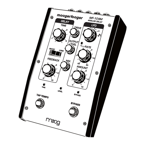
Save the box in case you ever need to ship your MF-104M back to Moog Music. 3. Don’t forget to register your Analog Delay. Why? Moog is constantly updating its products. The only way to know about an update is by registering. - Page 4 THE MF-104M FRONT PANEL LFO CONTROLS (RIGHT PANEL): LFO - Six-position rotary switch selects the LFO wave shape for delay The FRONT PANEL of the MF-104M Analog Delay contains the time modulation. Select from Sine, Triangle, Square, Ramp, Sawtooth, and performance controls and LED indicators.
-
Page 5: Setting Levels
NOTE: It only seems like magic. In actuality it’s some serious know how on the part 12:00 and the OUTPUT LEVEL to 9:00 as shown in Figure 1. of Moog’s product design team. 3. Press the BYPASS switch so the BYPASS LED turns green (Figure 2). - Page 6 Adjust the FEEDBACK as shown in Figure 7, and tap the the delayed signal back into the Delay Line. With the control set to about BYPASS switch to turn the effect OFF. Then press and hold 8, the echoes sustain indefinitely. With the FEEDBACK control set above 8, the BYPASS switch until the LED turns orange.
-
Page 7: Putting It All Together
• • FIGURE 13 effect courtesy of triangle wave modulation. Try plugging a Moog EP-2 expression pedal FIGURE 14 into the Rate CV jack and use it to speed up Take a few minutes to experiment with different WAVEFORM, RATE, and or slow down that stretching effect. - Page 8 2. VIBROLAY 4. SQUARE ROOT A spatial vintage style delay with triangle Prepare for octave action with this wave vibrato added to the trails. Try quick awesome square wave mod. Each note notes or chords combined with held notes. will rhythmically jump up and down a full Use the Rate and Amount knobs to add octave for percussive bliss.
- Page 9 ABOUT ANALOG DELAYS THE MF-104M FRONT PANEL A delay circuit produces a replica of an audio signal a short time after the This section provides more in-depth descriptions of the controls and original signal is received. If you listen to the original (direct) signal and the indicators on the MF-104M front panel.
- Page 10 OUTPUT LEVEL - Sets the strength of the Analog Delay output at the LFO RATE - Sets the frequency of modulation of the Delay Line by the MIX OUT and DELAY OUT jacks. This control is only active when the effect LFO.
- Page 11 THE MF-104M BACK PANEL This section provides greater detail of the connection points on the MF- TIME - 1⁄4” TRS jack that can be used with a Moog EP-2 expression pedal, 104M back panel. or a 0V to +5V control voltage on a standard TS cable. To change the DE- LAY TIME for a selected range from longest to shortest via control voltage or expression pedal, set the DELAY TIME control to 12:00 position.
-
Page 12: Circuit Configuration
CIRCUIT CONFIGURATION A MIDI CC message has both a CC number from 0-127 and a value from 0-127. The CC values that affect panel controls replace the physical setting The figure below is a simplified block diagram of the MF-104M Analog Delay. of the front panel controls. - Page 13 Used for updating or finding out the unit’s firmware version. For more 30-34 WH + 1/4 94-98 1/16 Dot information about this, refer to user notes with any firmware updates posted in the Analog Delay section of the Moog Music website. 35-40 99-104 1/8 T 41-46 1/2 Dot...
-
Page 14: Warranty And Service Info
Wrap your MF-104M carefully and pack it with the power adapter in its original carton. The warranty will not be honored if the product is not properly packed. Send it to Moog Music with transpor- tation and insurance charges paid. A reasonable cost for service, materials and return freight will be charged to replace materials defective through the fault of the user, or for which the one year warranty period has expired. - Page 15 Note: Specifications subject to change without notice. Moog®, and Moogerfooger® are registered trademarks of Moog Music Inc. ©2012 Moog Music Inc MOOG MUSIC INC. 160 Broadway St. Asheville, NC 28801 P: (828) 251-0090 E: info@moogmusic.com W: www.moogmusic.com...
Need help?
Do you have a question about the MF-104 and is the answer not in the manual?
Questions and answers