Advertisement
Quick Links
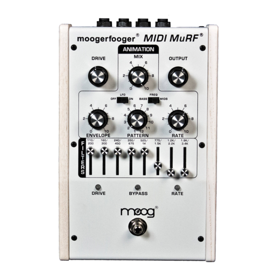
MIDI MuRF Analog Board 11-487
Theory of Operation,
Note: this circuit description refers to the REV A schematic dated 05/19/09.
SHEET 1
EFFECT_IN is the audio signal taken after the bypass switch on page 6. The input network
C5/58-R5-R6-C4 provides DC isolation, radio frequency filtering, and protection of input
amplifier U3A. The output of U3A is the signal AUDIO, which is the amplified audio input
signal.
Negative feedback around U3A goes through U2-A. U2 is a VCA whose gain is controlled by
the current through Q1, which is the sum of the current through R11 and D17/R121. U3B is a
sample-and-hold buffer with level and offset adjustment. The output of this amp determines the
voltage across Rl1.
U14B and associated components are used to buffer, isolate, and attenuate the audio signal from
the audio bus. It is then fed to the MPU to be used as a 0-2.4V DC reference signal for the
compandor circuit. D3 conducts when the peak voltage at U13A is higher than the
COMPANDOR voltage. The COMPANDOR voltage is held by C30 and a capacitor on the
digital board, where it is scanned by the microprocessor. The purpose of the COMPANDOR
voltage is to determine what the highest peak voltage is at the input to the filters. This enables
the microprocessor to determine the status of the overload LED, and perhaps cut down the gain
of the input amplifier to reduce overload distortion.
UI2B is a sample-and-hold buffer with level shifting and gain. Its output is the Direct VCA
CONTROL signal. It controls the overall gain of the direct (non filtered audio) VCA (Sheet 6).
U14A is a sample-and-hold buffer-level shifter / amplifier. Its output is the Filter VCA control
signal. It controls the overall gain of all filter VCAs (Sheets 2 though 5). Note that the Filter
VCA signal is a diode drop across Q16. The current through Q16 is determined by the voltage
at the output of Ul4A and by R50. This is a current mirror configuration. There is a transistor in
each of the filter VCA circuits that matches the properties of Q16.
U10 is a de-multiplexer that routes one of the microprocessor D-A outputs to the inputs of U3B,
U12B, UI4A, and U14B. The signals Mux_A and Mux_B signals select the output routing,
while the signal Mux_EN inhibits U10 when it is high.
Advertisement

Related Manuals for Moog Moogerfooger MF-105M MIDI MuRF


Summary of Contents for Moog Moogerfooger MF-105M MIDI MuRF
- Page 1 MIDI MuRF Analog Board 11-487 Theory of Operation, Note: this circuit description refers to the REV A schematic dated 05/19/09. SHEET 1 EFFECT_IN is the audio signal taken after the bypass switch on page 6. The input network C5/58-R5-R6-C4 provides DC isolation, radio frequency filtering, and protection of input amplifier U3A.
- Page 2 SHEET 2 U5B is a comparator and level shifter that takes the signal from the MPU and converts it from 0-3.3V to +/-5V with some hysteresis. This signal is used by the Mux switches to select the regular or base voicing of the filters. U5A works in the same way as U5 to convert a duty cycle modulated PWM signal from the MPU to be used as the shift input to the SHIFT Mux.
- Page 3 The output of the filter is applied through C28 and R41 to the bases of Q10 and Q6. The transconductance of this transistor pair is proportional to the current through them, which is the same as the current through Q9. The network of U11B, R40, and Q5 is a voltage-to-current converter.
- Page 4 SHEET 7 The power inverter and regulators are shown in the upper right corner. D8 provides polarity protection. It is a low Vf Schottky diode so that the linear regulators do not reach drop out voltage. D1 conducts if an over voltage situation occurs (power spikes or the wrong input voltage).
- Page 5 MIDI MIDI may be tested in several ways. The easiest way is to use the MIDI testing tab of the Moog utility “MIDI_MuRF.exe” The first tab has some MIDI controls on it. Other ways include using a simple sequencer that may be downloaded from http://www.reaper.fm/download.php...
- Page 6 MIDI MuRF DIGITAL BOARD CHECKOUT PROCEDURE Modified July 2009 from the original May 28, 2004 Version Initial Firmware load and check out 1. Install B.U.T. • Place the Digital Board Under Test onto test fixture and clamp down. a) Verify that there is an insolated washer on each screw terminal before placing B.U.T on PCB.
- Page 7 • All three green LEDs are lit up. (Note if this does not happen due to reworked board power up with two B.U.T. switches to right while pressing bypass switch to boot in bootloader mode). • Verify total 9.5V current draw is under 200mA (around 165mA) •...
- Page 8 5. Run the Moog “MM_Tester_v1.0_122.exe” application to finish programming. a. If there are not 3 green LEDS on the B.U.T then boot in hidden mode by sliding LFO and FREQ switches to the right and powering up with the bypass button pressed.
- Page 9 UI and I/O Testing. 6. ON/BYPASS FUNCTION (“Stomp Switch”): Press the Bypass STOMP SWITCH on the tester panel. a. The middle LED on the B.U.T. should alternate between green and red. (Tests LED and Switch input to MPU) b. The BYPASS / ON LED on the fixture panel should light up yellow when the LED on the B.U.T.
- Page 10 turn the ENVELOPE pot slowly through its range. c. The individual envelope LEDs should indicate that the envelope shape is changing. The envelopes should be very short when the ENVELOPE pot is at either extreme, or long when the pot is in the middle. If you observe the conditions, then the ENVELOPE pot and the ENVELOPE EXTERNAL input are working.
- Page 11 a. The LFO/PWM RATE LED should pulsate at a rate of a few times a second. Now slowly vary turn the LFO/SWEEP EXTERNAL control clockwise through its range. b. The pulsation of the LFO/PWM LED should vary from very slow to very fast. Flip the LFO switch back to OFF (left) c.
- Page 12 MIDI is verified by loading the application firmware. However if the application is already loaded it may be necessary to use another MIDI verification test. If so run MIDI_MuRF.exe and connect a midi channel. Using the control tabs adjust a slider or button and verify that the B.U.T functions as if that knob was changed on the B.U.T.
-
Page 13: Appendix A - Midi Cc Messages
Appendix A – MIDI CC Messages The following MIDI Control Change messages are recognized: CC1 – Envelope (Note – one of the most expressive ways to “play” the MuRF is to modulate the Envelope time control manually – a mod wheel would be the perfect type of controller for this – especially if you are using one of the Note On modes) CC Value 000-003 = Env value 1, CC Value 004- 007 = Env value 2, etc…... - Page 14 Quick firmware installation guide for MIDI MuRF: 1.) load "bootloader" firmware (MM_Booter_v1.0_122.hex) via Silabs USB Debug Adapter and Silabs Flash Programming Utility software for Windows-PC. Flash Programming Utility software can be downloaded (as of 11- 2009) from this link: https://www.silabs.com/Support%20Documents/Software/UtilDLL.zip 2.) Cycle power to unit;...
Need help?
Do you have a question about the Moogerfooger MF-105M MIDI MuRF and is the answer not in the manual?
Questions and answers