
Subscribe to Our Youtube Channel
Related Manuals for HP 5304A

Summary of Contents for HP 5304A
- Page 1 O P E R A T I N G A N D S E R V I C E M A N U A L TIMER/COUNTER 5304A w . 0 « ( i O t l HEWLETT M PACKARD...
- Page 2 CERTIFICATION The Hewlett-Packard Company certifies that this instrument thoroughly tested and inspected and found to meet its published specifications when it was shipped from the factory. The Hewlett- Packard Company further certifies that its calibration measure- ments are traceable to the U.S. National Bureau of Standards the extent allowed by the Bureau's calibration facility.
- Page 3 III' M < > 1 >EL5;MMA TIMER colINTER Reeord of Revisions (Manual Change I'ages) REVISION DATE INSERTED DATE NUMBER INSERTED ISSUED...
- Page 4 HI' MODEL : " >; { ( M A TIM E R CO IJNTK K Record of Revisions (Manual Change Pages) REVISION DATE DATE INSERTED NUMBER ISSUED INSERTED...
- Page 5 "Manual Changes Pages" applies directly to HP Model 5.'U)4A Timer C o u n t e r s having prefix numbers above 1212A00467. OLDER INSTRUMENTS Changes re(|uired to back-date this Section for older instru- ments arc in Section IX I), Subsection VII.
- Page 6 Model 5304 A Table of Contents T A B L E O F C O N T E N T S Section i'age IX I) 5304A Timer/Counter Subsection GENERAL INFORMATION 91)1-1 91)-1-1. Introduction 9D-1-1 91)-1-2. Description 9D-1-1 91)-1-4. Purpose and Use of Section IX I) 91)-1-1 91)1-6.
- Page 7 9D-5-I5 9D-8-1. Al Time Interval Board Assembly, A2 Attenuator Board Assembly 9D-8-5 LIST OF T A B L E S 1 able Page 9D-1-1. 5304A Timer/Counter Specifications 9D-1-2 9D-5-1. In-Cabinet Performance Checks 9D-5-16 9D-6-1. Replaceable Parts 9D-6-2 9D-6-2. Manufacturers Code List 9D-6-5 9D-8-1.
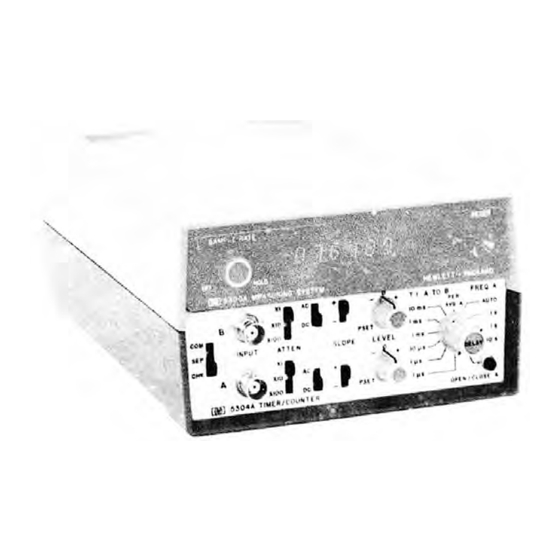
- Page 8 Model 5304A General Information Figure 91)-1-1. 5304A Timer/Counter :»::i :t w FREQ A AUTO XIOO ® PSET^»*» ATTEN xioo a i oc ^ OPEN/CLOSE A 5304A TIMER/COUNTER 9D-1-0...
- Page 9 The first four 9D-1-3. The Hewlett-Packard Model 5304A Timer digits are the serial prefix and the last five digits Counter, when plugged onto an HP Model 5300A refer to the specific instrument. If the serial prefix Measuring System, is capable of:...
- Page 10 May be used decimal point. to intensity modulate an HP oscilloscope. O P E N / C L O S E (Totalizing) T I M E I N T E R V A L R a n g e : 10 MHz maximum.
- Page 11 The original container is a corrugated card- Tables 1-2 and 1-4 of 5300A portion of the manual board box with 200 lbs. burst test (HP No. 9211-1620). list the HP 5310A Battery Pack as an available The instrument is secured and protected, while in accessory.
- Page 12 O P E R A T I O N...
- Page 13 O P E R A T I O N 9 D - 3 - 1 . OPERATING INFORMATION 9D-3-3. There are four basic signal conditioning controls used in Channel A or Channel B (the effect 9D-3-2. The 5300A/5304A Timer/Counter measures these controls shown Figure 9D-3-1).
- Page 14 AVO/A XlOO AYTEN LEVE .1 ms 0 0 ^ OPEN.XCLOSE A K g ] 5304A TII/ER/COUNTER INPUT A and B. Input signal frequencies COM-SEP-CHK. Three position switch to be measured are connected to INPUT enables selection of input signal from...
- Page 15 Model 5304A Operation Figure 9D-3-2. Front-Panel Controls and Connectors (Continued) AC-DC. Two-position switch allows c. FREQ Enables frequency selection of ac-coupling or direct-coupling measurements from 0 to 10 MHz to input amplifiers. when dc coupled and 100 Hz to 10 MHz when ac coupled.
- Page 16 Model 5304A Operation Figure 9D-3-3 Rear-Panel Connectors GATE OUT DELAY OUT GATE OUT: A TTL-LOW level signal while the 5300A main gate is open. DELAY OUT: A TTL-LOW level signal during the delay time selected by front- panel DELAY control (in T.I. A to B...
- Page 17 Connect ac power to 5300A ac receptacle. Turn ac power "on" with 5300A SAMPLE KATE control. Adjust SAMPLE KATE for desired display time. Set 5304A COM SEP-CHK switch to CHK. Set 5304A "Function" switch to FREQ A, AUTO. Display should he 10.0000 MHz, + 1 count.
- Page 18 Model 5304A Operation Figure 9D-3-5. Making Frequency A Measurements I ( R E A R ) FREQ A T . I . A TO B 10 ms v AVG ' AUTO • t ms — ^ P S E T ^...
- Page 19 Model 5304A Operation Figure 9D-3-6. Making Period Average Measurements I (REAR) FREQ A NPUT xioo m D C • 5 3 / 4 A T I M E R / C O U N / Connect tic power to 5300A ac receptacle.
- Page 20 Model 5304 \ Operation Figure 9D-3-7. Making Time Interval Measurements l(REAR) AUTO Connect ac power to 5300A ac receptacle. Adjust ATTEN switches until a stable dis- play is obtained. Turn ac power "on" with 5300A SAMPLE Time Interval Holdoff (DELAY). RATE control.
- Page 21 Model 5304A Operation Figure 9D-3-7. Making Time Interval Measurements (Continued) If the input signals are pulse trains, HP 182!A: Set TRIGGER to EXT. it is possible to select a pulse out of SLOPE to -. the train by increasing the DP]LAY Coupling to ACF.
- Page 22 Model 5304A Operation Figure 9D-3-8. Totalizing l(REAR) SAMPLE RATE GSD 5300A MEASURING SYSTEM HEWLETT • PACKARD' "1 - * T.I. A TO 8 FREQ A 10 m s AVG A , AUTO \ ' V P S E T '...
- Page 24 Q2 and Q4 are connected to the operation of the 5300A 10 MHz crystal oscillator differential amplifier Q6 and Q8 respectively and and counting logic and the 5304A gating logic is provides level shifting and gain of approximately verified. When A2S1 is in CHK mode, ground is .3 for Channel A signals.
- Page 25 U12C as the F2 signal to control the time base, The main gate closes because no more counts can which clocks the opening and closing of the main be stored in the 5304A exponent counter U8A and U8B. gate. The exponent counter counts the number of decade-...
- Page 26 Model 5304A Theory of Operation 9D-4-29. The 5300A main gate cannot be re-opened signal from the 5300A A1J 1(18) is gated through until U15B is cleared by the RESET signal at Q18, U17F, U9B, and U16B to be counted (except in the .1 fjsec position, where the 10 MHz clock is...
- Page 27 M A I N T E N A N C E...
- Page 28 5300A and 5304A castings should be separated by cbout '/g-inch. a. Solder Gobbler. Solder is removed from d. Lift the 5300A gently away from the 5304A. board by a soldering iron with a hollow tip con nected to a vacuum source. The IC is removed...
- Page 29 Model 5304A Maintenance Figure 9D-5-1. Separation Procedure...
- Page 30 Model 5304 A Maintenance performance checks indicate a malfunction or if a. Connect an HP 651B Oscillator, set to 10 instrument operation is suspect, perform the Self- MHz, 50 mV rms/5012, through a 50 OHM BNC Feed- Check procedures in Table 9D-5-1. For further tests, thru Termination, to Channel A input.
- Page 31 H (dim). Flash rate decreases as 5300 SAMPLE RATE control is truned cw. INPUT: H (dim). Flash rate decreases as 5300 HP 651B set to 10 MHz, 100 mV rms/50S2. SAMPLE RATE control turned I^evel goes Low when 5300A RESET is pressed.
- Page 32 .01 V/cm .01 V/cm .01 V/cm .2 V/cm .1 \i sec/cm .l|J.sec/cm . lfisec/cm . 1 fJ-sec/cm dc coupled .2 V/cm .2 V/cm .1 V/cm ® .1 V/cm .1 (isec/cm . 1 (isec/cm .1 fj-sec/cm .1 fisec/cm dc coupled dc coupled 1 V/cm ©...
- Page 33 Ai TIME INTERVAL BOARD ASSEMBLY OSKX-SOOQI: A2 ATTENUATOR BOARD ASSEMBLY 60CQ?I Q t v a * j • 0 0 B 0 • PA) AlPI 1" " CM) _5i5 < 0 0...
- Page 34 &TQR BOARD ASSfMBlY ">M04 «oc fuse) —f>" i»"53TW • > 9 <5»T*t 410 enw > TIME BASE 0 0 1 I—[->»' 5 OiGlT S f L E C l ' — !->*> S' D>G'T A0CWES5 O i A K t C L B SLOPE a E C T O H ;•...
- Page 35 RATE is turned cw. Goes Low when RESET is pressed. Oscilloscope: TP2 H (dim). Flash rate decreases when 5300 SAMPLE HP 180A, 1801A Vert Amp, 1821A T.B. through RATE is turned cw. Goes Ix>w when RESET is a 10:1 probe. pressed.
- Page 36 ® .01 V/cm .01 V/cm .05 V/cm .2 V/cm 1 msec/cm 1 msec /cm .5 msec/cm 50 jisec/cm dc coupled dc coupled .2 V/cm .2 V/cm © .2 V/cm .2 V/cm .5 msec/cm .5 msec/cm . 1 fjLsec cm .1 |.isec/cm dc coupled dc coupled dc coupled...
- Page 37 Ai TIME INTERVAL BOARD ASSEMBLY iosw< toooM A2 ATTENUATOR BOARD ASSEMBLY u m o * 6000?) -4 D Q tm • D ® * - 0 f Ll vT. «"1 rtevtL 8 1 © • 0 0 0 0 0 s i s P/O AlPI a>s~, ;...
- Page 38 A> TIME I N T E R V A L BOARD A S S E M B L E • - c o o A S S E M B L Y (09J04 6000?! ; _ O I T .015 0 1 6 [ LtVU"...
- Page 39 Function to .1 fosec. From the set-up outlined in Figure 9D-5-4A, dis- C O M / S E P / C H K to SEP. connect the Channel A input to the HP 180A Oscil- loscope. Connect a 10:1 divider probe and check Oscilloscope: for the waveforms listed.
- Page 40 Model 5304A Maintenance Part of Figure 9D-5-4. Time Interval Troubleshooting Diagram .1 V/cm .05 V/cm .05 V/cm .1 [isec/cm . 1 |j.8ec/cm . 1 fisec/cm - Slope dc coupled - Slope .2 V/cm .2 V/cm .1 V/cm .05 V/cm .1 jisec/em .
- Page 41 Model 5304A Maintenance Part of Figure 9D-5-4. Time Interval Troubleshooting Diagram © .2 V/cm .2 V/cm .2 V/cm .1 jj.8ec/cm . 1 (isec/cm .1 fisec. <-m dc coupled dc coupled dc coupled .2 V/cm .2 V / c n .2 V/cm .1 msec/cm...
- Page 42 © H © A .5 V/cm .5 V/cm .5 V/cm 50 |j.sec/cm 50 jisec/cm 50 fisec/cm dc coupled dc coupled dc coupled (DELAY just out < > f (I)BLAY just out of (DELAY IN DETENT) DETENT. 5300A Dis- DETENT. .5300A Dis- play should be ap- play time should be proximately...
- Page 43 A! TIME INTERVAL BOARD ASSEMBLY tos* A2 ATTENUATOR BOARD ASSEMBLY <oao* tooo?) Q 0 B Q 0 0 E * 3 . 8 i s m fog P/0 AlPl < ? 6 " E?(S) £212) 51? en?) a...
- Page 44 TIME I N T E R V A L HOAHD A S S t M b L Y (0S304-60000 • ) tOC Ol/TPOT ^ < * OPT*I • iO K55E 011 400Ht5s O 1 i ) J6 J' c u t s ' * , B 1—rr_l^s SlDPt St- ECTlON ] 1 ^*1 * I...
- Page 45 TP2 L. Goes High when RESET is pressed. Re- Oscilloscope: mains High if this switch is held depressed. HP 180A, HP 1801A Vert Amp, HP 1821A T.B. TP3 L through a 10:1 probe. L. Goes High when OPEN/CLOSE is pressed...
- Page 46 .01 V/cm 20 msec/cm ® .02 V/cm .05 V/cm ® .2 V/cm 20 msec/cm 50 msec/cm 50 msec dc coupled dc coupled © .2 V/cm .2 V/cm .2 V/cm 50 msec/cm 50 msec/cm 50 msec/cm dc coupled dc coupled dc coupled...
- Page 47 AI TIME INTERVAL BOARD ASSEMBLY it A? ATTENUATOR BOARD ASSEMBLE « m 0 4 6Qoo?i ED > • • I LtVtl * | I ItVCL B 1 • 0 • • 0 Q E«D,5 ® " » P/0 AlPl -r-<?6 + I7V OOljiF €...
- Page 48 TIME I N T E R V A L B O A R D A S S E M B L Y IOSSO*-6000.: , D E L A * (5PTSi ^ 10 5.T55T TIME BASE OUT DIGIT SELECT OANNEL e SLOPE SELECTION 9 £V I LEVEL * |...
- Page 49 5300A Display should 10.0000 ±1 count. Oscilloscope: HP 180A, HP 1801A Vert Amp, HP 1821A T.B. through a 10:1 probe Settings: AC coupled (except as noted). NORM sweep mode. + Slope (except as noted). AC (except as noted). Channel A.
- Page 50 .2 V/cm . 1 fj.sec/cm dc coupled • .2 V/cm .2 V/cm .2 V/cm • * M- 1 fisec/cm . 1 fjLsec/cm decoupled decoupled dc coupled...
- Page 51 A2 ATTENUATOR BOARD ASSEMBLY COSJO*-coooz) Al TIME INTERVAL BOARD ASSEMBLE y0'5 fl-n 013^ • 0 0 0 0 B Isp.5 v ** ; [ 5 ^ D El IS) "i>IS iP O h Mv - 'wouLArmis -2ULL - ten m o *" *•"...
- Page 52 Al TIME INTERVAL BOARD ASSEMBLY <OSJO4 SJ U3* / ' LOG OUTPfT &rh • • C M M N E L M DIGIT SELECT E O K SELECTION I t t v u * 1 I LEVEL » I DIGIT AOORfSS •...
- Page 53 1. CHK mode and Time Interval Holdoff. RANGE: dc coupled: 0 to 10 MHz. Set 5300A OSC switch to INT. ac coupled: 100 Hz to 10 MHz. Mate 5300A to 5304A and ensure casting latches at rear of 5300A are Sensitivity as in Table 9D-1-1. latched.
- Page 54 REP RATE for 10 Hz. Monitor the oscilloscope and set 651B con- Set 5304A Channel A controls as follows: trols for 10 Hz, 100 mV rms output. ATT EN switch to XI Display should be approximately * 00.0000 AC-DC to DC MS, C <* = OVERFLOW) (100 msec).
- Page 55 Set Oscilloscope DISPLAY control to 5300A display and oscilloscope display A + B to monitor No.2 pulse position. should indicate the same time intervals. Set 5304A control as follows: 1. ATTEN (both channels) to XI. 2. AC-DC (both channels) to DC. NOTE 3.
- Page 56 Channel A ATTEN to Xl; 5300A display should Connect 651B 50-0hm output, set to accumulate. 10 Hz at 100 mV rms, to 5304A Chan- nel A INPUT connector. To stop 5300A from accumulating, press OPEN/CLOSE A. To continue accumu-...
- Page 57 Model 5304A Maintenance PERFORMANCE CHECK TEST CARD Hewlett-Packard Model 5300A/5304A Test Performed by TIMER/COUNTER Serial No Date Description Check 1. CHECK Mode and Time Interval Holdoff. • Display is 10 MHz ±1 Count. Hold off as in Table 9D-5-1, item 1, step i.
- Page 58 P A R T S L I S T...
- Page 59 This subsection contains information for Packard part number. To obtain a part that is not ordering replacement parts. Table 9D-6-1 lists parts listed, include: used in the HP 5304A. a. Instrument model number. 9D-6-3. ORDERING INFORMATION b. Instrument s ?rial number.
- Page 60 Model 5304 A Replaceable Parts Table 9D-6-1. Replace Parts Reference HP Part Number Description Mfr Part Number Code Designation BOAHD ASSY TIMR INTERVAL (Not available for field 05304 60001 28480 05304 60001 replacement or vile) (Includes A2. 05304 6000?) 01 w-ooso...
- Page 61 Model 5304A Replaceable Parts Table 9D-6-1. Replaceable Parts (Continued) Reference Mfr Part Number HP Part Number Description Code Designation 2 8 4 8 0 2 1 0 0 - 1 ' 6 8 PSVAS W W 20 OHM 5 *...
- Page 62 Model 5.304A Replaceable Parts Table 9D-6-1. Replaceable Parts (Continued) Reference HP Part Number Description Mfr Part Number Designation Code A 2 J 1 1 2 5 0 - 1 1 6 3 CONNf CTDP : R F 8NT. INPUT 2B4H0...
- Page 64 Table 9D-7-1, 7-2, 7-3, and Figure 9D-7-1. To back date the manual, do the following: Replace the 5304A Title Page with the replacement page containing Tables 9D-7-1 and 7-2. Replace page 9D-6-3 and 9D-6-4 with replacement page containing Table 9D-7-3 and 7-4.
- Page 65 Model 5304A Manual Changes and Options Table 9D-7-1. 5304A Section IX I) Timer/ Counter Title Page SECTION IX D TIMER/COUNTER 5304A S E R I A L P R E F I X : 1116A This section applies directly to HP Model 5304A, Timer/ Counters having serial prefix number 1116A, and must be inserted into the 5300A Measuring System Manual.
- Page 66 Model r»:wMA Manual Changes and Options Table 9D-7-2. Table of Contents TABLE OF C O N T E N T S Section Page IX D 5304A Timer/Counter Subsection GENERAL INFORMATION 91) 11 91)1-1. Introduction 91)1-1 9D-1-2. Description 91)1-1 91)1-4. Purpose and Use of Section IX I) 91)1-1 91)1-6.
- Page 67 Model 5304A Manual Changes and Options Table 9]>-7-8. Replaceable Parts Reference Mfr Part Number Description HP Part Number Code Designation 2 8 * 8 0 7 1 0 0 - 1 7 6 8 : VAF MM 70 OHM 5 *...
- Page 68 Model 5304A Manual Changes and Options Table 90-7-4. Replaceable Parts Reference HP Part Number Description Mfr Part Number Designation Code A2J 1 1 2 5 0 - 1 1 6 3 CONNECTOR sRF BNC INPUT 2 8 4 8 0...
- Page 69 » E2( I) — R48 E2(6) — R55 E2(2) — R54 E2(7)— R5 I El(6) — R50 E2(3)—R52 E2(8)—R53 EU7)— R56 E2(4)—R59 El(8) — R58 E2(5) — R57 » A2 Bottom...
- Page 70 NOTES REFERENCE DESIGNATIONS WITHIN THIS ASSEMBLY AWE ABBREVIATED ASSEMBLY NUMBER TO ABBREVIATION EOR COMPLETE DESCRIPTION UNLESS OTHERWISE INDICATED RESISTANCE IN OHMS. CAPACITANCE IN PICOFARADS A2 ATTENUATOR BOARD ASSEMBLY ioiJO« sooo?. REFERENCE DESIGNATIONS PREFIX CI 15 CRI-IB E l . ? 01-19 R4 5 Rl - 70...
- Page 71 TiME N T E P V A L BOARD ASbEMBLY <0530« - 6000 • 0 1 6 0 0 0 0 0 0 P/Q A I P l 0 Oh - > 3 3 fir Figure 9D-7-1. Al Time Interval Board Assembly A2 Attenuator Board Assembly o n 7 7...
- Page 72 S C H E M A T I C D I A G R A M S...
- Page 73 SECTION IX D 5 3 0 4 A T I M E R / C O U N T E R S U B S E C T I O N VIII CIRCUIT DIAGRAMS 9D-8-1. GENERAL 9D-8-2. Subsection VIII contains: a.
- Page 74 Model 5304A Circuit Diagrams Table 9D-8-1. Instrument Interconnection List PIN NO. SIGNAL NAME DESCRIPTION +5 V -5 V Input DC from 5300A -17 V GROUND This is the signal to be accumulated in the counter after gating by the control circuit.
- Page 75 Model 5304A Circuit Diagrams Table 9D-8-1. Instrument Interconnection List SIGNAL NAME DESCRIPTION PIN NO. NO CONNECTION p-36 p-36 DIGIT ADDRESS X ^ 3 7 ^ 3 7 DIGIT SELECT X Digit address code X, Y, Z from the display scanner indicates a digit being displayed.
- Page 76 Model 5304A Circuit Diagram Part of Figure 91) 8-1. 5304A Block Diagram PER AVERAGE FREO AUTO E X P O N E N . C O N T R O L USA/B EXPONENT COUNTER U7A/B EXPONENT TRANS STORAGE A INPUT T.I.
- Page 77 EfflEI •^yywA. El (3) — R60 E2( I) — R48 E2(6)—R55 EI (5) — R49 E2 (2) — R54 E2(7)-R5I EU6) — R50 E2(3) — R52 E2(8) — R 5 3 El (7) — R56 E2(4)—R59 El (8) — R58 E2(5) —...
- Page 78 NOTES REFERENCE DESIGNATIONS WITHIN THIS ASSEMBLY ARE ABBREVIATED ASSEMBt* NUMBER TO ABBREVIATION FOR COMPUTE DESCRIPTION UNLESS OTHERWISE INDICATED RESISTANCE IN OHMS. CAPACITANCE IN PICOFARADS A T T E N U A T O R BOARD ASSEMBLY 3»JO« - s o o o i ) R l f FRENCt DESIGNATIONS CI - i s CRI-18...
- Page 79 iSEMBLY 35S04-6000?> Ai TiME INTERVAL BOARD ASSEMBLY iOSJ04-60(X>o f >0 C55T | I t V t L | L t V t L » | I—&»' « • E E • 1 3 0 LA y, OKJ' T 4 i u m S.CH* SCLCCTlO* &...
- Page 80 M A N U A L C H A N C E S...
- Page 81 1212A *** Check following table for your instrument's serial prefix or * DATE PRINTED: AUG 1973 series number and make listed * HP PART NO: 05304-90006 change(s) to manual. * MICROFICHE NO: 05304-90009 ftftftftftftftftft********** 0 INDICATES NEW OR REVISED ITEM >...
- Page 82 Page 9D-6-4, Table 9D-6-1, Replaceable Parts: >Add A2S1; 3101-1598; SWITCH-SLIDE DP3T 0.5A 125V AC/DC; 28480; 3101-1598. / / P a g e 9D-6-4, Table 9D-6-1, Miscellaneous Replaceable Parts: >Change CASE part number from 05300-20010 to 05300-20006 in HP and Mfr Part Number columns.
- Page 83 Page 9D-6-3, Table 9D-6-1, A2 (05304-60003) Replaceable Parts: >Add (SERIES 1940) to A2 Description. >Change A2S1, S2 and S3 from 3101-1598 to 3101-2383 in HP and Mfr Part Number columns. >Change A2S4 thru S7 from 3101-1596 to 3101-2334 in HP and Mfr Part Number columns.
- Page 84 MANUAL CHANGES MODEL 5304A (05304-90006) Page 3 CHANGE 5 (Serial Prefix No. 2024A) Page 9D-6-3 A2 (05304-60003), Replaceable Parts: >Change A2 (05304-60003) Series Number to 2024A. Page 9D-6-4 A2 (05304-60003)* Replaceable Parts: >Change A2S1, S2 and S3 from 3101-2383 to 3101-1313;SWITCH-SLIDE DPDT 0.5A 125V 28480;...
- Page 85 •* < 1 M A N U A L C H A N G E S MANUAL IDENTIFICATION ~ Model Number: 5 3 0 4 A Date Printed: A u g u s t 1 9 7 3 Part Number: 0 5 3 0 4 - 9 0 0 0 6 This supplement contains important information for correcting manual errors and for adapting the manual to instruments containing improvements made after the printing of the manual.
- Page 86 05304-90006 Model No. 5304A ERRATA (Cont'd): Page 9D-5-18, Table 9D-5-1, I n Cabinet Performance Checks: Change Step e.4. to "COM'SEP-CHK to SEP". Change Step e.5. to "LEVEL (both channels) to position giving most stable display". Page 9D-6-2/3, Table 9D-6-1: Change A1R19/20 to 2100-1985.
- Page 87 Add the following under NOTES: "A1Q1/A1Q3 and A1Q2/A1Q4 ARE DUAL JFET N-CHAN UNITS WITH CENTER LEAD TO CASE CUT OFF". Change Ql-4 in TABLE OF ACTIVE COMPONENTS to Ql/q3, Q2/Q4 and HP PART NUMBER to 1855-0213. Page 9D-8-5: I n table of active components: Change U15 to 1820-1112.
Need help?
Do you have a question about the 5304A and is the answer not in the manual?
Questions and answers