Zanussi Hobs Operating And Installation Manual
Zanussi hobs
Hide thumbs
Also See for Hobs:
- Instruction booklet (12 pages) ,
- Operating and installation manual (8 pages) ,
- Instruction booklet (16 pages)
Advertisement
Advertisement
Table of Contents

Related Manuals for Zanussi Hobs


Summary of Contents for Zanussi Hobs
- Page 1 ZANUSSI Hobs OPERATING AND INSTALLATION MANUAL...
-
Page 2: Technical Data
L.P.G. Gas Appliance caliber Natural Gas 1,0 kPa 25,84 MJ/h Conversion to use with L.P.G. 2,75 kPa 25,56 MJ/h Gas entry connection G1/2 Voltage tension 240 V 50 Hz MANUFACTURER: ELECTROLUX ZANUSSI ELETTRODOMESTICI S.p.A. Viale Bologna, 298 47100 FORLÌ (Italy) - Page 3 WARNINGS - GAS HOBS It is most important that this instruction brochure should be kept together with the appliance for future consultation. If the appliance is sold or transferred to another person, ascertain that the brochure is also given, in order that the new user can be aware of the correct use of the machine and the relative warnings.
-
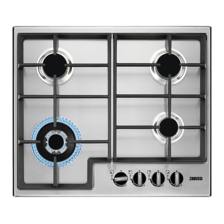
Page 4: Instructions For The User
INSTRUCTIONS FOR THE USER 1. Hob Top 2. Rapid Burner 3. Semirapid Burners 4. Auxiliary Burner 5. Control Panel 6. Control knob for back left burner 7. Control knob for front left burner 8. Control knob for front right burner 9. - Page 5 INSTRUCTIONS FOR USER INSTALLATION All operations relating to installation, regulation and adaption to the type of gas supplied, must be carried out by qualified personnel, according to the regulations in force. Specific instructions are contained in the notices reserved for the installer. IMPORTANT If after a few attempts the burner does not ignite, check that the baffle and its cap are correctly...
-
Page 6: Maintenance And Cleaning
It is never advisable to use wire pads, steel wool or acids for cleaning. For hobs having automatic ignition periodically carry out an accurate cleaning of the ignitor (ceramic or electrode) to avoid ignition difficulties, furthermore check that the baffle holes are not obstructed. - Page 7 CONNECTION CONNECTION TO THE GAS SUPPLY Carry out the connection to the gas plant only by Gas connection must be carried out in conformity means of a rigid metallic tube conforming to the with the regulations in force. The appliance regulations in force.
-
Page 8: Electrical Connection
ELECTRICAL RIGID METALLIC TUBE OR FLEXIBLE STAINLESS STEEL TUBE CONNECTION The appliance is predisposed to function with a 230V monophase voltage tension. Connection must be carried out in conformity with the CLAMPS regulations and dispositions of the laws in force. Before connecting ensure that: - The limiter valve and the electrical mains can support the voltage of the appliance (see... -
Page 9: Adaptation To Different Types Of Gas
ADAPTATION TO DIFFERENT TYPES OF GAS SUBSTITUTION OF THE NOZZLES Remove the grills: Remove the caps and baffles from the burners: With a tubular spanner no. 7 unscrew and remove (fig. 5) the nozzles substituting them with those corresponding to the type of gas used (see tab): Remount the parts carrying out the operations described in reverse. - Page 10 a) minimum regulation screw FO 1045 b) normal tap c) valvular tap Fig. 8 Fig. 9 TYPE TYPE NOZZLE NOMINAL REDUCED NOMINAL OF GAS OF BURNER MARKS THERMAL THERMAL PRESSURE 1/100 mm CAPACITY CAPACITY MJ/h MJ/h NATURAL Rapid (large) 10,00 2,34 Semi-rapid (medium) 6,12...
- Page 11 INSTALLATION IN THE KITCHEN UNITS DIMENSIONS CUT OUT DIMENSIONS Height (overall): 74 mm. (see drawing) Height: 72 mm. Depth: 510 mm. Depth: 480 mm. Width: 580 mm. Width: 560 mm. Thickness: 30 mm. Weight: 9 Kg. Automatic Taps Ignition Switches: YES Gas Hob Burners: 1 Rapid Burner (front left) 1 Auxiliary Burner (front right) 2 Semirapid Burners (back)
- Page 12 POSSIBILITY FOR INSERTION INSERTION AND ASSEMBLY The hobs can be installed in a unit having an Kitchen unit with door opening for installation of the dimensions Suitable precautions should be taken in the illustrated in fig. 11. construction of the unit in order to avoid possible The fixture of the hob to the unit must be carried contact with the hot surround of the hob when in use.
- Page 13 Kitchen unit with oven The opening should have the dimensions shown in figs. 13-14 and be provided with supports to permit an efficient ventilation. To avoid excessive overheating it is advisable to carry out installation as (figs. 16-17). The electrical connection of the hob and that of the oven must be carried out separately, both for electrical reasons and to facilitate the frontal extraction of the oven.
-
Page 14: Technical Assistance And Spare Parts
TECHNICAL ASSISTANCE AND SPARE PARTS Before leaving the factory this appliance was Important! tested and controlled by expert and specialized This appliance is easy to use. Nonetheless, personnel in order to give the best working to obtain the best results it is important that results.
Need help?
Do you have a question about the Hobs and is the answer not in the manual?
Questions and answers