
Subscribe to Our Youtube Channel
Related Manuals for Ikegami CCU-890

Summary of Contents for Ikegami CCU-890
- Page 1 Products conforming to RoHS directive CCU-890 Cam era Control Unit OPERATION MANUAL...
-
Page 3: Products Conforming To Rohs Directive
OUTLINE Products conforming to RoHS directive NAME and FUNCTION CCU-890 Camera Control Unit FORMATS and GENLOCK OPERATION MANUAL EQUIPMENT CONNECTIONS CCU SETTINGS and ADJUSTMENT TROUBLE SHOOTING and MAINTENANCE CHANGING INFORMATION 0804 2nd Edition (U) (E) - Page 4 We reserve the copyright on the software we create. No part of this publication may be modifi ed or reproduced in any form, or by any means, without prior written permission from Ikegami No part of this publication may be modifi ed or reproduced in any form, or by any means, without prior written permission from Ikegami Tsushinki Co., Ltd.
- Page 5 80% and less than 85% by weight 14. Lead in solders to complete a viable electrical connection between semiconductor die and carrier within integrated circuit Flip Chip packages 15. Decabrominated diphenyl ether (Deca-BDE) in polymeric applications CCU-890 0804 VER2 (U) (E)
-
Page 6: Camera Control Unit
- If the customer mixed the lead-solder with the main body wiring or the circuit board, it becomes guarantee off the subject. Ikegami doesn't guarantee to do the repair work. Because the solder polluted with lead cannot be removed. 3. Parts Be sure to use parts conforming to RoHS directive. -
Page 7: Information To The User
Operation of this equipment in a residential area is likely to cause harmful interference in which case the user will be required to correct the interference at his own expense. Changes or modifi cations not expressly approved by the party responsible for compliance could void the user's authority to operate the equipment. CCU-890 0804 VER2 (U) (E) -
Page 8: Safety Precautions
Indicates that mishandling may cause an electric shock. Indicates that mishandling may cause a fi re. Indicates that mishandling may cause injury. The following symbol is used to indicate other precautions to prevent damage or hazard from occurring: Indicates prohibited action. CCU-890 0804 VER2 (U) (E) -
Page 9: Handling Precautions
Do not spread or spill water or other liquid on the equipment. Do not subject the equipment to a strong shock or vibration. Doing so may cause damage or malfunction of the equipment. Excessive sound pressure from the headset may cause a hearing loss. CCU-890 0804 VER2 (U) (E) - Page 10 (once every 3 years or 8000 hours use) is recommended to extend the life and safe use of this product for a long time. Please contact Ikegami's sales and service centers or Techno Ikegami Co., Ltd. for the regular maintenance and repair of our products.
- Page 11 (Please refer to the fi g.1) fi g.1 (core type: E04SR200935A) We carried out a test in accordance with EN55103-1 Annex B. As a result, the value of the inrush current is as follows. inrush current CCU-890+HDK-79EX3+SE-H700+OCP-200+MCP-200 16.32A CCU-890 0804 VER2 (U) (E)
-
Page 12: How To Read The Operation Manual
HOW TO READ THE OPERATION MANUAL HOW TO READ THE OPERATION MANUAL This page explains general notes on reading the CCU-890 Operation Manual, and the symbols and notations used in the manual. Notes on the Manual - This manual is written for readers with a basic knowledge of handling a broadcast camera, CCU, or MCP. -
Page 13: Name And Function
Structure of Operation Manual CCU-890 Camera Control Unit Operation Manual is intended to both safely and smoothly operate the CCU-890. The Operation Manual consists of fi ve chapters. By reading it in sequence, you can smoothly perform a series of steps, from connection to operation. -
Page 14: Table Of Contents
SDTV PM DISPLAY1 ....80 2.1 CCU-890 Front View ....11 SDTV PM DISPLAY2 . -
Page 15: Chapter 1 Outline
OUTLINE OUTLINE... - Page 16 CCU-890 0804 VER2 (U) (E)
-
Page 17: Features Of This Product
1.1 Features of This Product The CCU-890 is a camera control unit to receive high quality images obtained by the camera head without any loss. A camera cable connects between the CCU and the camera head, and the optical serial digital transmission complies with SMPTE292M (International standard). -
Page 18: Specifi Cations
AC 100/110/117/220/234V ±10% Power consumption CCU-890 alone Approx. 100VA HDK-79E/79EX/79EX /79EX /79EC+2-inch B/W VF (VF46HD series) +CCU-890 400 VA or less HDK-790E/790EX +7-inch COLOR VF (VFC179HD) +CCU-890 500 VA or less (Utility power for the camera head is excluded from the above voltage value.) -
Page 19: Input Signals
2 channels 75Ω output Intercom signal Select from 4-wire/Clearcom/RTS 4-wire 2 channels 600Ω (ENG/PROD) Clearcom 2 channels 200Ω 2 channels 200Ω MIC signal 0dBs standard 2 channels Low impedance R TALLY, G TALLY Tally signal CCU-890 0804 VER2 (U) (E) - Page 20 2SM-16-37.5 2 single-mode quartz fi ber optic cables Cable confi guration (HEAD -> CCU, CCU -> HEAD one cable for each) 4 power cables (One cable has 37.5Ω/km.) 2 control cables (One cable has 113Ω/km.) CCU-890 0804 VER2 (U) (E)
-
Page 21: External Dimensions Diagram
1.3 External Dimensions Diagram 1.3 External Dimensions Diagram 453.6 ±1 4- 7 10 37.7 ±0.2 44.5 ±0.2 2- 5.2 2- 7 31.8 ±0.2 50.4 ±0.2 480 680 (24) 57.2 ±0.2 37.7 ±0.2 132.6 ±0.4 CCU-890 0804 VER2 (U) (E) -
Page 23: Chapter 2 Name And Function
NAME and FUNCTION NAME and FUNCTION... - Page 24 CCU-890 0804 VER2 (U) (E)
-
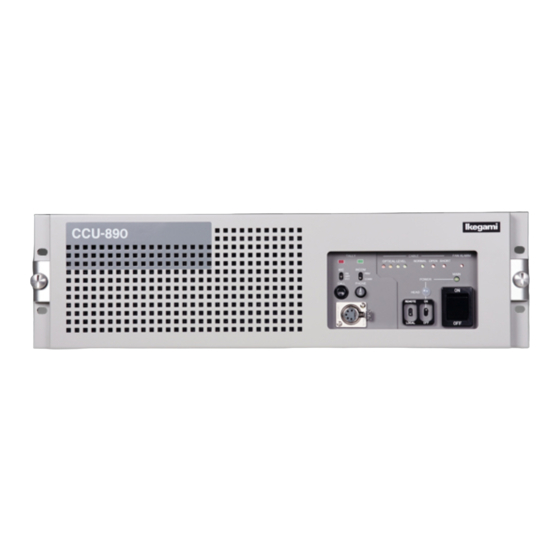
Page 25: Front View
2.1 CCU-890 Front View 2.1 CCU-890 Front View This section explains the names and functions of the parts on the front of the CCU-890. CCU-890 Front View With the Front Cover On INCOM COMMON/PRIVATE switch Front cover CABLE indicator TALLY indicators... - Page 26 ON/OFF from the OCP. * In this case, support status for the power ON/OFF of the camera head and CCU vary according to the OCP to be used. Refer to the instructions accompanying the OCP to be used. CCU-890 0804 VER2 (U) (E)
- Page 27 INCOM connector Connects the intercom headset. The connector type varies according to the specifi cation. CALL switch Only while this switch is pressed, the R TALLY indicators on the camera head and the control panel light. CCU-890 0804 VER2 (U) (E)
-
Page 28: Front View With The Front Cover Off
2.1 CCU-890 Front View CCU-890 Front View With the Front Cover Off CCU MAIN POWER fuse AC line fuses for transmitting power to the camera head Group of modules CCU MAIN POWER fuse Fuse for the CCU main power. Fuse to be used... - Page 29 Test points for DC+5V, +3.3V, +5V, -5V, and GND from the top. Adjustment volumes for each level of QTV Adjustment volumes for QTV2 video level, QTV2 DC level, QTV1 video level, and QTV1 DC level from the top. CCU-890 0804 VER2 (U) (E)
- Page 30 When the PROD line of the system is used for When the PROD line of the system is used for "Clearcom" "RTS" Always place the position of this switch to the lower side. Always place the position of this switch to the lower side. CCU-890 0804 VER2 (U) (E)
-
Page 31: Rear View
2.2 CCU-890 Rear View 2.2 CCU-890 Rear View This section explains the names and functions of the parts on the rear of the CCU-890. TALLY OUT connector CAMERA connector TALLY IN connector Fan motor AUX connector POWER CONT RS422 TRUNK connector (option) - Page 32 Input connector for the trunk line for audio signals to be transmitted to the camera head. MIC OUT connectors Output the audio signals that are input to the MIC IN connectors on the camera head. (2 channels) AC INPUT connector Supplies AC voltage to the CCU. CCU-890 0804 VER2 (U) (E)
-
Page 33: Modules On The Rear Of The Ccu-890
OPTICAL OPTICAL CB-79HD rear view SCAN CONT cable Modules on the Rear of the CCU-890 Modules on the rear are also the slot type and can be removed/inserted as well as the modules on the front. HD RET IN CONT/REF... - Page 34 The same format signals as the HD-SDI OUT 1 output or HD-SDI OUT 2 output can be output. * This product does not have the HD-WFM OUT (HD-SDI video signal output for a waveform monitor) function displayed on the HD-PM OUT2 connector. CCU-890 0804 VER2 (U) (E)
- Page 35 2 channels are used for the input. In this case, the input to the third and fourth channels is disabled. 10. QTV IN connectors Input QTV signals to be transmitted to the camera head (2 channels). Format is SDTV analog composite signal. CCU-890 0804 VER2 (U) (E)
- Page 36 - Signals output from the SYNC OUT connector of another * When the SD RET IN module is installed to this product, CCU-890. However, in this case, select "1080P23." from the QTV IN (QTV signal input) function is disabled for this "SYNC OUT SEL"...
-
Page 37: Chapter 3 Formats And Genlock
FORMATS and GENLOCK FORMATS and GENLOCK... - Page 38 CCU-890 0804 VER2 (U) (E)
-
Page 39: Hdtv Format
2-3 pull down is a method of converting a 24-frame (24P) video into a 60-fi eld (60I) video. 1 frame 1 frame 10 fields (A: odd field, B: even field) Segmented Frame Segmented frame is a method for converting a progressive video separated for 1 line each into an interlaced video. CCU-890 0804 VER2 (U) (E) -
Page 40: Genlock System
When the output format is 1080I/59.94 (2-3 pulldown), 1080P/23.98, or 1080P/23.98 (segment frame), the phase of 23.98P and 2-3 pulldown signals can be synchronized by inputting the following signals. • When the phase of 2-3 pulldown signal of another CCU-890 is synchronized by using a CCU-890 as master HDTV tri-sync signals with 10 FIELD ID output from the SYNC OUT connector of another CCU-890 •... - Page 41 When format conversion is not performed CCU-1 Signal generator CCU-2 termination CCU-3 Condition of signals output by the signal generator in this case A: HDTV tri-sync signals whose format is the same as the camera head or NTSC BBS CCU-890 0804 VER2 (U) (E)
- Page 42 The case that NTSC BBS + 10 FIELD ID (SMPTE 318M-compliant) signals can be supplied from the signal generator CCU-1 Signal generator CCU-2 termination CCU-3 Condition of signals output by the signal generator in this case A: NTSC BBS + 10 FIELD ID (SMPTE 318M-compliant) CCU-890 0804 VER2 (U) (E)
- Page 43 CCU-3 (slave) * In this case, add 10 FIELD ID signals (SMPTE 318M-compliant) to the ENC signal output. (Set the item "10 FIELD ID SIG" of the CCU menu "DOWN CONV CONT (1/3)" to ON.) CCU-890 0804 VER2 (U) (E)
- Page 44 A: HDTV tri-sync signals of 1080I/59.94 format or NTSC BBS B: HDTV tri-sync signals of 1080P/23.98 format (However, the 10-fi eld interval for 1080I/59.94 format needs to be synchronized with the 4-frame interval for 1080P/23.98 format.) CCU-890 0804 VER2 (U) (E)
- Page 45 1080P/23.98 format, or NTSC BBS * In this case, add 10 FIELD ID signals to the signal output for external synchronization. (Set the item "SYNC 2-3ID ADD" of the CCU menu "VIDEO OUT CONT" to ON.) CCU-890 0804 VER2 (U) (E)
-
Page 46: Dual Link (Hs Type) Specifi Cation For The Ccu
The DUAL LINK (HS TYPE) CCU cannot multiplex audio signals to the following outputs. • HD-SDI • HD-SDI PM • HD-SDI WFM Note: For the DUAL LINK (HS TYPE) CCU, a part of the CCU menu and the self diagnostic information is changed. CCU-890 0804 VER2 (U) (E) -
Page 47: Rear Module Confi Guration At Dual Link (Hs Type) Specifi Cation
(When the format selected in "OUT2 FORMAT" is confi rmed, the same format is used for "OUT1 FORMAT.") 3-A. HD-PM OUT connectors [LINK A] Output HD-SDI signals for picture monitor (2 channels). The same format signals as the HD-SDI OUT 1 output or HD-SDI OUT 2 output can be output. CCU-890 0804 VER2 (U) (E) - Page 48 Output video signals for the waveform monitor (2 channels). Only the HD-SDI signals are output. LINK A or LINK B can be selected from "WFM OUT1" and "WFM OUT2" of the CCU menu "VIDEO OUT CONT." DUAL DUAL CCU-890 0804 VER2 (U) (E)
-
Page 49: Video Format Available For Dual Link (Hs Type) Specifi Cation
• 1080P23. Among these formats, "1080I119.,""720P119.," and "1080P59." are called "DUAL format." "1080I119." format can be connected to the BLT video servers. (To be supported) "720P119." format can be connected to the EVS video servers. CCU-890 0804 VER2 (U) (E) - Page 50 CCU-890 0804 VER2 (U) (E)
-
Page 51: Chapter 4 Equipment Connections
EQUIPMENT EQUIPMENT CONNECTIONS CONNECTIONS... - Page 52 CCU-890 0804 VER2 (U) (E)
-
Page 53: Preparation
POWER * HDK-79EX is used as an example of the camera head for explanation. Refer to the instructions accompanying the camera head to be used for the locations of the POWER switches and switch settings. CCU-890 0804 VER2 (U) (E) -
Page 54: Power Supply
To the camera Power outlet This completes the connection procedure for supplying power from the CCU-890 to the camera. Two methods of power supply to the camera head are available with this confi guration. a) To control the power ON/OFF from the CCU... - Page 55 MAIN POWER switch HEAD POWER indicator HEAD POWER switch POWER LOCAL/REMOTE switch Setting the HEAD POWER switch on the front of the CCU to "ON/OFF" enables control of the power supply to the camera head. CCU-890 0804 VER2 (U) (E)
- Page 56 Some OCP does not have the P.S CONT connector. When an OCP that does not have the P.S CONT connector is used, only ON/OFF of the power supply for the camera head is controlled without controlling the power ON/OFF of the CCU. CCU-890 0804 VER2 (U) (E)
-
Page 57: Ccu And Camera Head Connection
4.3 CCU and Camera Head Connection 4.3 CCU and Camera Head Connection This section explains how to connect the CCU-890 to the camera. Connect the CAMERA connector on the rear of the CCU to the CAMERA connector on the camera head via a camera cable. -
Page 58: System Setup Diagram
Headset (ENG/PROD) HDK-79EX * HDK-79EX is used as an example of the camera for explanation. Headset (ENG/PROD) CCU-890 CSU-110 Multiple Camera Operation * When the OCP-200 is used, the maximum CP cable length is 80m. CCU-890 0804 VER2 (U) (E) - Page 59 MCP-200 OCP-200 *1 The CCU-890 can be operated when the network ID of the rotary switch on the PULSE module on the front of the CCU corresponds to the CCU No. set by an OPC or MCP. *2 For the maximum and minimum extension length of the cables, refer to "BSH-200/CPH-200 Setup Manual."...
-
Page 60: Operating Systems
4.5 Operating Systems 4.5 Operating Systems You can choose and operate each control panel to be connected to the CCU-890, for your purpose. Example of Standard Configuration (1 camera head) Camera head WFM CONT COMM Example of Configuration Up to 8 Camera Heads... - Page 61 WFM CONT MCP/CCP IN-1 COMM AC IN IN-8 CCU-8 PM, WFM, MCP/CCP CSU-1 AC IN CCU-9 IN-1 IN-8 CCU-16 CSU-2 CCU-17 IN-1 IN-8 CCU-24 CSU-3 CCU-25 IN-1 IN-8 CCU-32 CSU-4 CCU-33 IN-1 IN-8 CCU-40 CSU-5 CCU-890 0804 VER2 (U) (E)
- Page 62 4.5 Operating Systems Network Connection (Basic bus connection) This connection confi guration is available only for network-enabled CCU/BS such as the CCU-890. termination Coaxial cable CPH-200 CCU-1 CCU-2 CP cable termination OCP-200 MCP-200 Note: - The OCP/CCP connector and MCP/CCP connector on the CCU cannot be used with the network connector at the same time in this confi...
-
Page 63: External Connections
AC voltage (C) supplied from CCU to the camera head AC (H) AC voltage (H) supplied from CCU to the camera head MTL H - C Control signal Camera -> CCU MTL C - H Control signal CCU -> Camera CCU-890 0804 VER2 (U) (E) - Page 64 Camera head power ON/OFF control signal input N . C N . C N . C N . C PWR CONT (C) CCU power ON/OFF control signal input (C)) Ground for camera head power ON/OFF control signal CCU-890 0804 VER2 (U) (E)
- Page 65 : XLR-3-12C (3-pin male plug) or equivalent Insertion Side Pin No. Name Function External Interface SHIELD Shield for AUDIO TRUNK signal AUD T IN (H) AUDIO TRUNK (H) line balanced input AUD T IN (C) AUDIO TRUNK (C) line balanced input CCU-890 0804 VER2 (U) (E)
- Page 66 G TALLY signal input (+) N . C N . C TALLY COM Ground for R TALLY signal input or G TALLY signal input When only one external line is provided, the ENG line is used. CCU-890 0804 VER2 (U) (E)
- Page 67 REMOTE ISOLATE ON/OFF for REMOTE ISOLATE OFF: OPEN, ON: GND N. C N. C N. C N. C N. C When the intercom system to be connected is one line, the ENG line is used. CCU-890 0804 VER2 (U) (E)
- Page 68 TR1 OUT (-) TR1 IN (+) Digital data input (+) IN (S) SHIELD N . C OUT (S) SHIELD Digital data output (+) TR1 OUT (+) TR1 IN (-) Digital data input (-) Ground for input/output signal CCU-890 0804 VER2 (U) (E)
- Page 69 Control signal output Ground for control signal output N . C (OUT) N . C WFM CT4 Control signal output WFM CT5 Control signal output Control signal output WFM CT6 Control signal output WFM CT7 CCU-890 0804 VER2 (U) (E)
- Page 70 - Set the tally input mode (MAKE/POWER) by the switch on the AUX-A module. - HPIND function is output from the open collector. Note: Y TALLY only supports contact supply (MAKE). Power supply (POWER) is currently not supported. CCU-890 0804 VER2 (U) (E)
- Page 71 TALLY GND Ground for TALLY signal - Select one from Y TALLY output or COMMON TALLY output for the pin C. Use of COMMON TALLY OUT enables to control both R TALLY and G TALLY simultaneously. CCU-890 0804 VER2 (U) (E)
- Page 72 STAIR signal output SEQ ON Output of control signal which selects SEQ -15 V RET -15 V RET voltage Ground for WFM control signal EXPAND Ground for EXPAND control signal -15 V IN -15V input voltage CCU-890 0804 VER2 (U) (E)
- Page 73 RECALL 1 RECALL 4 PRC03 - 12A10 - 7M10.5 REMOTE SYNC IN STORE PRESET 4 PRESET 1 PRESET 2 PRESET 3 DA-15P : JAE or AMP DA-C1-J10-36 (HOOD) : JAE or 206471-1 (HOOD) : AMP CCU-890 0804 VER2 (U) (E)
- Page 74 RGB STAIR CASE -12 V 1 FLD X5 VERT R - Y (V AXIS) SEL 1 LINE (1H) RGB ENABLE DB - 25S - N DB - C2 - J9 - S6 (HOOD) (DB - 25P) CCU-890 0804 VER2 (U) (E)
- Page 75 -X AUDIO IN +X AUDIO IN +TIME CODE IN -TIME CODE IN PRESET1 PRESET2 PRESET3 PRESET4 PRESET5 PRESET6 PRESET7 PRESET8 STORE DB - 25P - N DB - C8 - J10 - B2-1 (HOOD) (DB - 25S) CCU-890 0804 VER2 (U) (E)
- Page 76 TRIAX ON CCU triax specification control signal (ON: GND) N . C +12 V DC +12V power output Ground for DC +12V power output - TRIAX ON for the pin J is an optional function. CCU-890 0804 VER2 (U) (E)
- Page 77 +12 V DC +12V power output for control panel +12 V RET DC +12V power RET INC C-CP Audio signal output from CCU to control panel INC CP-C Audio signal input from control panel to CCU CCU-890 0804 VER2 (U) (E)
- Page 78 CCU-890 0804 VER2 (U) (E)
-
Page 79: Ccu Settings And Adjustment
CCU SETTINGS CCU SETTINGS and ADJUSTMENT and ADJUSTMENT... - Page 80 CCU-890 0804 VER2 (U) (E)
-
Page 81: Settings From The Ccu Menu
5.1 Settings from the CCU Menu 5.1 Settings from the CCU Menu The menu operation for the CCU-890 is performed from the MCP or OCP. The setting of each item is performed by displaying the main menu/submenu screen on the PM screen. -
Page 82: Exiting The Menu
This section explains how to exit the main menu/submenu on the PM screen. Exit the menu screen in the following two ways: a) Select "QUIT" on the CCU main menu and press the CALL button. b) Press the BARS button. The main menu/submenu disappears. CCU-890 0804 VER2 (U) (E) -
Page 83: Basic Operation Of The Menu (Operation From The Ocp-200)
The menu screen (Fig.3) appears on the LCD, and the CHARACTER main menu screen appears on the PM. Scene File Menu Camera ID Name Fig.2 CHARACTER Scene File Menu Camera ID Name Menu Quit Enter Select Next Fig.3 (Menu screen) CCU-890 0804 VER2 (U) (E) - Page 84 This section explains how to exit the main menu/submenu on the PM screen. Exit the menu screen in the following ways: a) Select "QUIT" on the CCU main menu. b) Press the QUIT button on the LCD. c) Press the BARS button on the OCP. CCU-890 0804 VER2 (U) (E)
-
Page 85: Menu Confi Guration
5.1 Settings from the CCU Menu Menu Confi guration The following lists the CCU-890 menu confi guration. Menu for the standard specifi cation and menu for the DUAL LINK (HS TYPE) specifi cation are available. Reference: For the menu for the DUAL LINK (HS TYPE) specifi cation, refer to "... - Page 86 QUIT..............Returns to the main menu. MODULE SW............Displays the switch setting status of the PULSE module and CONT/REF module. ROM VERSION ........... Displays the ROM version. CHECK SUM ............Displays the ROM check sum. CCU-890 0804 VER2 (U) (E)
-
Page 87: Bars Title
IRIS control knob to position settings. the fl ashing cursor on the submenu "HD/DC/UC/VID/AUD CONT," and press the fl ashing cursor on "HDTV CONT (1/2)," and press the CALL button. the CALL button. CCU-890 0804 VER2 (U) (E) - Page 88 The phase difference between the video signal sent from the camera head and the SYNC signal of the video signal sent from the CCU-890 is delayed at least +6H to +8H. In this setting, when you switch the HDTV format signal to the return signal, the image on the viewfi nder is less scrambled due to the switching.
-
Page 89: Hdtv Pm Display1
SIDE MASK MARKER Does not display the side mask marker. Displays the side mask marker. (SIDE MASK Selects the side mask marker width. MARKER) WIDTH (The width gets wider in the order of 5CK<10CK<15CK<20CK.) 10CK 15CK 20CK CCU-890 0804 VER2 (U) (E) -
Page 90: Hdtv Cont (2/2)
*1 When "SLIM DTL" is "OFF" or SLIM DTL is set to be effective only in the horizontal direction ("H ONLY" is set to "HV SLIM DTL TYPE"), the frequency to boost is half the number of effective lines. *2 This item is valid only when the camera head to be connected is the HDK-790EX or HDK-790EX . CCU-890 0804 VER2 (U) (E) -
Page 91: Down Conv Cont (1/3)
*2 When "SLIM DTL" is "OFF" or SLIM DTL is set to be effective only in the horizontal direction ("H ONLY" is set to "HV SLIM DTL TYPE"), the frequency to boost is half the number of effective lines. *3 This item is valid only when the camera head to be connected is the HDK-790EX or HDK-790EX . CCU-890 0804 VER2 (U) (E) -
Page 92: Down Conv Cont (2/3)
Sets the horizontal phase of the analog GBR signal. PHASE ADJ PM -336 to 336 Sets the horizontal phase of the PM (digital) signal. PHASE ADJ WFM -336 to 336 Sets the horizontal phase of the WFM (digital) signal. CCU-890 0804 VER2 (U) (E) -
Page 93: Down Conv Cont (3/3)
Sets the background level of characters on the SD-PM. PM DISPLAY1 — Sets the SD-SDI PM output display. Selecting this item switches to "SDTV PM DISPLAY1." PM DISPLAY2 — Sets the SD-SDI PM output display. Selecting this item switches to "SDTV PM DISPLAY2." CCU-890 0804 VER2 (U) (E) -
Page 94: Sdtv Pm Display1
*1 When "SCREEN MODE" is set to "4:3," only "OFF" or "ON-4:3" can be selected for "FRAME MARKER," "ACTION MARKER," and "TITLE MARKER." *2 When "SCREEN MODE" is set to "4:3," "SIDE MASK" is fi xed to "OFF." CCU-890 0804 VER2 (U) (E) -
Page 95: Up Conv Cont (1/2)
Suitable for shooting from a helicopter. Neither afterimages nor images remain because fi led handling is done. SPORTS Suitable for broadcasting quick-motion sports. OUT SEL MONO Sets image output in black and white. COLOR Sets image output in color. CCU-890 0804 VER2 (U) (E) -
Page 96: Up Conv Cont (2/2)
(DTL) H CORING 0 to 255 Sets the horizontal coring of DTL. (DTL) V CORING 0 to 255 Sets the vertical coring of DTL. (DTL) H BOOST FREQ 18M Sets the horizontal boost frequency of DTL. CCU-890 0804 VER2 (U) (E) -
Page 97: Video Out Cont
Sets not to embed pulse signals, which counted 1 to 5 frames, in the SYNC output. Sets to embed pulse signals, which counted 1 to 5 frames, in the SYNC output. WFM OUT SEL Sets the WFM outputs. CCU-890 0804 VER2 (U) (E) -
Page 98: Wfm Out Sel
WFM HDTV FMT OUT1 Sets the same format as HD-SDI output1 when "HDTV" is selected for the WFM output. OUT2 Sets the same format as HD-SDI output2 when "HDTV" is selected for the WFM output. CCU-890 0804 VER2 (U) (E) -
Page 99: Audio Cont
Sets the amount of delay of the MIC output (2 channels). SETTING SELECT SETTING SELECT registers/calls settings. (* USA option) Setting Item Set Value Description STORE Registers/calls set values for each menu item. NUMBER Selects the registration/call number. NO.1 to NO.8 CCU-890 0804 VER2 (U) (E) -
Page 100: Ret Video Format
RET VIDEO FORMAT, and then "SDI" or "VBS" can be selected from SDTV TYPE. However, when FRAME SYNCHRO is set to "ON," the setting of RET VIDEO FORMAT is fi xed to "SDI," and the item for SDTV TYPE is not displayed. CCU-890 0804 VER2 (U) (E) -
Page 101: Information
CALL button. CALL button. CALL button. When "CONT/REF" is selected When "PULSE" is selected The DIP switch settings of the CONT/REF The DIP switch settings of the PULSE module module are displayed. are displayed. CCU-890 0804 VER2 (U) (E) -
Page 102: Others (1/2)
When the camera head menu screen exits, "OFF" is set automatically. Reference: For the details of ARIB-standard color bar, see the standard (ARIB STD-B28). For the details of SMPTE-standard color bar, see the standard (RP 219-2002). CCU-890 0804 VER2 (U) (E) -
Page 103: Others (2/2)
*2 For the camera program numbers, refer to the instructions accompanying the control panel such as the OCP-200 that supports the camera program numbers. *3 The setting for the camera program numbers is enabled when CAM PGM NO. ENA is set to "ON." CCU-890 0804 VER2 (U) (E) - Page 104 5.1 Settings from the CCU Menu CCU Menu with/without Installing Modules Depending on the installation of the SDTV PROC module and SDTV RET module on the front of the CCU-890, the display of the CCU menu varies as shown below.
- Page 105 FRAME SYNCHRO ..........Sets ON/OFF of the frame synchronization function. RET1 VIDEO FORMAT ........Sets the format of the return signal input to the camera head. RET2 VIDEO FORMAT RET3 VIDEO FORMAT RET4 VIDEO FORMAT V PHASE..............Sets the vertical phase. CCU-890 0804 VER2 (U) (E)
- Page 106 QUIT..........Returns to the submenu OTHERS. CAM PGM NO. ENA ....Sets whether the CCU manages the camera program numbers. CAM PGM NO. SET ....Sets how to display the camera program numbers for the camera head and control panel. CCU-890 0804 VER2 (U) (E)
-
Page 107: Hdtv Cont (1/2)
IRIS control knob to position various settings. the fl ashing cursor on the submenu the fl ashing cursor on "VIDEO OUT CONT "HD/DC/UC/VID/AUD CONT," and press (DUAL)," and press the CALL button. the CALL button. CCU-890 0804 VER2 (U) (E) - Page 108 1080P23. -1375 to 1375 -563 to 563 720P59. -825 to 825 -375 to 375 *3 When all items other than "1080I59." are selected for "OUT1 FORMAT"/"OUT2 FORMAT" in "HDTV CONT (1/2)," selecting ON/OFF is enabled. CCU-890 0804 VER2 (U) (E)
-
Page 109: Audio Cont
Sets the amount of delay for the audio signals of HDTV channels. DIGITAL DELAY 0 to 21 Sets the amount of delay of the digital audio output. MIC1/2 OUT DELAY 0 to 21 Sets the amount of delay of the MIC output (2 channels). CCU-890 0804 VER2 (U) (E) -
Page 110: Settings Using Switches On The Module
Sets the G TALLY signal input to the CCU to "MAKE/BREAK mode." Y TALLY POWER Sets the Y TALLY signal input to the CCU to "POWER mode." MAKE Sets the Y TALLY signal input to the CCU to "MAKE/BREAK mode." * Currently, S3 supports "MAKE" only. CCU-890 0804 VER2 (U) (E) -
Page 111: Intercom Settings
Sets to "ON" when the PROD line of the system is used for "RTS" or "clearcom." PROD RTS Sets to "OFF" when the PROD line of the system is used for "RTS." -15dB ON Sets to "ON" when the PROD line of the system is used for "clearcom." CCU-890 0804 VER2 (U) (E) -
Page 112: Pgm Settings
Sets to "-20dB" when the input level of the PGM-3 is "-20dB." AUDIO TRUNK LEVEL Sets to "0dB" when the input level of the AUDIO TRUNK is "0dB." -20dB Sets to "-20dB" when the input level of the AUDIO TRUNK is "-20dB." CCU-890 0804 VER2 (U) (E) -
Page 113: Trouble Shooting And Maintenance
TROUBLE SHOOTING TROUBLE SHOOTING and MAINTENANCE and MAINTENANCE... - Page 114 CCU-890 0804 VER2 (U) (E)
-
Page 115: Indicator On The Front Of Ccu Lights
The FAN ALARM indicator lights when any of the fans (three in total) Check if the fans are normal. inside the CCU stops. If any of the fans is abnormal or the lifetime of the fan expires, replace it with a new one. CCU-890 0804 VER2 (U) (E) - Page 116 Clean the four sections: receptacle on the camera head, plug receptacle on the CCU, and plug/jack on both ends of the camera cable. The cleaning method for male connectors slightly differs from that for female connectors. CCU-890 0804 VER2 (U) (E)
- Page 117 Be sure to push the top securely into the connector. Tighten the screw with a fl at-blade screwdriver or a coin. Male connectors have no "top"; therefore, steps 1, 2, and 6 above are not required. CCU-890 0804 VER2 (U) (E)
- Page 118 8 to 10 turns. The extractor is removed from the alignment sleeve. Male connectors have neither "top" nor "alignment sleeve"; therefore, steps 1 to 3 and 8 above are not required. CCU-890 0804 VER2 (U) (E)
-
Page 119: Alarm Indicator On The Control Panel Flashes On And Off
ON and OFF The CCU-890 is equipped with a self diagnostic function which monitors whether the CCU and camera head are running normal. As soon as the CCU power is turned ON, the self diagnostic function starts running, and always runs during operation. -
Page 120: Ccu Self Diagnostic Information
Light cannot be received. Cable Camera cable connection status between Normal Connection the camera head and the CCU OPEN Cable is not connected, or there is an open. SHORT A short circuit occurs in the cable. CCU-890 0804 VER2 (U) (E) - Page 121 LB 13:9 Letterbox 13:9 UC Screen Screen mode status of up converted signal The aspect ratio is 4:3 16:9 The aspect ratio is 16:9 LB 16:9 Letterbox 16:9 LB 14:9 Letterbox 14:9 LB 13:9 Letterbox 13:9 CCU-890 0804 VER2 (U) (E)
- Page 122 Power Tap Transformer tap number in the CCU for 1, 2, 3, 4 Tap number used for the power being transmitting power to the camera head transmitted. The higher the number, the higher the voltage. CCU-890 0804 VER2 (U) (E)
- Page 123 DUAL LINK (HS TYPE) specifi cation.) UC Screen Screen mode status of up converted signal The aspect ratio is 4:3 16:9 The aspect ratio is 16:9 LB 16:9 Letterbox 16:9 LB 14:9 Letterbox 14:9 LB 13:9 Letterbox 13:9 CCU-890 0804 VER2 (U) (E)
- Page 124 The lighting state of the OPTICAL indicator on the front of the CCU indicates the worse state as this self diagnostic information display. When both states are the same, the lighting state indicates the strength of the optical level. CCU-890 0804 VER2 (U) (E)
-
Page 125: Replacing Fuses
CAUTION: Use specifi ed fuses or equivalent ones. For fuses that can be used, refer to "CCU-890 Front View With the Front Cover Off" (page 14). Make sure the MAIN POWER switch on the front of the CCU is turned "OFF."... - Page 126 CCU-890 0804 VER2 (U) (E)
-
Page 127: Changing Information
CHANGING INFORMATION CHANGING INFORMATION CHANGING INFORMATION This chapter contains the revision information of user-specifi c specifi cation or design change requested by users. Read by comparing this information with the main part of the maintenance manual. CCU-890 0804 VER2 (U) (E) - Page 128 CCU-890 0804 VER2 (U) (E)
- Page 129 Ikegami Tsushinki Co., Ltd. - All rights reserved. Reproduction or duplication, without permission of Ikegami Tsushinki Co., Ltd. of editorial or pictorial content in whole or in part, in any manner, is prohibited. - Specifi cations and design are subject to change without prior notice.
- Page 132 37 Brook Avenue, Maywood, New Jersey 07607, U.S.A. Phone: (201) 368-9171, Telex: 219034 ITCNJ UR, Fax: (201) 569-1626 Ikegami Electronics (Europe) GmbH Ikegami Strasse 1, 41460 Neuss 1, F.R. Germany Phone: (02131) 123-0, Telex: 17-2131365=IKE, Fax: (02131) 102820 Property of :...
Need help?
Do you have a question about the CCU-890 and is the answer not in the manual?
Questions and answers