Table of Contents
Advertisement
Quick Links
Advertisement
Table of Contents

Related Manuals for Rocktron REPLIFEX


Summary of Contents for Rocktron REPLIFEX
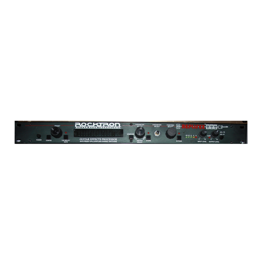
- Page 1 ™ User's Manual ® HUSH ® licensed by May be covered by one or more of the following: U.S. Patents #4538297, 4647876, 4696044, 4745309, 4881047, 4893099, 5124657, 5263091, 5268527, 5319713 and 5333201. Other patents pending. Foreign patents pending.
- Page 2 Do not expose this unit to excessive heat. This unit is designed to operate between 32° F and 104° F (0° C and 40° C). This unit may not function properly under extreme temperatures. Copyright ©1995 Rocktron Corporation. All rights reserved.
- Page 5 SELECTING A PRESET STEP 1 Turn the PRESET control to select the desired preset. The new preset will be recalled automatically. CHANGING PRESET PARAMETERS STEP 2 Turn the FUNCTION SELECT control to the desired effect or utility function. STEP 3 Turn the PARAMETER SELECT control to the parameter you wish to alter under the selected effect or utility function.
- Page 6 POWER switch CONFIG button/led This button briefly displays which configuration the current preset ™ uses. After displaying the configuration, the Replifex will display the current preset number and title. PRESET control This control scrolls through and instantly recalls the successive presets.
- Page 7 (c) the parameter is returned to its original value. STORE button/led ™ This button is used to store parameter values into the Replifex memory when altered. See "Storing Changed Preset Parameters" in Chapter 7 for more information on this procedure. PARAMETER SELECT control When adjusting parameter values, this control will scroll through the available parameters under the current function heading.
- Page 8 REFERENCE LEVEL switch This switch adjusts the output range of the unit and may be set at ™ either -10dB or +4dB. When using the Replifex with professional studio equipment providing a nominal input level of +4dB, it is recommended that the +4 setting is used for best results. If the ™...
- Page 9 PHANTOM POWER jack This 2.5mm PIN jack offers the ability to power Rocktron MIDI foot controllers from a 7-pin MIDI cable which connects from the Rocktron MIDI foot controller to the MIDI IN jack on the rear ™ panel of the Replifex .
- Page 10 MIDI devices). Pins 6 and 7 of this connector carry phantom power to power a Rocktron MIDI foot controller when a 7-pin MIDI cable is used. This connector is also provided for the connection of a Rocktron ™ All Access MIDI footswitch, which can be configured as a ™...
- Page 13 Connections...
- Page 14 Classic configuration provides these effects: ® • HUSH • Reverb • Delay • Parametric EQ • Compression • Phaser • Flanger • Tremolo • Pitch Shift • Chorus • Auto Pan • Speaker Simulator Rotary configuration provides these effects: • HUSH ®...
- Page 15 Block Diagrams...
- Page 16 Block Diagrams...
- Page 17 Functions and Parameter Descriptions Replifex ™ Functions and Parameter Descriptions Step 3: Step 2: Step 1: Turn to alter the value of the Turn to select a parameter Turn to select a function. selected parameter. within the selected function.
- Page 18 DIRECT The DIRECT parameter determines whether the direct signal is switched in or out of the signal path. When using the Replifex™ in applications where the unit is connected in parallel, it is recommended that the direct signal is switched out - thereby providing 100% wet...
- Page 19 Functions and Parameter Descriptions Function The PARAMETER SELECT control will allow you to access each of the following Mixer parameters: LEFT DIR The LEFT DIRECT parameter determines the level of the direct signal of the current preset at the left output. RIGHT DIR The RIGHT DIRECT parameter determines the level of the direct signal of the current preset at the right output.
- Page 20 Functions and Parameter Descriptions Function The PARAMETER SELECT control will allow you to access each of the following Hush parameters: ® HUSH I/O The HUSH I/O parameter determines whether the HUSH circuit is active or bypassed for the current preset. EXP THRESH The EXPANDER THRESHOLD parameter determines the level at which downward expansion begins.
- Page 21 Functions and Parameter Descriptions Function The PARAMETER SELECT control will allow you to access each of the following Compressor parameters: COMPRESR I/O The COMPRESSOR I/O parameter determines whether the compres- sion circuit is active or bypassed for the current preset. COMP THRESH The COMPRESSOR THRESHOLD parameter determines the input level (in dB) at which compression will begin.
- Page 22 Functions and Parameter Descriptions Function The PARAMETER SELECT control will allow you to access each of the following EQ parameters: EQ I/O The EQ I/O parameter determines whether the EQ circuit is active or bypassed for the current preset. BASS LVL The BASS LEVEL parameter allows you to cut or boost the low frequencies by up to 15dB.
- Page 23 DELAY LVL The DELAY LEVEL parameter determines the overall level of the ™ delayed signal at the output of the Replifex D-MIX S1/S2 The D-MIX S1/S2 parameter defines the ratio of Source 1 signal to Source 2 signal to be input to the Delay section. Source 1 is the Voice 1 output from the previous effect in the signal chain (chorus, flanger, pitch shifter, etc.), while Source 2 may be the Voice 2 output from the...
- Page 24 Functions and Parameter Descriptions SOURCE 2 This parameter is used to select whether the Source 2 input will be the VOICE 2 output from the previous effect in the signal chain or the direct signal. In configurations where there is no effect immediately preceding the delay, both Source 1 and Source 2 will be the direct signal.
- Page 25 The REVERB LEVEL parameter allows you to control the level of the preset will be changed to ™ reverb signal at the output of the Replifex relative to the direct signal match those of the previous and other effect signals.
- Page 26 The TIME parameter determines the multiplier by which a new modulation rate will be selected for the RATE parameter when the Tap ™ Delay feature of the Replifex is used. (See Section 7: "Tap Delay" for more information on the Tap Delay feature.)
- Page 27 (See Section 7: "Tap Delay" for more information on the Tap Delay feature.) PHASER LVL The PHASER LEVEL parameter allows you to control the level of the phaser signal at the output of the Replifex™ relative to the direct signal and other effect signals.
- Page 28 The TIME1 parameter determines the multiplier by which a new modulation rate will be selected for the RATE 1 parameter when the ™ Tap Delay feature of the Replifex is used. (See Section 7: "Tap Delay" for more information on the Tap Delay feature.)
- Page 29 The TIME 1 parameter determines the multiplier by which a new modulation rate will be selected for the RATE 1 parameter when the Tap Delay feature of ™ the Replifex is used. CRS OUT 2 The CHORUS OUTPUT 2 parameter determines the volume of Voice 2.
- Page 30 The PITCH SHIFT PAN parameter allows you to pan the shifted signal to the left or right channel. PITCH The PITCH parameter selects what harmony note the Replifex ™ will produce based on the input note. The value displayed for this parameter represents the number of cents that the signal will be shifted (adjustable in 20-cent increments).
- Page 31 NOTE: There are 5 steps of the parameter adjust control between each of the intervals shown above (each step equals 20 cents).This allows for smooth pitch change when an expression controller (such as a volume pedal used with a Rocktron All Access ™...
- Page 32 TIME The TIME parameter determines the multiplier by which a new modulation rate will be selected for the RATE parameter when the Tap Delay feature of the Replifex ™ is used. (See Section 7: "Tap Delay" for more information on the Tap Delay feature.)
- Page 33 Functions and Parameter Descriptions Function The PARAMETER SELECT control will allow you to access each of the following Rotary Speaker parameters: ROTR SPK I/O The ROTR SPK I/O parameter determines whether the simulated speaker is rotating or not. *For added versatility ROT SPEED The ROTATION SPEED parameter switches between the SLOW when using continuous...
- Page 34 Functions and Parameter Descriptions The PARAMETER SELECT control will allow you to access each of the following Function Speaker Simulator parameters: SPKR SIM I/O The SPEAKER SIMULATOR I/O parameter determines whether the speaker simulator circuit is active or bypassed for the current preset. SPKR TYPE The SPEAKER TYPE parameter determines the type of speaker to be simulated.
- Page 35 Functions and Parameter Ranges (The actual functions displayed are configuration-dependent) OUTPUT Stereo, Mono -10dB to +30dB HUSH OFFSET Out, In MUTE Out, In DIRECT - to +6dB LEFT DIR - to +6dB RIGHT DIR - to +6dB EFFECT LEVEL DIRECT Pre, Post Direct<0 to 100>Effect PHS DIR/EFF...
- Page 36 Functions and Parameter Ranges DLY TIME1 0ms to 1000ms FINE 1 0ms to 9ms DLY RGN 1 - to 0dB DELAY OUT 2 - to 0dB DLY PAN2 Left<0 to 100>Right DLY TIME2 0ms to 1000ms FINE 2 0ms to 9ms DLY RGN 2 - to 0dB D>SPILLOVER...
- Page 37 Functions and Parameter Ranges CHORUS I/O Out, In CRS OUT 1 - to 0dB CRS PAN 1 Left<0 to 100>Right CRS DPTH 1 0 to 100 CRS RATE 1 0 to 254 CRS>DLY1 0ms to 148ms TIME1 32nd, 16th, 8th, Triplet, ¼, ½, or None CRS OUT 2 - to 0dB CRS PAN 2...
- Page 38 Step 1 Turn the PRESET control to the desired preset you wish to recall. The selected preset will be recalled automatically.
- Page 39 ™ Operating the Replifex Step 1 Turn the FUNCTION SELECT control to select the function heading which contains the parameter(s) you wish to change. Step 2 Turn the PARAMETER SELECT control to the specific parameter you wish to change. Step 3 Turn the PARAMETER ADJUST control to alter the parameter value.
- Page 40 Use the PARAMETER ADJUST control to select the on/off condition of Channel Switch 1. Step 3 ™ When switched "ON", the channel connected to the Tip of the Replifex CHANNEL SWITCH jack will be switched when the current preset is recalled.
- Page 41 Use the PARAMETER ADJUST control to select the on/off condition of Channel Switch 2. ™ When switched "ON", the channel which is connected to the Ring of the Replifex CHAN- NEL SWITCH jack will be switched when the current preset is recalled.
- Page 42 ™ Operating the Replifex Step 1 To begin the Title Edit function, turn the FUNCTION SELECT control clockwise until the ™ Replifex displays "TITLE EDIT". Step 2 Turn the PARAMETER SELECT control clockwise to initiate the Title Edit mode. Turning this control will also select the character location to be edited.
- Page 43 STORE button will erase any editing that was done in Title Edit. ™ Also, after flashing "STORED", the Replifex will remain in the Title Edit mode. You may either (a) turn the PRESET control to display and edit other preset titles without having to exit and re-enter Title Edit, or (b) turn the FUNCTION SE- LECT control to exit the Title Edit mode.
- Page 44 ™ Operating the Replifex 3,6,9,12 2,5,8,11 4,7,10,13 To access the Controller Assign function, turn the FUNCTION SELECT control clockwise to Step 1 "CONTROLLER ASSIG". Turn the PARAMETER SELECT control for the first parameter of the Controller Assign Step 2 function. This parameter allows you to select a controller number for the "CTR A" (Controller A) parameter to respond to.
- Page 45 Turn the PARAMETER ADJUST control to scroll through the available parameters for the current configuration. Step 7 After selecting the parameter that you which to assign to a controller, press the STORE button ™ to save it. The Replifex will flash "STORED" briefly.
- Page 46 ™ Operating the Replifex ™ Note: The Replifex allows you to select an upper and lower value limit which the parameter cannot exceed. For example, if a parameter has a value range from - to 0dB, yet you would like the range of the parameter to vary from only -12dB to -2dB, you may set a lower limit of -12 and an upper limit of -2 via the Upper and Lower Limit parameters.
- Page 47 ™ Operating the Replifex Use the PARAMETER ADJUST control to select the lowest value which the parameter is not Step 12 to fall below through MIDI control changes. After selecting a value for the lower limit, press the STORE button to save it. "STORED" will Step 13 flash briefly on the display.
- Page 48 ™ Operating the Replifex Copying presets: Step 1 Turn the FUNCTION SELECT control to "COPY". Step 2 Turn the PARAMETER SELECT control one step clockwise to access the "PR> XX to >PR XX" parameter, as shown below. The number on the left represents the preset to be copied, while the number on the right represents the preset location to copy to.
- Page 49 "COPY TITLE TOO?". This allows you to copy the title from the copied preset into the new location as well. To copy the title, press the STORE button a second time. "STORED" will flash briefly before the Replifex ™...
- Page 50 Use the PARAMETER ADJUST control to select the location to copy the controller assign- ments into. Step 5 Press the STORE button to copy the selected preset into the selected preset location. "STORED" will flash briefly before the Replifex™ displays the preset number and title that the controller assignments were stored into.
- Page 51 Note 2: If a footswitch is connected to the rear panel Tap Delay/Rate FOOTSWITCH ™ jack when the unit is powered up, the Replifex will automatically determine the type of footswitch connected (i.e. normally open, normally closed, etc.). However, the footswitch must already be connected when the unit is turned on.
- Page 52 ™ Operating the Replifex 2,5,6 Step 1 To access MIDI Program Mapping, turn the FUNCTION SELECT control clockwise until the ™ Replifex displays "PROGRAM CHANGES". Step 2 Turn the PARAMETER SELECT control one step clockwise to display the current Program Change On/Map/Off status.
- Page 53 ™ Operating the Replifex Step 5 If "MAP" has been selected, turn the PARAMETER SELECT control one step clockwise to display the current Program Changes mapping assignments. Step 6 The number on the left of the display is the MIDI program number (or the number sent via a MIDI footswitch or other MIDI transmitter).
- Page 54 ™ Operating the Replifex Step 1 ™ Turn the FUNCTION SELECT control clockwise until the Replifex displays "MIDI CHAN- NELS". Step 2 Turn the PARAMETER SELECT control one step clockwise to display the current MIDI Receive channel. Step 3 Turn the PARAMETER ADJUST control to select the desired MIDI channel. You may select channels 1-16, OMNI (all channels) or OFF (will not receive MIDI commands).
- Page 55 Operating the Replifex Step 6 ™ Turn the PARAMETER ADJUST control to select the channel that the Replifex will trans- mit a MIDI program change on. You may select channels 1-16 or OFF (will not transmit a MIDI program change).
- Page 56 Connect a standard MIDI cable from the MIDI OUT of the transmitting Replifex to the Step 1 MIDI IN on the receiving Replifex ™ IMPORTANT: Do not allow a looping connection from the MIDI OUT/THRU of the receiving Replifex ™ ™ back to the MIDI IN of the transmitting Replifex Step 2 Turn the FUNCTION SELECT controls on both the transmitting and receiving Replifexes until "MIDI DUMP/LOAD"...
- Page 57 "RECEIVING..." while it receives and stores the preset parameters and title. TRANSMITTING REPLIFEX RECEIVING REPLIFEX After all the information for the dumped preset is stored, the receiving Replifex ™ will display ™...
- Page 58 Replifex can receive it. Also, make sure that the sequencer's MIDI filter is set to accept SYSX information. Connect a standard MIDI cable from the MIDI OUT of the transmitting Replifex ™ to the Step 1 MIDI IN on the receiving sequencer.
- Page 59 ™ After the Replifex displays "TRANS COMPLETE", stop the sequencer. The sequencer should have recorded all of the data that was dumped from the Replifex ™ . Keep this data stored on a disk in a safe place. Turn the PARAMETER SELECT control to continue.
- Page 60 Step 1 ™ MIDI IN on the receiving Replifex IMPORTANT: Do not allow a looping connection from the MIDI OUT/THRU of the receiving Replifex ™ back to the MIDI IN of the transmitting sequencer. Turn the FUNCTION SELECT controls on both the receiving Replifex ™...
- Page 61 Only the transmission string where the error occurred is corrupted. ™ When receiving a Bulk Load, it is important that the data loaded to the Replifex is not transmitted faster than it was originally dumped from the Replifex ™...
- Page 62 ™ Operating the Replifex Restoring a single factory preset: Step 1 Turn the FUNCTION SELECT control clockwise to "FACTORY RESTORE". Step 2 Turn the PARAMETER SELECT control one step clockwise to "RESTR 1 TO 1". The number on the left is the original factory preset number to be restored. The number on the right is the preset location that the preset will be stored into.
- Page 63 Press the STORE button to begin restoring the selected preset into the selected location. After the process is completed, the display should read "ERRORS 0". This represents the number ™ of bytes that the Replifex found did not initialize properly. Any number of errors other than "0" means that the Replifex ™...
- Page 64 Turn the PARAMETER SELECT control two steps clockwise to "ALL RESTORE 0". Step 3 ™ A specific code number must be entered to restore the Replifex memory. Use the PARAM- ETER ADJUST control to enter the number "243". !! WARNING !! Pressing the STORE button at this time will permanently erase all user presets and replace them with the original factory presets.
- Page 65 Press the STORE button at this time to initiate the All Restore procedure and erase all current ™ ™ Replifex presets, replacing them with the original factory presets. The Replifex will display "INITIALIZING" as the Replifex ™ memory is restored.
- Page 66 ™ Operating the Replifex Step 1 Turn the PRESET control to the preset number you wish to be recalled each time the unit is turned on. Step 2 Press the STORE button while viewing the preset number and title to save it as the Power On...
- Page 67 Reinitialize the controller assignments as shown on page 62 under the heading "Restoring the Replifex ™ Controller Assignments". This will match up the Replifex's controller assignments ™ to the All Access . A code of "244" must be entered to initialize only the controller...
- Page 68 , turn the PARAMETER SELECT control to "TITLE XFER". ™ Step 8 Turn the PARAMETER ADJUST control to "ON" to enable title transfers from the Replifex to the All Access ™ display. Press the STORE button to save the Title Transfer on/off status. "STORED" will flash briefly.
- Page 69 If the preset titles from the Replifex are to be displayed on the All Access automatically, ™ set the Remote Title Number to match the Unit ID Number parameter on the Replifex "Classic" Configuration "Rotary" Configuration Switch 6 Switches the EQ effect in or out.
- Page 70 ™ Operating the Replifex ™ ™ ™ Upon proper setup and connection of the Replifex and All Access units, the All Access will provide the functions shown above when a "Classic" configuration preset is recalled.
- Page 71 ™ Operating the Replifex ™ ™ ™ Upon proper setup and connection of the Replifex and All Access units, the All Access will provide the functions shown above when a "Rotary" configuration preset is recalled.
- Page 72 ™ Operating the Replifex Step 1 Turn the FUNCTION SELECT control fully clockwise to "CONFIG SELECT". Step 2 Turn the PARAMETER SELECT control to access the "XXXXXXX SELECTED" parameter. Step 3 Turn the PARAMETER ADJUST control to select the desired configuration.
- Page 73 MAKE SURE WITHIN CORRECT OPERATING TEMPERATURE. DISCONNECT MIDI CORD AT MIDI MIDI INFORMATION IS BEING RECEIVED AT THE MIDI IN AT IN OF TRANSMlTTING REPLIFEX. THE SAME INFORMATION IS BEING DUMPED. MIDI SYSTEM EXCLUSIVE BULK LOAD WAS TRANSMITTED TOO FAST.
- Page 74 MIDI Implementation Replifex™ Date: March 1, 1994 Version: 1.0 FUNCTION TRANSMITTED RECOGNIZED REMARKS Actual MIDI program value sent is 0-127, corresponding to presets 1-128. Optional implementation of program mapping also available. ** The control number may be from 0-120, or OFF. An upper and lower range may also...
- Page 75 Technical Data MEASUREMENT CONDITIONS Maximum Input: + 2 0 d B u Input Level pot minimum Maximum Output: + 2 0 d B u Output Level pot maximum Nominal Input Range: +4dBu to Input Level pot minimum (16dB Headroom) -21dBu Input Level pot maximum Input Impedance: 470K ohms...
- Page 76 Factory Presets...
Need help?
Do you have a question about the REPLIFEX and is the answer not in the manual?
Questions and answers