Table of Contents
Advertisement
Advertisement
Table of Contents

Related Manuals for PowerBass XTA 1000D


Summary of Contents for PowerBass XTA 1000D
-
Page 1: Owners Manual
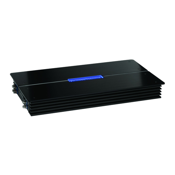
XTA 1000D XTA 1500D XTA 2250D XTREME SERIES CLASS D AMPLIFIER Owners Manual Please read through this manual to familiarize yourself with your new amplifier. Should your PowerBass Xtreme mobile amplifier ever require service, you will need to have the original dated receipt. - Page 3 AMPLIFIERS Thank you and Congratulations Thank you for your decision to purchase a PowerBass Xtreme mobile amplifier! Our PowerBass Xtreme am- plifiers are the result of extensive engineering, testing, and bullet proof construction. They feature the latest in D Class microprocessor technology. Their versatility enables compatibility with optional signal and audio processors.
-
Page 4: Technical Features
Installation of PowerBass mobile amplifiers requires detailed knowledge of electronics wiring and proper speaker impedance. We strongly recommend installation by an authorized PowerBass Xtreme dealer. This Owners Manual only provides general installation and operation instructions. If you have any reservations about your installation skills, please contact your local PowerBass dealer for assistance. -
Page 5: Mounting The Amplifier
MOUNTING LOCATION Your PowerBass Xtreme D Class amplifier comes with mounting feet that may need to be attached to the am- plifier prior to installation. Once the feet are in place, use the amplifier as a template and mark the four screw locations. - Page 6 The amplifier should be protected from exposure to moisture and direct sunlight. The best places to mount your amplifier are: The floor of the trunk, under the driver’s seat, or on the back of the rear seat. For alternate installation locations, please consult your dealer. *** WARNING *** •...
-
Page 7: Control Panel Layout
CONTROL PANEL LAYOUT LINE OUT LINE IN MASTER SLAVE GAIN SUBSONIC BASS EQ PHASE 1 5HZ 50HZ 1 8dB 50Hz 250Hz 0˚ 1 80˚ REMOTE SPEAKER OUTPUT BATT+ FUSE POWER STATUS DO NOT BRIDGE POWER XTA1 500D Fig.2 Panel Layout 1. -
Page 8: Speaker Output Terminals
SLAVE amplifier will be disabled. Only the amplifier you select as MASTER will control these functions. Dual Link Power Doubling Circuit increases the output power as follows: XTA 1000D x 2 = 2,000 watts RMS (2 ohms min) XTA 1500D x 2 = 3,000 watts RMS (2 ohms min) XTA 2250D x 2 = 4,500 watts RMS (2 ohms min) 10. - Page 9 15. REM (Remote Input Terminal) All Powerbass Xtreme amplifiers can be turned on by applying 12 volts to this terminal. This can be found a the rear of the source unit (usually the blue with white stripe wire). If there is not a remote turn on lead the power antenna lead (usually blue) can be used in its place.
-
Page 10: Wiring And Connections
Your PowerBass Xtreme Class D amp will draw large levels of current, so use the largest gauge power/ ground cable possible. Do not “starve” your amplifier by using small power cable. Using under sized power cable can result in unnecessary over-heating of the amplifier, distortion at high volume levels and may even cause the thermal protection circuitry to shut off the amplifier. - Page 11 The gauge of the power and ground cables must be capable of handling the current needed by the entire system. Power and ground cables must be of the same gauge. If the alternator is not capable of supplying enough power for both the vehicle AND the audio system, a high output alternator should be installed for best performance.
- Page 12 Now it’s time to connect the power and ground cables to the amplifier. Cut both cables to length. Strip off 3/4 inch (20mm) of the insulation so that the bare wire fits all the way in the terminal block on the side panel of the amplifier, seating it firmly so no bare wire is exposed.
-
Page 13: Rca Interconnect Wiring
RCA INTERCONNECT WIRING Choose the correct length and style of RCA interconnects for your needs. Always use high quality RCA audio cables (not supplied) for signal connections—those with multiple layers of shielding or a twisted pair variety for better noise rejection. Most trunk/hatchback installations will require a 15-20 foot (4.5 meter) RCA cable, while pickup trucks will require a 6-12 foot (2 meter) RCA cable. -
Page 14: Input Gain Adjustment
Remote Gain Controller Connection Fig.5 Connection with RJ12 Jack Your PowerBass Xtreme D Class amp includes a remote GAIN control module. It uses standard 6-pin telephone wire and modular (U.S.A. style) telephone connectors. To connect the remote GAIN Control to the amplifier, simply insert one end of the telephone plug into the REMOTE GAIN port. -
Page 15: Phase Adjustment
BASS EQ 18dB Fig.7 Bass EQ Control Bass EQ Adjustment This special feature is designed to provide you boost at 45Hz, and it allows you to boost the real Bass EQ up to +18dB. Keep in mind that more is not always better. Setting the control (fig. 7) to the max (18dB) will stress the amplifier and the speakers and could result in damage. -
Page 16: Speaker Wiring
Speaker Load Keep in mind your PowerBass Xtreme D Class amp is a high power amplifier and not a high current amplifier. In other words it requires a minimum impedance of 1 ohm. Both speaker outputs are internally paralleled, thus a minimum speaker impedance of 2 ohms is required when using more then one of the speaker outputs. - Page 17 Too low of an impedance could send your amplifier into protection mode and/or permanently damage the amplifier. At the amplifier end, insert the stripped (bare) speaker wires into the properly marked terminals. Use a Philips (cross) screwdriver to loosen the speaker terminals on the amplifier. Make certain that no bare wire ends touch each other.
- Page 18 3. ONE DUAL VOICE COIL SUBWOOFER SPEAKER (Note: Don’t connect speaker impedance under 2 ohms) SPEAKER OUTPUT BATT+ FUSE POWER STATUS DO NOT BRIDGE POWER XTA1 500D Fig.13 One Subwoofer (2-4 Ohm) with Dual Voice Coil 4. THREE DUAL VOICE COIL SUBWOOFER SPEAKERS (Note: Don’t connect speaker impedance under 1 ohm) SPEAKER OUTPUT BATT+...
- Page 19 5. FOUR SINGLE VOICE COIL SUBWOOFER SPEAKERS (Note: Don’t connect speaker impedance under 1 ohm) SPEAKER OUTPUT BATT+ FUSE POWER STATUS DO NOT BRIDGE POWER XTA1 500D Fig.15 Four Single Voice Coil Subwoofers (1-4 Ohm) NOTE: It is important that a 1-ohm minimum total speaker impedance load is observed! If a impedance load of less than the 1-ohm minimum is used, you will eventually damage your amplifier and void your warranty! For additional wiring suggestions visit our website www.powerbassusa.com...
- Page 20 Wiring for Dual Link/Strapping Two Amplifiers Connect an RCA cable from the head unit or other signal source to the LINE IN on the MASTER amplifier. Connect single channel RCA cable from the MASTER OUTPUT RCA jack to the corresponding RCA jack on the SLAVE amplifier as shown below (fig.16).
- Page 21 You must follow the above diagrams carefully when attempting to wire two of the same model PowerBass Xtreme Class D amplifiers together. Make sure the MASTER and SLAVE switches are properly selected on each amplifier as shown (see #6). Failure to do so will result in damage to the system.
-
Page 22: Reconnect Battery
(or both) speaker wires may be disconnected. Protection Indicator All PowerBass Xtreme amplifiers incorporate self diagnostic Multi-Protection circuitry. This four- way system protects against Impedance Overload, Speaker Short Circuit, Thermal Overheating, and DC Output. The RED L.E.D. provides a visual indication that a problem exists and the protec- tion circuitry has protected the amplifier by shutting down. -
Page 23: Recommended Wire Sizes
RECOMMENDED WIRE SIZES Power Cable Selection Chart Fuse Total 4-7Ft 7-10Ft 10-13Ft 13-16 Ft 16-19 Ft 19-22 Ft In Amperes Length of Wire/Gauge 150A - 200A 2 GA 2 GA 2 GA *1/0* *1/0* *1/0* *1/0* 125A - 150A 4 GA 4 GA 4 GA 4 GA... -
Page 24: Troubleshooting Tips
TROUBLESHOOTING TIPS Problem Solution Power LED not ON With a Volt Ohm Meter (VOM) check: • +12 Volt power terminal (should read +12 to +16VDC • Remote turn-on terminal (should read +12 to +16VDC) • Ground Terminal Power LED lights GREEN, no output •... - Page 25 SPECIFICATIONS FOR XTA D Class Amplifiers POWERBASS XTREME D XTA 1000D XTA 1500D XTA 2250 CLASS MODELS Power Output @ 14.4 VDC Input • 4 Ohms RMS at THD 0.5% 425W 450W 565W • 2 Ohms RMS at THD 0.5%...
- Page 27 POWERBASS ELECTRONICS LIMITED WARRANTY POLICY PowerBass USA, Inc. offers limited warranty on PowerBass products under normal use on the following terms: PowerBass Xtreme Amplifiers are to be free of defects in material and workmanship for a period of one (1) year.
- Page 28 PowerBass Xtreme – A division of PowerBass USA, Inc. 13936 Mountain Avenue – Chino, CA 91710 Tel. (909) 993-5399 – Fax (909) 993-5393 www.powerbassusa.com...
Need help?
Do you have a question about the XTA 1000D and is the answer not in the manual?
Questions and answers