Table of Contents
Advertisement
Quick Links
Advertisement
Table of Contents

Subscribe to Our Youtube Channel
Related Manuals for PowerBass XTA 2160


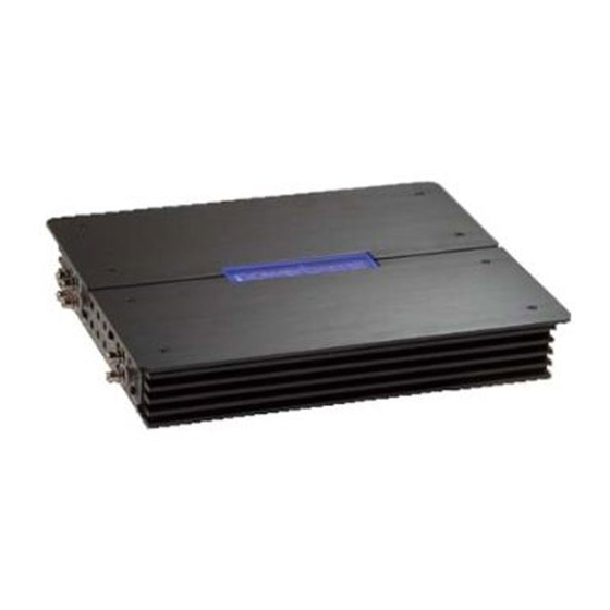
Summary of Contents for PowerBass XTA 2160
-
Page 1: Owners Manual
XTA 2240 XTA 4140 XTREME SERIES A/B CLASS AMPLIFIER Owners Manual Please read through this manual to familiarize yourself with your new amplifier. Should your PowerBass Xtreme mobile amplifier ever require service, you will need to have the original dated receipt. - Page 3 In the interest of safety, PowerBass USA highly recommends listening at lower volume levels when driving.
-
Page 4: Technical Features
Blue Power-on Edge-lit PowerBass Logo INSTALLATION EXPERIENCE Installation of PowerBass mobile amplifiers requires detailed knowledge of electronics wiring and proper speaker impedance. We strongly recommend installation by an authorized PowerBass Xtreme dealer. This Owners Manual only provides general installation and operation instructions. If you have any reservations about your installation skills, please contact your local PowerBass dealer for assistance. -
Page 5: Mounting The Amplifier
MOUNTING LOCATION Your PowerBass Xtreme amplifier comes with mounting feet that may need to be attached to the amplifier prior to installation. Once the feet are in place, use the amplifier as a template and mark the four screw locations. - Page 6 The amplifier should be protected from exposure to moisture and direct sunlight. The best places to mount your amplifier are: The floor of the trunk, under the driver’s seat, or on the back of the rear seat. For alternate installation locations, please consult your dealer. *** WARNING *** •...
-
Page 7: Control Panel Layout
CONTROL PANEL LAYOUT LINE OUT LINE IN GAIN BASS EQ X-OVER 40Hz 500Hz 1 8dB 80Hz 1 .5kHz FULL BRIDGED FUSE BATT+ POWER STATUS POWER SPEAKER OUTPUT XTA2160 LINE IN CH 1 /2 LINE OUT FRONT REAR X-OVER GAIN BASS EQ INPUT 1 8dB 80Hz... - Page 8 10. REM (Remote Input Terminal) All PowerBass Xtreme amplifiers can be turned on by applying 12 volts to this terminal. This can be found on the rear of the source unit in the form of an electric antenna output, or a remote output. If this is not available you can wire to the ACC position on the key (this is a signal that is present when the key is on, but not while starting).
-
Page 9: Wiring And Connections
Your PowerBass Xtreme amplifier requires unrestricted current to deliver peak performance, so don’t “starve” your amplifier by using small power cable. Using too small of power cable can result in unnecessary over- heating of the amplifier, and wire, distortion at high volume levels, thermal protection circuitry to shut-off the amplifier, and may lead to fire. - Page 10 First, check the voltage at the battery with the ignition in the OFF position. The voltmeter should read no less than 12V. If your vehicles electrical system is not up to these specifications, we recommend having it checked by an auto electrician before any further installation. Once the vehicle is checked, make certain the correct cable size is used.
- Page 11 REM (Remote) This terminal must be connected to a switched +12V source. Typically, remote turn-on leads are provided at the source unit that will turn on and off the amplifier in correspondence with the source. If the source unit does not have a remote turn-on lead, then a power antenna wire can be used.
-
Page 12: Rca Interconnect Wiring
If RCA interconnects must cross power cables, noise can best be avoided by crossing them between 45° and 75°. LINE OUT LINE IN GAIN BASS EQ X-OVER 40Hz 500Hz 1 8dB 80Hz 1 .5kHz FULL XTA 2160 XTA 2140 OUTPUTS CAR RADIO/ SOURCE Fig.4 Typical 2-channel amplifier low level input using RCA... -
Page 13: Speaker Load
SPEAKER WIRING AND CONFIGURATIONS Speaker Load Keep in mind your PowerBass Autosound amplifier is a high power amplifier and not a high current amplifier. In other words this amplifier requires a minimum impedance of 2 ohms STEREO and 4 ohms bridged MONO to operate trouble free. - Page 14 Maintaining proper impedance is critical when wiring the Class AB model amplifiers. Improper wiring can cause severe damage to BOTH the woofer and the amplifier. Detailed wiring diagrams are supplied with all PowerBass woofers. IF YOU ARE NOT EXPERIENCED OR UNCOMFORTABLE READING THE WIRING DIAGRAMS CONSULT YOUR AUTHORIZED POWERBASS DEALER BEFORE YOU ATTEMPT TO WIRE THE SYSTEM.
- Page 15 Speaker Output Connections (XA 4140) 4 –CHANNEL SPEAKER OUTPUT CONNECTION (Note: Don’t connect speaker impedance under 2 ohms) 2 ohm minimum 2 ohm minimum FUSE BRIDGED BRIDGED BATT+ POWER STATUS SPEAKER OUTPUT POWER XTA 41 40 2 ohm minimum 2 ohm minimum Fig.7 4-CH Speaker Connection / 2 ohm minimum 3-CHANNEL STEREO/MONO SPEAKER OUTPUT CONNECTION 2 ohm minimum...
- Page 16 5. 2-CHANNEL (BRIDGED MODE) SPEAKER OUTPUT CONNECTION 4 ohm minimum FUSE BRIDGED BRIDGED BATT+ POWER STATUS SPEAKER OUTPUT POWER XTA 41 40 4 ohm minimum Fig.9 2-CH Speaker Connection / 4 ohm minimum...
-
Page 17: Input Gain Adjustment
ADJUSTMENTS AND SETTINGS Input Gain Adjustment GAIN Fig.10 GAIN Control This control (fig. 10) allows you to match the input level of the amplifier to the output level of your head unit. Matching the input can be accomplished in three simple steps: 1. - Page 18 40Hz 500Hz Fig.13 Low Pass Control Low Pass Filter (LPF) Adjustment Using this volume, adjust the LPF frequency for your subwoofer speaker(s) operation. The switch position of X-Over should be at “LPF” INPUT MODE Fig.14 2 - 4 Channel Input Mode Input Mode Switch (XTA 4140 ONLY) Matches the input from the Source Unit to that of the amplifier, either 2 or 4 Channel (See page 13).
-
Page 19: Recommended Wire Sizes
Miscellaneous: ______________________________________________________ This manual is the exclusive property of PowerBass USA, Inc. Any reproduction of this manual, or use other than its intentions is strictly prohibited without the express consent of PowerBass USA, Inc. © Copyright 2009 PowerBass USA, Inc. -
Page 20: Troubleshooting Tips
NOTE: If the Status L.E.D. is activated and glows RED with no speakers connected to the amplifier, and all the power connections are correct, this would indicate an internal problem with the ampli- fier. Contact PowerBass USA or your local dealer. - Page 21 SPECIFICATIONS FOR XTA AB Class Amplifiers POWERBASS XTREME AB CLASS MODELS XTA 2160 XTA 2240 XTA 4140 Power Output @ 14.4 VDC Input • 4 Ohms RMS at 1KHz 100W x 2 130W x 2 75W x 4 • 4 Ohms Bridged RMS...
- Page 23 Please call (909) 993-5399 for PowerBass Customer Service. You must obtain an RA# (Return Authorization Num- ber) to return any product to PowerBass. The RA number must be prominently marked on the outside of the shipping carton or the delivery will be refused. Please pack your return carefully; we are not responsible for items damaged in shipping.
- Page 24 PowerBass Xtreme – A division of PowerBass USA, Inc. 13936 Mountain Avenue – Chino, CA 91710 Tel. (909) 993-5399 – Fax (909) 993-5393 www.powerbassusa.com...
Need help?
Do you have a question about the XTA 2160 and is the answer not in the manual?
Questions and answers