Brocade Communications Systems 7800 Hardware Reference Manual
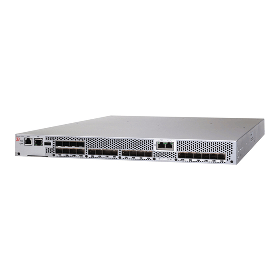
Brocade 7800 extension switch
Hide thumbs
Also See for 7800:
- Hardware installation manual (62 pages) ,
- Quick start manual (2 pages) ,
- Reference manual (370 pages)

Related Manuals for Brocade Communications Systems 7800


Summary of Contents for Brocade Communications Systems 7800
- Page 1 53-1001350-04 ® 31 May 2012 Brocade 7800 Extension Switch Hardware Reference Manual...
- Page 2 Export of technical data contained in this document may require an export license from the United States government. The authors and Brocade Communications Systems, Inc. shall have no liability or responsibility to any person or entity with respect to any loss, cost, liability, or damages arising from the information contained in this book or the computer programs that accompany it.
-
Page 3: Table Of Contents
Brocade 7800 Features ....... . 2 Port side of the Brocade 7800....... 4 Nonport side of the Brocade 7800 . - Page 4 In this appendix ......... . 29 Brocade 7800 components ....... . 29 Weight and physical dimensions .
- Page 5 Regulatory certifications ....... 40 Index Brocade 7800 Extension Switch Hardware Reference Manual 53-1001350-04...
- Page 6 Brocade 7800 Extension Switch Hardware Reference Manual 53-1001350-04...
-
Page 7: About This Document
How this document is organized This document is organized to help you find the information that you need as quickly and easily as possible. The document begins with an introduction to the Brocade 7800 and proceeds through installation and operation procedures. -
Page 8: What's New In This Document
Repeat the previous element, for example “member[;member...]” value Fixed values following arguments are printed in plain font. For example, show WWN Boolean. Elements are exclusive. Example: show mode egress | ingress viii Brocade 7800 Extension Switch Hardware Reference Manual 53-1001350-04... -
Page 9: Command Examples
For definitions of SAN-specific terms, visit the Storage Networking Industry Association online dictionary http://www.snia.org/education/dictionary Notice to the reader This document may contain references to the trademarks of the following corporations. These trademarks are the properties of their respective companies and corporations. Brocade 7800 Extension Switch Hardware Reference Manual 53-1001350-04... -
Page 10: Additional Information
Fibre Channel, storage management, and other applications: http://www.t11.org For information about the Fibre Channel industry, visit the Fibre Channel Industry Association Web site: http://www.fibrechannel.org Optional Brocade Features Optional Brocade features include: Brocade 7800 Extension Switch Hardware Reference Manual 53-1001350-04... -
Page 11: Getting Technical Help
Enables IBM host-based management programs to manage FICON fabric switches in-band by sending commands to the Fabric OS emulated control device. Getting technical help Contact your Brocade 7800 support supplier for hardware, firmware, and software support, including product repairs and part ordering. To expedite your call, have the following information available: 1. -
Page 12: Document Feedback
2. Brocade 7800 Serial Number The Brocade 7800 serial number and corresponding bar code are provided on the serial number label, as illustrated below.: *FT00X0054E9* FT00X0054E9 The serial number label is located as follows: • Brocade 200E—On the nonport side of the chassis •... -
Page 13: Introducing The Brocade 7800 Extension Switch
5 Overview of Brocade 7800 Extension Switch The Brocade 7800 Extension Switch is intended as a platform for Fibre Channel over IP (FCIP). This enables transmission of Fibre Channel data over long distances via IP networks by wrapping Fibre Channel frames in IP packets. -
Page 14: Brocade 7800 Features
Brocade 7800 Features The following table compares features supported on the base and fully upgraded Brocade 7800. It also shows optionally licensed features. TABLE 1 Feature comparison - base 7800 and with the Upgrade License Feature Base 7800 with Upgrade... - Page 15 Before the installation of the Upgrade License, ports beyond the basic four FC and two GbE are shown as Disabled with the switchShow command. • On the base 7800, the two SFP ports (ge0 and ge1) can be configured for use with either copper or optical cables. •...
-
Page 16: Port Side Of The Brocade 7800
GbE ports ge0 through ge5 - (SFP - optical or copper) You can have two trunking groups on a fully licensed Brocade 7800. Groups 1 would consist of FC ports 0-7 and group 2 would be ports 8-15. Brocade 7800 Extension Switch Hardware Reference Manual... -
Page 17: Nonport Side Of The Brocade 7800
12 FRU handle Brocade 7800 management You can use the management functions built into the Brocade 7800 to monitor the fabric topology, port status, physical status, and other information to help you analyze switch performance and to accelerate system debugging. - Page 18 Introducing the Brocade 7800 Extension Switch You can manage the Brocade 7800 using any of the management options listed in Table TABLE 2 Management options for the Brocade 7800 Management Tool Out-of-band Support In-band Support Command line interface (CLI) Ethernet (preferred) or...
-
Page 19: Installing And Configuring The Brocade 7800
“Power supply specifications” on page 30. To ensure adequate cooling, install the Brocade 7800 with the nonport side, which contains the air intake vents, facing a cool-air aisle. Verify that the ambient air temperature does not exceed 400 C (104 F) and that the ambient humidity remains between 20% and 85% while the Brocade 7800 is operating. -
Page 20: Items Included With The Brocade 7800 Extension Switch
Ensure that airflow and temperature requirements are met on an ongoing basis, particularly if the Brocade 7800 is installed in a closed or multirack assembly. • Verify that the additional weight of the Brocade 7800 does not exceed the cabinet’s weight limits or unbalance the cabinet in any way. •... -
Page 21: Setting Up The Brocade 7800 Extension Switch As A Standalone
1. Unpack the Brocade 7800 and verify that all ordered items are present. 2. Clean the four corner depressions on the bottom of the Brocade 7800 and place a rubber foot in each one. This helps prevent the Brocade 7800 from accidentally sliding off the supporting surface. -
Page 22: Providing Power To The Switch
Power is supplied to the switch as soon as the first power supply is connected and turned on. 3. After POST is complete, verify that the Brocade 7800 power and status LEDs on the left of the port side of the switch are green. -
Page 23: Connecting To The Brocade 7800 Using The Serial Connection
1. Remove the plug from the console (serial) port and insert the serial cable provided with the Brocade 7800. 2. Connect the serial cable to the console port on the Brocade 7800 and to an RS232 serial port on the workstation. If the serial port on the workstation is RJ45 instead of RS232, you can remove the adapter on the end of the serial cable and insert the exposed RJ45 connector into the RJ45 serial port on the workstation. -
Page 24: Setting The Switch Ip Address
/dev/ttya -9600 Setting the switch IP address You can configure the Brocade 7800 with a static IP address, or you can use a DHCP (Dynamic Host Configuration Protocol) server to set the IP address of the switch. DHCP is enabled by default. -
Page 25: Changing The Switch Name And Chassis Name
2. Connect an Ethernet cable to the switch Ethernet port and to the workstation or to an Ethernet network containing the workstation. NOTE At this point, the Brocade 7800 can be accessed remotely, by command line or by Web Tools. Ensure that the switch is not being modified from any other connections during the remaining tasks. -
Page 26: Setting The Brocade 7800 Date And Time
You can synchronize the local time of the principal or primary fabric configuration server (FCS) switch to that of an external Network Time Protocol (NTP) server. Perform the following steps to set the date and time of a Brocade 7800. 1. Log in to the switch as admin. -
Page 27: Correcting The Time Zone Of A Brocade 7800
Installing and configuring the Brocade 7800 The ipaddr variable represents the IP address of the NTP server that the Brocade 7800 can access. This argument is optional; by default the value is “LOCL”. sw7800:admin> tsclockserver 192.168.126.60 Updating Clock Server configuration...done. -
Page 28: Fcip And Fibre Channel Routing Services Configuration
-10,0 FCIP and Fibre Channel routing services configuration The ports on the Brocade 7800 are initially set to persistently disabled. If you want to enable the FC ports as a standard E_Port or F_port use the portcfgpersistentenable command to enable the ports. -
Page 29: Verifying Correct Operation And Backup The Configuration
“Powering off the Brocade 7800” on page 28. 5. Verify the correct operation of the Brocade 7800 by entering the switchShow command from the workstation. Verifying correct operation and backup the configuration Perform the following steps to verify correct operation and backup with Brocade 7800 configuration. - Page 30 No_Light FCIP sw7800:admin> 4. Verify the correct operation of the Brocade 7800 in the fabric by entering the fabricShow command from the workstation. This command provides general information about the fabric. 5. Back up the switch configuration to an FTP server by entering the configUpload command and following the prompts.
-
Page 31: Recommendations For Cable Management
Leave at least one meter (three feet) of slack for each port cable. This provides room to remove and replace the Brocade 7800, allows for inadvertent movement of the rack, and helps prevent the cables from being bent to less than the minimum bend radius. - Page 32 Installing and configuring the Brocade 7800 Brocade 7800 Extension Switch Hardware Reference Manual 53-1001350-04...
-
Page 33: Operating The Brocade 7800 Extension Switch
The status LEDs may display solid amber or flash during boot, POST, or other diagnostic tests. This is normal; it does not indicate a problem unless the LEDs do not indicate a healthy state after all boot processes and diagnostic tests are complete. Brocade 7800 Extension Switch Hardware Reference Manual 53-1001350-04... -
Page 34: Leds On The Port Side Of The Extension Switch
• One port status LED for each optical GbE port. • Two LEDs for each fixed copper RJ-45 GbE port, one activity/status LED and one fault LED. Brocade 7800 Extension Switch Hardware Reference Manual 53-1001350-04... - Page 35 Operating the Brocade 7800 Extension Switch Figure 4 on page 23 shows the port side of the Brocade 7800 Extension Switch. FIGURE 4 LEDs on port side System Status LED Port 0 Status LED System Power LED 10 Port 4 Status LED...
- Page 36 Verify that the Ethernet cable is connected correctly. Steady green There is a link No action required. Ethernet No light No activity No action required. Status/Activit Flashing green There is link activity (traffic). No action required. Brocade 7800 Extension Switch Hardware Reference Manual 53-1001350-04...
- Page 37 Port is faulty. Reset the switch from the steady amber workstation. If the fault persists, use the other fixed copper port or the optical/copper SFP ports or return the switch for repair Brocade 7800 Extension Switch Hardware Reference Manual 53-1001350-04...
-
Page 38: Leds On The Nonport Side Of The Brocade 7800
Operating the Brocade 7800 Extension Switch LEDs on the nonport side of the Brocade 7800 The nonport side of the Brocade 7800 has the following LEDs: • One power supply LED next to the AC power switch on each fan and power supply assembly. -
Page 39: Interpreting Post Results
Operating the Brocade 7800 Extension Switch Interpreting POST results POST is a system check that is performed each time the Brocade 7800 is powered on, rebooted, or reset, and during which the LEDs flash different colors. Perform the following steps to determine whether POST completed successfully and whether any errors were detected. -
Page 40: Powering Off The Brocade 7800
“LEDs on the nonport side of the Brocade 7800” on page 26). • In DCFM, double click the 7800 switch icon to open Web Tools, then click the Power Status icon. • Enter the psShow command at the command prompt to display power supply status. -
Page 41: Product Specifications
One IEEE-compliant RJ-45 connector on the port side of the Extension Switch for use with a serial console and 10/100 MBps Ethernet. • Switch status and management LEDs: 1 power LED, 1 status LED, 2 Ethernet LEDs, 2 FRU LEDs. Brocade 7800 Extension Switch Hardware Reference Manual 53-1001350-04... -
Page 42: Weight And Physical Dimensions
Width 43.18 cm (17 in.) Weight (with two FRUs, and no SFPs installed) 10.9 kg (24 lb) Facility requirements Table 7 provides the facilities requirements that must be met for the Brocade 7800. TABLE 7 Facility requirements Type Requirements •... -
Page 43: Environmental Requirements
Environmental requirements Table 8 lists the power supply specifications for the Brocade 7800. TABLE 8 Power supply specifications Specification Value Maximum output of one power supply 150 watts System DC power consumption (excluding Idle: 95 W power supply and fan FRUs) -
Page 44: General Specifications
General specifications ATTENTION Never use the power cord packed with your equipment for other products. General specifications Table 10 lists the general specifications for the Brocade 7800. TABLE 10 General specifications Specification Description Configurable port types The GbE ports can be VE_Ports. -
Page 45: Memory Specifications
Short Wavelength (SWL) Long Wavelength (LWL) (microns) 1 Gbps Memory specifications The Brocade 7800 has three types of memory devices: • Main memory (DDR2 SORDIMM SDRAM) - 2 GB • Boot flash - 4 MB Brocade 7800 Extension Switch Hardware Reference Manual... -
Page 46: Fibre Channel Port Specifications
GbE connection share this bandwidth. Serial port specifications The serial port is located on the port side of the Brocade 7800. The switch uses an RJ-45 connector for the serial port. An RJ-45 to DB9 adaptor is also provided with the Brocade 7800. -
Page 47: Post And Boot Specifications
Not supported POST and boot specifications The Brocade 7800 runs POST by default each time it is powered on; it typically requires from 1 to 3 minutes to boot and complete POST. POST can be skipped after subsequent reboots by entering the fastBoot command. For more information about this command, see the Fabric OS Command Reference. -
Page 48: Fcc Warning (Us Only)
This is a Class A product based on the standard of the Voluntary Control Council for Interference by Information Technology Equipment (VCCI). If this equipment is used in a domestic environment, radio disturbance might arise. When such trouble occurs, the user might be required to take corrective actions. Brocade 7800 Extension Switch Hardware Reference Manual 53-1001350-04... -
Page 49: Power Cords (Japan Denan)
Regulatory compliance Power cords (Japan Denan) Brocade 7800 Extension Switch Hardware Reference Manual 53-1001350-04... -
Page 50: China Statement
English translation of above statement This is a Class A product. In a domestic environment this product may cause radio interference, in which case the user may be required to take adequate measures. Brocade 7800 Extension Switch Hardware Reference Manual 53-1001350-04... -
Page 51: Bsmi Statement (Taiwan)
This is a Class A product. In a domestic environment, this product might cause radio interference, and the user might be required to take corrective measures. The standards compliance label on the Brocade 7800 contains the CE mark which indicates that this system conforms to the provisions of the following European Council directives, laws, and standards: •... -
Page 52: Rtc Battery
1st Ed or latest Japan CISPR22 and JEIDA VCCI-A and Statement (Harmonics) European Union EN60950-1 or latest EN55022 and EN55024 TUV-GS, N CE marking Australia, New Zealand EN55022 and CISPR22 C-Tick mark or AS/NZS CISPR22 Brocade 7800 Extension Switch Hardware Reference Manual 53-1001350-04... - Page 53 KCC mark Class A China (PS only) GB4943-2001 and GB17625.1-2003 or CCC logo CCC logo GB9254-1998 or latest latest Taiwan (PS only) CNS 14336(94) or latest CNS 13438(95) or latest BSMI mark BSMI mark Brocade 7800 Extension Switch Hardware Reference Manual 53-1001350-04...
- Page 54 Regulatory compliance Brocade 7800 Extension Switch Hardware Reference Manual 53-1001350-04...
- Page 55 ID items included with the SAN Router electrical safety laser compliance environmental LEDs on the nonport side of the Extension Switch requirements LEDs on the port side of the Extension Switch Brocade 7800 Extension Switch Hardware Reference Manual 53-1001350-04...
- Page 56 XRC acceleration requirements environmental facility RTC battery set the Extension Switch date and time set the Extension Switch domain ID setting IP address using DHCP static IP address setting up as a standalone unit Brocade 7800 Extension Switch Hardware Reference Manual...
Need help?
Do you have a question about the 7800 and is the answer not in the manual?
Questions and answers