Brocade Communications Systems 7840 Extension Switch Hardware Reference Manual
Extension switch
Hide thumbs
Also See for 7840 Extension Switch:
- Hardware installation manual (85 pages) ,
- Quick start manual (2 pages)

Related Manuals for Brocade Communications Systems 7840 Extension Switch


Summary of Contents for Brocade Communications Systems 7840 Extension Switch
- Page 1 53-1003127-02 13 October 2014 Brocade 7840 Extension Switch Hardware Reference Manual...
- Page 2 OpenScript, VCS, VDX, and Vyatta are registered trademarks, and The Effortless Network and the On-Demand Data Center are trademarks of Brocade Communications Systems, Inc., in the United States and in other countries. Other brands and product names mentioned may be trademarks of others.
-
Page 3: Table Of Contents
About This Document........................ 9 Supported software................... 9 What’s new in this document................9 Introducing the Brocade 7840 Extension Switch..............11 Overview of Brocade 7840 Extension Switch..........11 Brocade 7840 software features............11 Brocade 7840 hardware features............12 Brocade 7840 feature licensing............12 Port side of the switch..................13 Nonport side of the switch................14... - Page 4 Canadian requirements.................55 CE Statement....................55 China CC statement..................56 FCC warning (US only)................. 56 Germany....................... 57 KCC statement (Republic of Korea)..............57 VCCI statement.....................57 Cautions and Danger Notices....................59 Cautions......................59 Danger Notices..................... 61 Index............................ 65 Brocade 7840 Extension Switch Hardware Reference Manual 53-1003127-02...
-
Page 5: Preface
Bold and italic text identify command syntax components. Delimiters and operators define groupings of parameters and their logical relationships. Convention Description bold text Identifies command names, keywords, and command options. italic text Identifies a variable. Brocade 7840 Extension Switch Hardware Reference Manual 53-1003127-02... -
Page 6: Notes, Cautions, And Warnings
A Danger statement indicates conditions or situations that can be potentially lethal or extremely hazardous to you. Safety labels are also attached directly to products to warn of these conditions or situations. Brocade 7840 Extension Switch Hardware Reference Manual 53-1003127-02... -
Page 7: Brocade Resources
OEM/Solution Provider for all of your product support needs. ® • OEM/Solution Providers are trained and certified by Brocade to support Brocade products. • Brocade provides backline support for issues that cannot be resolved by the OEM/Solution Provider. Brocade 7840 Extension Switch Hardware Reference Manual 53-1003127-02... -
Page 8: Document Feedback
• By sending your feedback to documentation@brocade.com. Provide the publication title, part number, and as much detail as possible, including the topic heading and page number if applicable, as well as your suggestions for improvement. Brocade 7840 Extension Switch Hardware Reference Manual 53-1003127-02... -
Page 9: About This Document
The following changes have been made since this document was last released: • Added information about the SFPs included with the switch. • Reorganized the table listing the weight specifications of the switch. Brocade 7840 Extension Switch Hardware Reference Manual 53-1003127-02... - Page 10 What’s new in this document Brocade 7840 Extension Switch Hardware Reference Manual 53-1003127-02...
-
Page 11: Introducing The Brocade 7840 Extension Switch
Switch management......................16 Overview of Brocade 7840 Extension Switch The Brocade 7840 Extension Switch is intended as a platform for Fibre Channel over IP (FCIP). This enables transmission of Fibre Channel data over long distances by way of IP networks by wrapping Fibre Channel frames in IP packets. -
Page 12: Brocade 7840 Hardware Features
Product FC Ports Ethernet Ports WAN rate limiting Approximate configuration Application throughput Base configuration 24 16G 16 1/10GbE 5 Gbps 15 Gbps (see note above) Brocade 7840 Extension Switch Hardware Reference Manual 53-1003127-02... -
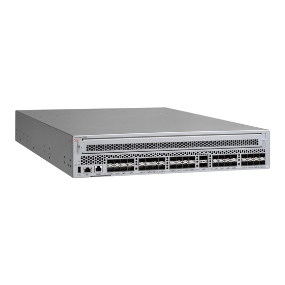
Page 13: Port Side Of The Switch
Port side of the switch The following figures show the port side of the switch. System Status LED Ethernet Management port Power Status LED Console port (RJ-45) USB port Serial number pull-out tab Brocade 7840 Extension Switch Hardware Reference Manual 53-1003127-02... -
Page 14: Nonport Side Of The Switch
40 GbE FCIP ports (QSFP) (2) 1/10 GbE FCIP ports (16) FIGURE 1 Port side view of the Brocade 7840 Extension Switch The Fibre Channel ports are numbered from left to right on the faceplate, as shown in the following figure. - Page 15 The following figure shows the airflow labels on the power supply and fan FRUs. FIGURE 5 Power supply and fan airflow labels 1 Airflow label for PSU integral fan 2 Airflow label for fan FRU Brocade 7840 Extension Switch Hardware Reference Manual 53-1003127-02...
-
Page 16: Switch Management
MIBs, refer to the Fabric OS Administrator's Guide. For release-specific SNMP enhancements, refer to the release notes. NOTE Distribution of standard MIBs has been stopped. Download the required standard MIBs from the www.oidview.com www.mibdepot.com web sites. Brocade 7840 Extension Switch Hardware Reference Manual 53-1003127-02... - Page 17 Out-of-band support In-band support Management Server Ethernet (preferred) or Native in-band console port connection interface (over HBA For information, refer to the Fabric OS Administrator's Guide and only) the Fabric OS Command Reference. Brocade 7840 Extension Switch Hardware Reference Manual 53-1003127-02...
- Page 18 Switch management Brocade 7840 Extension Switch Hardware Reference Manual 53-1003127-02...
-
Page 19: Installing And Configuring The Switch
• Ground all equipment in the rack through a reliable branch circuit connection and maintain ground at all times. Do not rely on a secondary connection to a branch circuit, such as a power strip. Brocade 7840 Extension Switch Hardware Reference Manual 53-1003127-02... -
Page 20: Installation Precautions
Connect the power cord only to a grounded outlet. DANGER Make sure that the power source circuits are properly grounded, then use the power cord supplied with the device to connect it to the power source. Brocade 7840 Extension Switch Hardware Reference Manual 53-1003127-02... -
Page 21: Items Included With The Switch
2. Clean the four corner depressions on the bottom of the Brocade 7840 and place a rubber foot in each one. This helps prevent the Brocade 7840 from accidentally sliding off the supporting surface. 3. Place the Brocade 7840 on a stable, flat surface. Brocade 7840 Extension Switch Hardware Reference Manual 53-1003127-02... -
Page 22: Installing In An Eia Rack
Refer to the documentation that is shipped with the rack-mount kit for installation instructions: • Universal Four-Post Rack Kit Installation Procedure Supporting Brocade 7840 Extension Switch • Universal Two-Post Rack Kit Installation Procedure Supporting the Brocade VDX 6740T and Brocade 7840 Extension Switch. -
Page 23: Providing Power To The Switch
• In a Windows environment: Parameter Value Bits per second 9600 Databits Parity None Stop bits Flow control None • In a UNIX environment using TIP, enter the following string at the prompt: tip /dev/ttyb -9600. Brocade 7840 Extension Switch Hardware Reference Manual 53-1003127-02... -
Page 24: Setting The Switch Ip Address
1. Log in to the switch through Telnet using the admin account. 2. Change the chassis name by using the chassisName command. switch:admin> chassisname my7840chassis 3. Change the switch name by using the switchName command. switch:admin> switchname my7840switch Brocade 7840 Extension Switch Hardware Reference Manual 53-1003127-02... -
Page 25: Creating An Ethernet Connection
Perform the following steps to set the date and time of a switch. 1. Log in to the switch as admin. 2. Enter the date command at the command line using the following syntax: date ["newdate"] Brocade 7840 Extension Switch Hardware Reference Manual 53-1003127-02... -
Page 26: Synchronizing Local Time With An External Source
The parameters listed do not apply if the time zone of the switches has already been changed from the default (8 hours ahead of Pacific Standard Time). For more information about the command parameters, refer to the tsTimeZone command in the Fabric OS Command Reference. Brocade 7840 Extension Switch Hardware Reference Manual 53-1003127-02... -
Page 27: Fcip And Fibre Channel Routing Services Configuration
1. Install the SFP transceivers in the Fibre Channel ports, as required. The ports selected for use in trunking groups must meet specific requirements. For a list of these requirements, refer to the Fabric OS Administrator's Guide. Brocade 7840 Extension Switch Hardware Reference Manual 53-1003127-02... -
Page 28: Verifying Correct Operation And Backing Up The Configuration
This command provides information about switch and port status. sb_70:admin> switchshow switchName: sb_70 switchType: 148.0 switchState: Online switchMode: Native switchRole: Subordinate switchDomain: switchId: fffc46 switchWwn: 10:00:00:05:1e:65:79:04 zoning: ON (PERF_CFG) switchBeacon: FC Router: Brocade 7840 Extension Switch Hardware Reference Manual 53-1003127-02... - Page 29 This command provides general information about the fabric. 5. Back up the switch configuration to an FTP server by entering the configUpload command and following the prompts. sb_70:admin> configupload Protocol (scp, ftp, local) [ftp]: Brocade 7840 Extension Switch Hardware Reference Manual 53-1003127-02...
-
Page 30: Recommendations For Cable Management
A 50-micron cable should not be bent to a radius less than 2 in. under full tensile load and 1.2 in. with no tensile load. Tie wraps are not recommended for optical cables because they are easily overtightened. Brocade 7840 Extension Switch Hardware Reference Manual 53-1003127-02... -
Page 31: Operating The Switch
• One port status LED for each optical 10/40 GbE port FIGURE 7 LEDs on port side 1 System Status LED 6 FC Port 4 Status LED 2 System Power LED 7 40 GbE FCIP Port 0 Status LED Brocade 7840 Extension Switch Hardware Reference Manual 53-1003127-02... - Page 32 2. Reboot the system. NOTE 3. Check the failure Once POST completes indicated on the system and the switch has failed, console steady amber may result. 4. Contact your Extension Switch service provider. Brocade 7840 Extension Switch Hardware Reference Manual 53-1003127-02...
- Page 33 Flickering green Port is online and frames No action required. are flowing through the port. Steady amber Port is receiving light or No action required. signal carrier, but it is not online yet. Brocade 7840 Extension Switch Hardware Reference Manual 53-1003127-02...
-
Page 34: Leds On The Nonport Side Of The Switch
Nonport side of the switch on page 14 for a diagram of the nonport side of the switch. FIGURE 8 LEDs on nonport side 1 Power supply DC status LED 3 Fan status LED Brocade 7840 Extension Switch Hardware Reference Manual 53-1003127-02... - Page 35 • One or more of the fans in the fan assembly has • Replace the faulty fan failed. assembly. Brocade 7840 Extension Switch Hardware Reference Manual 53-1003127-02...
-
Page 36: Interpreting Post Results
Fabric OS Administrator's Guide. NOTE Diagnostic tests may temporarily lock the transmit and receive speed of the links during diagnostic testing. Brocade recommends that you power-cycle the switch after completing offline diagnostics tests. Brocade 7840 Extension Switch Hardware Reference Manual 53-1003127-02... -
Page 37: Field-Replaceable Units
1. Enter the sysShutdown command. This command not only shuts down the key processors but also powers off the switch and all LEDs will go dark. 2. Unplug the AC power cords. Brocade 7840 Extension Switch Hardware Reference Manual 53-1003127-02... -
Page 38: Removing And Replacing Transceivers
The 16 Gbps SFP+ transceivers have an attached pull tab. Instead of using the tool, simply grasp the pull tab and pull straight out to remove the 16 Gbps SFP+ transceiver from the switch. Replacing an SFP+ transceiver Complete the following steps to replace an SFP+ transceiver. Brocade 7840 Extension Switch Hardware Reference Manual 53-1003127-02... - Page 39 Insert the cable into the transceiver until the latching mechanism clicks. Cables are keyed so that they can be inserted in only one way. If a cable does not slide in easily, ensure that it is correctly oriented. Brocade 7840 Extension Switch Hardware Reference Manual 53-1003127-02...
- Page 40 Replacing an SFP+ transceiver Brocade 7840 Extension Switch Hardware Reference Manual 53-1003127-02...
-
Page 41: Removal And Replacement Of Power Supplies And Fans
The power supplies and fan trays are clearly labeled with an orange arrow with an "I." Use the external labels as a guide. Both the PSU and fan FRUs are labeled with the I airflow symbol to indicate that they takes air in. FIGURE 12 Airflow label Brocade 7840 Extension Switch Hardware Reference Manual 53-1003127-02... -
Page 42: Power Supply Removal And Replacement
Airflow Direction : Portside Exhaust (Reverse) Power Supply #2 is OK Airflow Direction : Portside Exhaust (Reverse) DANGER Disconnect the power cord from all power sources to completely remove power from the device. Brocade 7840 Extension Switch Hardware Reference Manual 53-1003127-02... -
Page 43: Time And Items Required
5. Plug the power cord into the power supply to power on the unit. If the power circuit was on before the replacement, the power supply will immediately attempt to power up. Brocade 7840 Extension Switch Hardware Reference Manual 53-1003127-02... -
Page 44: Fan Removal And Replacement
Maintain all three fans in operational condition to provide redundancy. Refer to LEDs on the nonport side of the switch on page 34 for the power supply status LED colors, behaviors, and actions required, if any. Brocade 7840 Extension Switch Hardware Reference Manual 53-1003127-02... -
Page 45: Determining The Need To Replace A Fan
Orient the new fan with the captive screw on the right, as shown below. NOTE Do not force the installation. If the fan does not slide in easily, ensure that it is correctly oriented before continuing. Brocade 7840 Extension Switch Hardware Reference Manual 53-1003127-02... - Page 46 Optionally, if using the command line interface (CLI), enter the fanShow command at the command line prompt to display the status. You can also use the chassisShow command. The fan status can also be viewed using the Web Tools application. Brocade 7840 Extension Switch Hardware Reference Manual 53-1003127-02...
-
Page 47: Brocade 7840 Technical Specifications
Brocade 7840 Technical Specifications The Brocade 7840 Extension Switch provides Fibre Channel, FICON, and FCIP performance for remote replication, backup, and migration. Up to 24 2/4/8/16 Gbps ports Fibre Channel ports, 16 1/10 GbE, and two 40 GbE optical ports support scalable bandwidth, port density, and throughput that extend Storage Area Network (SAN) fabric connectivity over distance. - Page 48 The Brocade 7840 includes all the fans and PSU FRUs, but not the transceivers or cables. Model Height Width Depth Weight Brocade 7840 8.6 cm 44.0 cm 60.9 cm 18.23 kg 3.39 in 17.32 in 24.00 in 40.2 lb Brocade 7840 Extension Switch Hardware Reference Manual 53-1003127-02...
- Page 49 Minimum Notes number of power supplies Brocade 7840 3.90 A 1.98 A 2 x AC 1100 W SR Optics, fans at nominal 388 W 383 W speed, 2PSUs 1524 BTU/hr 1307 BTU/hr Brocade 7840 Extension Switch Hardware Reference Manual 53-1003127-02...
- Page 50 Fibre Channel data transmission range specifications Port speed (Gbps) Cable size Short wavelength Long wavelength Extended long (microns) (SWL) (LWL) wavelength (ELWL) 300 m (984 ft) (OM2) 500 m (1,640 ft) (OM3) Brocade 7840 Extension Switch Hardware Reference Manual 53-1003127-02...
- Page 51 21 m (69 ft) 10 km (6.2 miles) Serial port specifications (pinout RJ-45) Signal Description Not supported Not supported UART1_TXD Transmit data Logic ground Logic ground UART1_RXD Receive data Not supported Not supported Brocade 7840 Extension Switch Hardware Reference Manual 53-1003127-02...
- Page 52 Regulatory compliance (safety) • IEC 60950-1 • CAN/CSA-C22.2 No 60950-1-07, Incl. AM1 • ANSI/UL Std No 60950-1, 2nd, Ed. Incl. AM1 • EN 60950-1 • EK1 - ITB 2000 • ZEK 01.4-08/11.11 Brocade 7840 Extension Switch Hardware Reference Manual 53-1003127-02...
- Page 53 Brocade 7840 Technical Specifications Regulatory compliance (environment) • Refer to the latest revision of the China RoHS document (PN 53-1000428-xx) which ships with the product. Brocade 7840 Extension Switch Hardware Reference Manual 53-1003127-02...
- Page 54 Brocade 7840 Technical Specifications Brocade 7840 Extension Switch Hardware Reference Manual 53-1003127-02...
-
Page 55: Regulatory Statements
The standards compliance label on this device contains the CE mark which indicates that this system conforms to the provisions of the following European Council directives, laws, and standards: • Electromagnetic Compatibility (EMC) Directive 2004/108/EEC • Low Voltage Directive (LVD) 2006/95/EC • EN50082-2/EN55024:1998 (European Immunity Requirements) Brocade 7840 Extension Switch Hardware Reference Manual 53-1003127-02... -
Page 56: China Cc Statement
This equipment has been tested and complies with the limits for a Class A computing device pursuant to Part 15 of the FCC Rules. These limits are designed to provide reasonable protection against harmful interference when the equipment is operated in a commercial environment. Brocade 7840 Extension Switch Hardware Reference Manual 53-1003127-02... -
Page 57: Germany
This is a Class A product based on the standard of the Voluntary Control Council for Interference by Information Technology Equipment (VCCI). If this equipment is used in a domestic environment, radio disturbance might arise. When such trouble occurs, the user might be required to take corrective actions. Brocade 7840 Extension Switch Hardware Reference Manual 53-1003127-02... - Page 58 VCCI statement Brocade 7840 Extension Switch Hardware Reference Manual 53-1003127-02...
-
Page 59: Cautions And Danger Notices
Do not install the device in an environment where the operating ambient temperature might exceed 40°C (104°F). VORSICHT Das Gerät darf nicht in einer Umgebung mit einer Umgebungsbetriebstemperatur von über 40°C (104°F) installiert werden. Brocade 7840 Extension Switch Hardware Reference Manual 53-1003127-02... - Page 60 Spannung, indem Sie mit den elektrischen Kontakten eine geerdete Oberfläche berühren. MISE EN Avant de brancher un câble à un port, assurez-vous de décharger la tension du câble en GARDE reliant les contacts électriques à la terre. Brocade 7840 Extension Switch Hardware Reference Manual 53-1003127-02...
-
Page 61: Danger Notices
Il est possible que le ventilateur tourne encore à grande vitesse PELIGRO Procure no insertar los dedos accidentalmente en la bandeja del ventilador cuando esté desmontando el chasis. El ventilador podría estar girando a gran velocidad. Brocade 7840 Extension Switch Hardware Reference Manual 53-1003127-02... - Page 62 Dangers related to equipment weight DANGER Make sure the rack housing the device is adequately secured to prevent it from becoming unstable or falling over. Brocade 7840 Extension Switch Hardware Reference Manual 53-1003127-02...
- Page 63 Alle Glasfaser-Schnittstellen verwenden Laser der Klasse 1. DANGER Toutes les interfaces en fibres optiques utilisent des lasers de classe 1. PELIGRO Todas las interfaces de fibra óptica utilizan láser de clase 1. Brocade 7840 Extension Switch Hardware Reference Manual 53-1003127-02...
- Page 64 Danger Notices Brocade 7840 Extension Switch Hardware Reference Manual 53-1003127-02...
-
Page 65: Index
LEDs on the nonport side of the Extension Switch determining status LEDs on the port side of the Extension Switch diagnostic tests domain ID nonport side view electrical safety optional features Brocade 7840 Extension Switch Hardware Reference Manual 53-1003127-02... - Page 66 IP address IPv4 IPv6 storage optimized TCP switch IP address static using DHCP synchronize local time with an external source tape pipelining time setting tool, extraction, transceivers transceivers extraction tool replacing Brocade 7840 Extension Switch Hardware Reference Manual 53-1003127-02...
Need help?
Do you have a question about the 7840 Extension Switch and is the answer not in the manual?
Questions and answers