Yamaha RX-497 Owner's Manual
Hide thumbs
Also See for RX-497:
- Owner's manual (326 pages) ,
- Service manual (46 pages) ,
- Owner's manual (56 pages)

Subscribe to Our Youtube Channel
Related Manuals for Yamaha RX-497


Summary of Contents for Yamaha RX-497
- Page 1 RX-497 Stereo Receiver Récepteur stéréo OWNER’S MANUAL MODE D’EMPLOI BEDIENUNGSANLEITUNG BRUKSANVISNING GEBRUIKSAANWIJZING ИНСТРУКЦИЯ ПО ЭКСПЛУАТАЦИИ...
- Page 2 YAMAHA will not be held responsible for any damage resulting from use of this unit with a voltage other than specified.
-
Page 3: Table Of Contents
CONTENTS INTRODUCTION ADVANCED OPERATION FEATURES............. 2 ADVANCED SETUP ..........29 SUPPLIED ACCESSORIES ......... 2 Changing the ADVANCED SETUP menu parameters ............29 CONTROLS AND FUNCTIONS ......3 Switching the remote control ID ......30 Front panel ..............3 ZONE 2 ..............31 Front panel display ............ -
Page 4: Features
FEATURES FEATURES Built-in 2-channel power amplifier Other features ◆ Minimum RMS output power ◆ PURE DIRECT button used to reproduce the purest 75 W + 75 W (8 Ω), 0.04% THD, 20 Hz to 20 kHz source sound ◆ Highly dynamic power, low impedance drive ◆... -
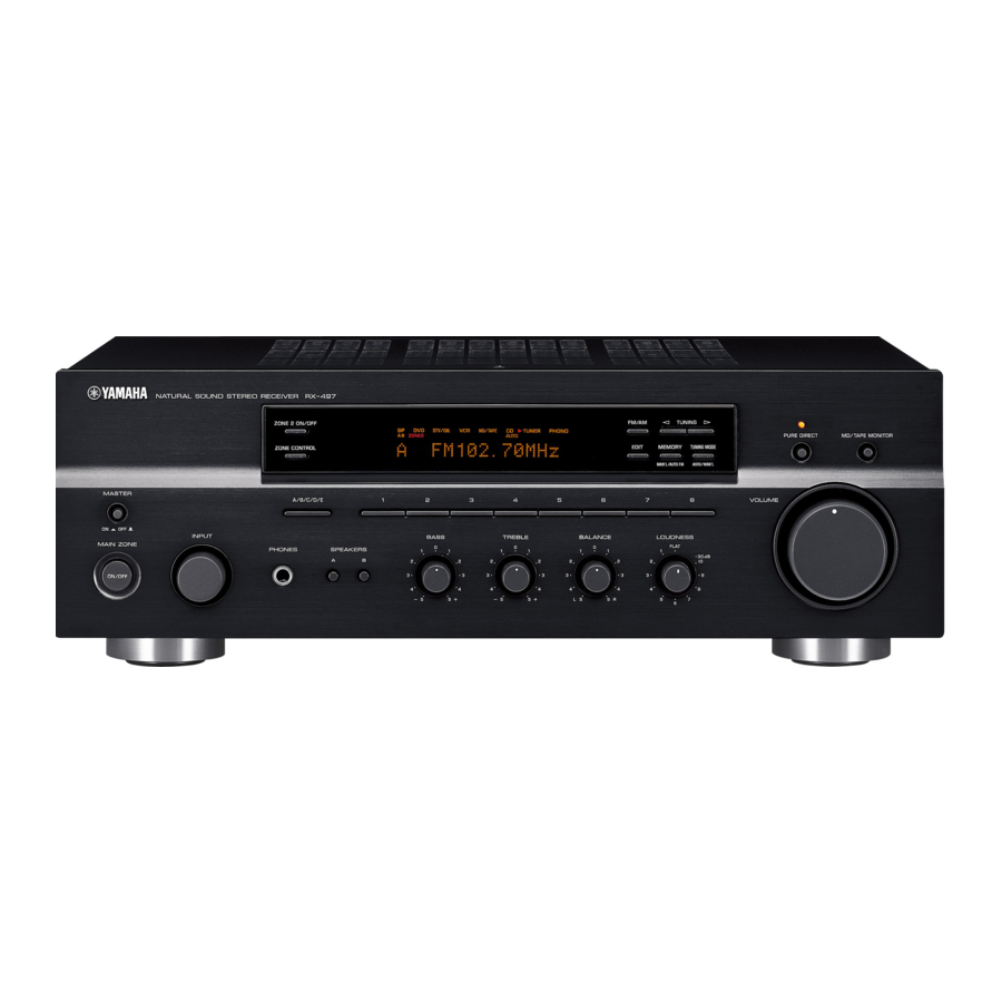
Page 5: Controls And Functions
Switch the remote control ID between ID1 and ID2 when using • In the standby mode, this unit consumes a small amount of multiple YAMAHA receivers or amplifiers (see pages 29, 30). power to receive infrared signals from the remote control. -
Page 6: Input Selector
CONTROLS AND FUNCTIONS 7 EDIT D VOLUME Exchanges the assignment of two preset stations with each Increases or decreases the sound output level. other when TUNER is selected as the input source (see Note page 25). This does not affect the OUT (REC) level. 8 FM/AM E INPUT selector Switches the reception band between AM and FM when... -
Page 7: Front Panel Display
CONTROLS AND FUNCTIONS Front panel display DTV/CBL MD/TAPE TUNER PHONO ZONE2 ZONE3 MD/TAPE MON MEMORY AUTO TUNED STEREO SLEEP MUTE HOLD 1 SP (SPEAKERS) A/B indicators 8 SLEEP indicator Light up according to the set of speakers selected. Lights up when the sleep timer is turned on. Both indicators light up when both sets of speakers are 9 MUTE indicator selected. -
Page 8: Rear Panel
CONTROLS AND FUNCTIONS Rear panel (General model) TUNER VIDEO AUDIO OUTPUT REMOTE VOLTAGE SELECTOR DTV/ DTV/ WOOFER AC OUTLETS SWITCHED (PLAY) 75Ω UNBAL. (REC) SPEAKERS (PLAY) AUDIO IMPEDANCE SELECTOR MONITOR MD/TAPE SET BEFORE POWER ON SELECTEUR D'IMPEDANCE (REC) A OR B: 4ΩMIN. /SPEAKER A + B: 8ΩMIN. -
Page 9: Remote Control
3 Radio Data System control buttons remote control used to control this unit or other Controls the Radio Data System features. components made by YAMAHA or other manufacturers. The functions of the buttons used to control your other Note audio and video components are the same as those of the The Radio Data System features (FREQ/TEXT, EON, PTY corresponding buttons on those components. - Page 10 CONTROLS AND FUNCTIONS Changes the control area (see page 33). 0 SPEAKERS A/B Turns on or off the set of speakers connected to the SPEAKERS A and/or SPEAKERS B terminals on the rear panel of this unit when the corresponding button is pressed each time.
-
Page 11: Installing Batteries In The Remote Control
CONTROLS AND FUNCTIONS Installing batteries in the remote control ■ Notes on batteries • Change all of the batteries if the operation range of the remote control decreases. • Use AA, R6, UM-3 batteries for the remote control. • Make sure that the polarities are correct. See the illustration inside the battery compartment of each remote control. •... -
Page 12: Connections
CONNECTIONS CONNECTIONS CAUTION • Do not connect this unit or other components to the main power until all connections between components are complete. • Do not let the bare speaker wires touch each other or do not let them touch any metal part of this unit. This could damage this unit and/ or the speakers. -
Page 13: Connecting Speakers
CONNECTIONS Connecting speakers ■ Connecting the banana plug Remove approximately 10 mm (3/8 in) of (U.S.A., Canada, Australia and General insulation from the end of each speaker models only) First, tighten the knob and then insert the banana plug into cable and twist the exposed wires of the the end of the corresponding terminal. -
Page 14: Connecting The Am And Fm Antennas
• A properly installed outdoor antenna provides clearer reception than an indoor one. If you experience poor reception quality, an outdoor antenna may improve the quality. Consult your nearest authorized YAMAHA dealer or service center about outdoor antennas. • If you connect an outdoor FM antenna to this unit, do not connect the indoor FM antenna to this unit. -
Page 15: Connecting The Am Loop Antenna
5 to 10 m of vinyl-covered wire to the AM ANT terminal and extend it outdoors from a window. Consult your nearest authorized YAMAHA dealer or service center about outdoor antennas. • The AM loop antenna should always be connected, even if an outdoor AM antenna is connected to this unit. -
Page 16: Connecting The Power Supply Cord
CONNECTIONS Connecting the power supply cord Turning on and off this unit Plug the power supply cord into the AC wall outlet after When all connections are complete, turn on the power of all other connections are complete. this unit. AC power supply cord l TUNING h ZONE 2 ON/OFF... -
Page 17: Playing And Recording
PLAYING AND RECORDING PLAYING AND RECORDING CAUTION Extreme caution should be exercised when you play back CDs encoded in DTS. If you play back a CD encoded in DTS on a DTS-incompatible CD player, you will only hear some unwanted noise that may damage your speakers. -
Page 18: Adjusting The Tonal Quality
PLAYING AND RECORDING ■ Adjusting the LOUDNESS control Adjusting the tonal quality Retains a full tonal range at any volume level, thus compensating for the human ears’ loss of sensitivity to ■ Adjusting the BALANCE control high and low-frequency ranges at a low volume level. Adjusts the sound output balance of the left and right speakers to compensate for sound imbalance caused by CAUTION... -
Page 19: Recording A Source
PLAYING AND RECORDING Recording a source Rotate VOLUME on the front panel (or press VOLUME +/– on the remote control) to adjust the sound output level of the selected source Notes to record from. • The VOLUME, BASS, TREBLE, BALANCE and LOUDNESS controls and the PURE DIRECT buttons have no VOLUME effect on the source being recorded. -
Page 20: Using The Sleep Timer
PLAYING AND RECORDING Using the sleep timer Press SLEEP repeatedly so that SLEEP OFF appears in the front panel display. Use this feature to automatically set this unit to the standby mode after a certain amount of time. The sleep SLEEP timer is useful when you are going to sleep while this unit is playing or recording a source. -
Page 21: Muting The Sound Output
PLAYING AND RECORDING Muting the sound output Press MUTE on the remote control to mute the sound output. The MUTE indicator flashes in the front panel display. MUTE MUTE After a few seconds, MUTE ON disappears from the front panel display. Press MUTE on the remote control again to resume the sound output. -
Page 22: Fm/Am Tuning
FM/AM TUNING FM/AM TUNING There are 2 tuning methods; automatic and manual. Select either method according to your preference and the strength of station signals. Automatic tuning Press TUNING l / h once to begin automatic tuning. Automatic tuning is effective when station signals are Press h to tune into a higher frequency. -
Page 23: Manual Tuning
FM/AM TUNING Manual tuning Press TUNING l / h to manually tune into the desired station. Manual tuning is effective when station signals are weak. Hold down the button to continue tuning search. 2 4 3 l TUNING h ZONE 2 ON/OFF FM/AM l TUNING h PURE DIRECT... -
Page 24: Automatic Preset Tuning
FM/AM TUNING Automatic preset tuning Press FM/AM on the front panel to select FM as the reception band. You can use the automatic preset tuning method to FM appears in the front panel display. automatically store FM stations. This function enables this unit to automatically tune into FM stations with strong FM/AM signals and store up to 40 (8 stations in each of the 5... - Page 25 FM/AM TUNING ■ Customized automatic preset tuning Press TUNING l / h on the front panel to You can specify a preset station group and a preset station number from which this unit stores the FM stations begin automatic preset tuning. received by automatic preset tuning.
-
Page 26: Manual Preset Tuning
FM/AM TUNING Manual preset tuning Press one of the preset station number buttons on the front panel to select a preset You can also manually store up to 40 stations (8 stations in station number (1 to 8) where you want to each of the 5 groups, A1 to E8). -
Page 27: Selecting Preset Stations
FM/AM TUNING Selecting preset stations Exchanging preset stations You can tune into the desired station simply by selecting You can exchange the assignment of two preset stations the preset station number where it is stored. with each other. The following procedure describes an example where a preset station E1 is exchanged with another preset station A5. -
Page 28: Radio Data System (Europe Model Only)
RADIO DATA SYSTEM (EUROPE MODEL ONLY) RADIO DATA SYSTEM (EUROPE MODEL ONLY) Receiving Radio Data System Changing the Radio Data System stations mode Radio Data System is a data transmission system used by FM Four modes are available for displaying Radio Data stations in many countries. -
Page 29: Pty Seek Function
RADIO DATA SYSTEM (EUROPE MODEL ONLY) PTY SEEK function Notes • Do not press FREQ/TEXT until a Radio Data System indicator If you select the desired program type, this unit lights up in the front panel display. You cannot change the mode automatically searches all preset Radio Data System if you press the button prior to this. -
Page 30: Eon Function
RADIO DATA SYSTEM (EUROPE MODEL ONLY) EON function Press PRESET/CH u / d on the remote control to select the desired program type. This function uses the EON data service on the Radio The selected program type appears in the front panel Data System station network. -
Page 31: Advanced Setup
ADVANCED SETUP ADVANCED SETUP ■ ADVANCED SETUP menu parameters Changing the ADVANCED SETUP Change the initial settings (indicated in bold under each parameter) to reflect the needs of your listening menu parameters environment. The ADVANCED SETUP menu is displayed in the front Factory presets PRESET panel display. -
Page 32: Switching The Remote Control Id
When you change the remote control ID, you must switch the remote control ID of this unit (see page 29). When using multiple YAMAHA receivers or amplifiers with the same default code setting, you may unwantedly operate those components simultaneously. -
Page 33: Zone 2
• An amplifier and speakers for the second room Some YAMAHA models are able to connect directly to the REMOTE OUT jack on the rear panel of this unit. If you own these products, you may not need to use an infrared emitter. Up to six YAMAHA components can be connected as shown below. -
Page 34: Controlling Zone 2
ZONE 2 Controlling Zone 2 You can control the input source of Zone 2 independently of the listening conditions in the main room. Press ZONE 2 ON/OFF on the front panel to turn on Zone 2. ZONE 2 ON/OFF Press ZONE 2 CONTROL on the front panel The ZONE 2 indicator flashes in the front panel display. -
Page 35: Remote Control Features
The shaded areas below can be used to control this unit. The shaded areas below can be used to control other audio and video components made by YAMAHA and other manufacturers. Each button has a different function depending on the selected component. Select... -
Page 36: Controlling Other Components
REMOTE CONTROL FEATURES Controlling other components In addition to controlling this unit, you can also control other audio and video components made by YAMAHA TV MUTE TV INPUT MUTE and other manufacturers using the supplied remote STANDBY POWER POWER POWER control. -
Page 37: Setting Remote Control Codes
RETURN DISPLAY PRESET/CH Note You may not be able to operate your other YAMAHA components even if the YAMAHA remote control code is Notes initially set as listed above. In this case, try setting other • If the manufacturer of your component has more than one code, YAMAHA remote control codes. -
Page 38: Troubleshooting
Refer to the chart below if this unit does not function properly. If the problem you are experiencing is not listed below or if the instructions below do not help, set this unit to the standby mode, disconnect the power cord, and contact the nearest authorized YAMAHA dealer or service center. ■ General... - Page 39 TROUBLESHOOTING The power of this unit is turned off, or this Turn on the power of this unit. The sound is unit is set to the standby mode. degraded when listening with the headphones connected to the CD player or the tape deck connected to this unit.
- Page 40 TROUBLESHOOTING ■ Remote control Problem Cause Remedy page Wrong distance or angle. The remote control will function within a maximum The remote control range of 6 m (19.7 ft) and no more than 30 degrees does not work nor off-axis from the front panel. function properly.
-
Page 41: Specifications
SPECIFICATIONS SPECIFICATIONS AUDIO SECTION VIDEO SECTION • Minimum RMS Output Power • Video Signal Type (8 Ω , 20 Hz to 20 kHz, 0.04% THD) ...... 75 W + 75 W [U.S.A., Canada and General models] ........ NTSC [Other models] ............... PAL •...
Need help?
Do you have a question about the RX-497 and is the answer not in the manual?
Questions and answers