Advertisement
OWNER'S MANUAL
Non-Programmable
Digital Thermostat
72
Millivolt Compatible
Battery Operated
Digital Display
TOTALINE
Use with most Air Conditioning & Heating Systems including: 1 Stage
Electric Cooling & Gas Heating, Heat Pump, Electric Heat, Hydronic Heat,
Fan Coils and PTAC units..
Replacement Components Division - Carrier Corporation - Made in China
P/N P474-0130
TOTALINE
DC Voltage Compatible
Stages: 1-Heat, 1-Cool
Easy Operation
Star
Advertisement
Table of Contents

Related Manuals for TOTALINE P474-0130


Summary of Contents for TOTALINE P474-0130
- Page 1 OWNER'S MANUAL P/N P474-0130 Non-Programmable Digital Thermostat TOTALINE Millivolt Compatible DC Voltage Compatible Battery Operated Stages: 1-Heat, 1-Cool Digital Display Easy Operation TOTALINE Star Use with most Air Conditioning & Heating Systems including: 1 Stage Electric Cooling & Gas Heating, Heat Pump, Electric Heat, Hydronic Heat, Fan Coils and PTAC units..
-
Page 2: Table Of Contents
OWNER'S MANUAL DIGITAL THERMOSTAT Contents Page # Safety Warnings Location of Controls Display Normal Operation Preparation Remove Old Thermostat Installation/Battery Replacement Wire Connections Jumper Configuration Test Operation Troubleshooting Warranty Page 2 Page 2... -
Page 3: Safety Warnings
INSTALLATION INSTRUCTIONS Safety Warnings P/N P474-0130 CAUTION Follow Installation Instructions carefully. DISCONNECT POWER TO THE HEATER - AIR CONDITIONER BEFORE REMOVING THE OLD THERMOSTAT AND INSTALLING WARNING THE NEW THERMOSTAT. CAUTION The 2 Alkaline “AA” batteries must be replaced at least every 12 months to assure proper operation. -
Page 4: Location Of Controls
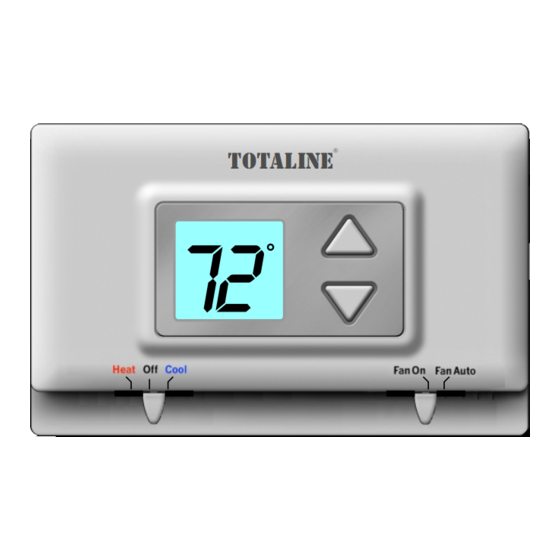
OWNER'S MANUAL DIGITAL THERMOSTAT Location of Controls TEMPERATURE DISPLAY TOTALINE UP & DOWN BUTTONS MODE SWITCH FAN SWITCH Heat, Cool or Off On or Auto Page 4... -
Page 5: Display
OWNER'S MANUAL DIGITAL THERMOSTAT Display 78 74 SET TEMP Current room temperature. If the Up or Down arrow buttons are pressed the thermostat will show the desired Set Temp temperature indicator. Once this screen is reached you may use the Up or Down arrow buttons to adjust the desired room temperature. -
Page 6: Normal Operation
OWNER'S MANUAL DIGITAL THERMOSTAT Normal Operation TOTALINE UP & DOWN BUTTONS MODE SWITCH FAN SWITCH Heat, Cool or Off On or Auto Manual Operation Select Heat or Cool with the mode switch. Normally leave the fan switched to Fan Auto. -
Page 7: Preparation
INSTALLATION INSTRUCTIONS Step #1 Preparation TOTALINE Proper installation of the thermostat will be accomplished by following these step Heat Off Cool Fan On FanA uto by step instructions. If you are unsure about any of these steps, call a qualified technician for assistance. - Page 8 INSTALLATION INSTRUCTIONS Remove & Replace Step #2 Old Thermostat Remove the cover of the old thermostat. TOTALINE If it does not come off easily check for Heat Off Cool Fan On FanA uto screws. TOTALINE Loosen the screws holding the thermostat base or subbase to the wall, and lift away.
-
Page 9: Installation/Battery
INSTALLATION INSTRUCTIONS Installation / Battery Step #3 Replacement Open The New Thermostat The top of the thermostat housing has two (2) screw- driver slots to assist when seperating. SCREWDRIVER SLOTS To pull the housing apart, insert a small blade screw- driver into the slot and rotate 90 . - Page 10 INSTALLATION INSTRUCTIONS Battery Replacement REPLACE WITH ALKALINE BATTERIES AT LEAST ONCE EVERY YEAR, OR WHEN THE “LOW BATTERY” ICON APPEARS (pages 3,9). POSITION BATTERIES AS SHOWN USE “AA” SIZE USE “AA” SIZE ALKALINE BATTERIES ALKALINE BATTERIES FAN W/ HEAT HEAT PUMP Page 10...
-
Page 11: Wire Connections
These drafts, left unchecked, may cause incorrect room temperature readings. Please do not remove this label from the thermostat. Insert the wires MODEL: P474-0130 97061606 4Z95 USE SIZE “AA” through the slots provided in the label MADE IN CHINA ALKALINE BATTERIES as shown in Fig. - Page 12 INSTALLATION INSTRUCTIONS Sample Wiring Diagrams Gas or Electric Heat 4 Wire, 1 Stage Cooling, 1 Stage Gas Heat Residential Gas or Electric Heat *, Electric Cool, split systems & package units 4 Conductor 18 to 22 gauge unshielded cable from the thermostat to the equipment.
- Page 13 INSTALLATION INSTRUCTIONS Sample Wiring Diagrams Gas or Electric Heat 4 Wire, 1 Stage Cooling, 1 Stage Heat-Heat Pump with O reversing valve. Residential Heat Pumps, split systems & package units, with no auxiliary heat. 4 Conductor 18 to 22 gauge unshielded cable from the thermostat to the equipment.
- Page 14 INSTALLATION INSTRUCTIONS Sample Wiring Diagrams Gas or Electric Heat 4 Wire, 1 Stage Cooling, 1 Stage Heat-Heat Pump with B reversing valve. Residential Heat Pumps, split systems & package units, with no auxiliary heat. 4 Conductor 18 to 22 gauge unshielded cable from the thermostat to the equipment.
- Page 15 INSTALLATION INSTRUCTIONS Sample Wiring Diagrams Gas or Electric Heat 3 Wire, 1 Stage Heat Residential Gas or Electric Heat units with a separately controlled fan. 3 Conductor 18 to 22 gauge unshielded cable from the thermostat to the equipment. POWER GAS OR ELECTRIC HEAT Page 15...
- Page 16 INSTALLATION INSTRUCTIONS Sample Wiring Diagrams Gas or Electric Heat 2 Wire, 1 Stage Gas Heat Residential Gas or Millivolt units. 2 Conductor 18 to 22 gauge unshielded cable from the thermostat to the equipment. POWER GAS OR ELECTRIC HEAT Page 16...
- Page 17 INSTALLATION INSTRUCTIONS Sample Wiring Diagrams Gas or Electric Heat 3 Wire, 1 Stage Cooling Residential Electric Cool units 3 Conductor 18 to 22 gauge unshielded cable from the thermostat to the equipment. POWER COOLING Page 17...
-
Page 18: Jumper Configuration
ALKALINE BATTERIES ALKALINE BATTERIES FAN W/ HEAT HEAT PUMP If the HVAC unit has First Stage Electric Heat TOTALINE then jumper should be set to ON. If the Heat Off Cool Fan On FanA uto jumper is set for Fan w/ Heat On, the fan will energize immediately on a call for heating. -
Page 19: Test Operation
INSTALLATION INSTRUCTIONS Step #6 Test Operation Turn on the power to the Heating/Air TOTALINE Conditioning system. Heat Off Cool Fan On FanA uto Adjust the Slide Switch until it is located TOTALINE under the word HEAT on the thermostat. Heat Off Cool... - Page 20 INSTALLATION INSTRUCTIONS Trouble Shooting SYMPTOM: The slide switches on the thermostat TOTALINE are very difficult to move. Heat Off Cool Fan On FanA uto CAUSE: The backplate of the thermostat is deformed by being screwed tightly into a wall that is not perfectly flat.
- Page 21 Mode Switch position (page 10), or replace the batteries. Battery Stat P/N P474-0130 Tested to Comply with FCC Standards FOR HOME OR OFFICE USE 4Z95 P/N 88-396 Rev.
-
Page 22: Warranty
INSTALLATION INSTRUCTIONS Warranty One-Year Warranty - This Product is warranted to be free from defects in material and workmanship. If it appears within one year from the date of original installation, whether or not actual use begins on that date, that the product does not meet this warranty, a new or remanufactured part, at the manufacturer’s sole option, to replace any defective part will be provided without charge for the part itself;...
Need help?
Do you have a question about the P474-0130 and is the answer not in the manual?
Questions and answers