
Subscribe to Our Youtube Channel
Related Manuals for Heat Controller HRE1318/1360-1A


Summary of Contents for Heat Controller HRE1318/1360-1A
- Page 1 Installation and Operation Manual HRE1318/1360-1A Split System Heat Pump Systems...
- Page 2 13 SEER 1 TO 5 TON HEAT PUMPS RECOGNIZE THIS SYMBOL AS AN INDICATION OF IMPORTANT SAFETY INFORMATION! WARNING ▲WARNING THESE INSTRUCTIONS ARE INTENDED AS AN AID TO These instructions are intended as an aid to qualified licensed QUALIFIED, LICENSED SERVICE PERSONNEL FOR PROPER service personnel for proper installation, adjustment and INSTALLATION, ADJUSTMENT AND OPERATION OF THIS UNIT.
-
Page 3: Table Of Contents
TABLE OF CONTENTS 1.0 SAFETY INFORMATION ..........3 2.0 GENERAL INFORMATION . -
Page 4: Safety Information
1.0 SAFETY INFORMATION WARNING Disconnect all power to unit before starting maintenance. Failure to do so can cause electrical shock resulting in severe personal injury or death. WARNING Turn off electric power at the fuse box or service panel before making any electrical connections. -
Page 5: General Information
2.0 GENERAL WARNING The manufacturer’s warranty does not cover any damage or defect to the heat pump caused by the attachment or use of any components. Accessories or devices (other than those authorized by the manufactur- er) into, onto or in conjunction with the heat pump. You should be aware that the use of unauthorized components, accessories or devices may adversely affect the operation of the heat pump and may also endanger life and property. -
Page 6: Dimensions
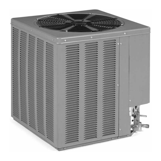
2.3 DIMENSIONS (SEE FIGURE 1) FIGURE 1 AIR DISCHARGE: ALLOW DIMENSIONS 60” MINIMUM CLEARANCE. A-00008 AIR INLETS (LOUVERED PANELS) ALLOW 6” MINIMUM CLEARANCE SERVICE ACCESS ALLOW 24” CLEARANCE SEE DETAIL A 2" BASE PAN (BOTTOM VIEW) DO NOT OBSTRUCT DRAIN HOLES DIMENSIONAL DATA (SHADED). -
Page 7: Electrical And Physical Data
2.4 ELECTRICAL & PHYSICAL DATA (SEE TABLE 1) TABLE 1 ELECTRICAL AND PHYSICAL DATA ELECTRICAL DATA PHYSICAL DATA 13 SEER Fuse or HACR Compressor Outdoor Coil Weight Fan Motor Minimum R-22 ➁ Phase Cooling Circuit Breaker Full Load Circuit Face Area Rated Load Locked Rotor Frequency (Hz) -
Page 8: Heat Pump Location
3.2 HEAT PUMP LOCATION Consult local and national building codes and ordinances for special installation requirements. Following location information will provide longer life and simplified servicing of the outdoor heat pump. NOTE: These units must be installed outdoors. No ductwork can be attached, or other modifications made, to the discharge grille. -
Page 9: Unit Mounting
FIGURE 2 RECOMMENDED ELEVATED INSTALLATION 3.6 UNIT MOUNTING If elevating the heat pump, either on a flat roof or on a slab, observe the following guidelines. • The base pan provided elevates the heat pump 2” above the base pad. •... -
Page 10: Refrigerant Connections
FIGURE 3 TIE-DOWN KIT ASSEMBLY DETAIL A STEP 5: Gauge the amount of washers needed by stacking washers and metal strap in place, as shown in Figure 3, Detail A. Typical installation requires 6 to 7 wash- ers. STEP 6: Insert concrete fastener into hole in metal strap, insert washers over end of fas- tener, and then insert into hole drilled into concrete. -
Page 11: Location
6.1 LOCATION Do not install the indoor coil in the return duct system of a gas or oil furnace. Provide a service inlet to the coil for inspection and cleaning. Keep the coil pitched toward the drain connection. CAUTION When coil is installed over a finished ceiling and/or living area, it is recommended that a secondary sheet metal condensate pan be constructed and installed under entire unit. -
Page 12: Tubing Installation
7.5 TUBING INSTALLATION Observe the following when installing correctly sized type “L” refrigerant tubing between the condensing unit and evaporator coil: • If a portion of the liquid line passes through a hot area where liquid refrigerant can be heated to form vapor, insulating the liquid line is required. •... -
Page 13: Leak Testing
TABLE 2 SUCTION LINE LENGTH AND CAPACITY MULTIPLIER 13 SEER Cooling Capacity Suction Line 3/4” I.D. Sweat 7/8” I.D. Sweat 7/8” I.D. Sweat (4) Connection Size 5/8” O.D. Optional 3/4” O.D. Optional 7/8” O.D. Optional Suction Line 1-1/8” O.D. Standard 3/4”... - Page 14 TABLE 3 LIQUID LINE SIZE Liquid Line Size Liquid Line Size Liquid Outdoor Unit Above Indoor Coil Outdoor Unit Below Indoor Coil Line Line Size System Total Length—Feet [m] Total Length—Feet [m] Connection Capacity (Inch Size Model O.D.) (Inch I.D.) [7.62] [15.24] [22.86]...
-
Page 15: Demand Defrost Control
8.0 DEMAND DEFROST CONTROL The demand defrost control is a printed circuit board assembly consisting of solid state control devices with electro-mechanical outputs. The demand defrost control monitors the outdoor ambient temperature, outdoor coil temperature, and the com- pressor run-time to determine when a defrost cycle is required. 8.1 DEFROST INITIATION A defrost will be initiated when the three conditions below are satisfied: 1) The outdoor coil temperature is below 35°F. -
Page 16: Test Mode
8.4 TEST MODE The test mode is initiated by shorting the TEST pins. In this mode of operation, the enable temperature is ignored and all timers are sped up by a factor of 240. To initi- ate a manual defrost, short the TEST pins. Remove the short when the system switches to defrost mode. -
Page 17: Start Up & Performance
10.0 START UP AND PERFORMANCE Even though the unit is factory charged with Refrigerant-22, the charge must be checked to the charge table attached to the service panel and adjusted, if required. (See Table 1). Allow a minimum of 5 minutes running. Before analyzing charge, see the instructions on the unit service panel rating plate for marking the total charge. -
Page 18: Charging By Weight
12.2 CHARGING BY WEIGHT For a new installation, evacuation of interconnecting tubing and indoor coil is ade- quate; otherwise, evacuate the entire system. Use the factory charge shown in Table 1 of these instructions or unit data plate. Note that charge value includes charge required for 15 ft. -
Page 19: Control Wiring
TABLE 4 VOLTAGE RANGES (60 HZ) Operating Voltage Range at Copeland Nameplate Voltage Maximum Load Design Conditions for Compressors 208/230 (1 Phase) 197 - 253 208/230 (3 Phase) 187 - 253 414 - 506 517 633 13.3 CONTROL WIRING (See Figure 5) If the low voltage control wiring is run in conduit with the power supply, Class I insu- lation is required. -
Page 20: Compressor Crankcase Heat
14.0 FIELD INSTALLED ACCESSORIES 14.1 COMPRESSOR CRANKCASE HEATER (CCH) While scroll compressors usually do not require crankcase heaters, there are instances when a heater should be added. Refrigerant migration during the off cycle can result in a noisy start up. Add a crankcase heater to minimize refrigeration migration, and to help eliminate any start up noise or bearing “wash out.”... -
Page 21: Troubleshooting
16.0 TROUBLE SHOOTING In diagnosing common faults in the heat pump system, develop a logical thought pattern as used by experienced technicians. The charts which follow are not intend- ed to be an answer to all problems but only to guide the technician’s thinking. Through a series of yes and no answers, follow the logical path to a likely conclu- sion. -
Page 22: Cooling Mechanical Checks Flow Chart
16.2 COOLING MECHANICAL CHECKS FLOW CHART Unit Running? Go to Electrical Pressure problems? Checks Flow Chart High Head Pressure Low Head Pressure Low Suction Pressure Dirty Outdoor Coil Low on Charge Dirty Filters Inoperative Outdoor Fan Open IPR Valve Dirty Indoor Coil Overcharge Low Ambient Temperature Inadequate Indoor Air Flow... -
Page 23: Heating Mechanical Checks Flow Chart
16.3 HEATING MECHANICAL CHECKS FLOW CHART Unit Running? Go to Electrical Pressure problems? Checks Flow Chart High Head Pressure Low Head Pressure Low Suction Pressure Dirty Filters Low on Charge Dirty Outdoor Coil Dirty Indoor Coil Low Indoor Temperature Inadequate Air Flow Over Outdoor Coil Inoperative Indoor Blower Open IPR Valve... -
Page 24: Defrost Mechanical Checks Flow Chart
16.4 DEFROST MECHANICAL CHECKS FLOW CHART DEFROST SYSTEM No Defrost Incomplete Defrost Excessive Defrost Reversing Valve Stuck Poor Sensor Location Wrong Defrost Control Timer Setting No Defrost Timer Wrong Defrost Control Control Power Timer Setting Poor Sensor Location Failed Defrost Control Failed Defrost Relay Low System Charge (doesn’t stop O.D. -
Page 25: General Troubleshooting Chart
16.5 GENERAL TROUBLE SHOOTING CHART WARNING Disconnect all power to unit before servicing. Contactor may break only one side. Failure to shut off power can cause electrical shock resulting in personal injury or death. SYMPTOM POSSIBLE CAUSE REMEDY Unit will not run •... -
Page 26: Service Analyzer Chart
16.6 SERVICE ANALYZER CHART COMPRESSOR OVERHEATING SYMPTOMS POSSIBLE CAUSE CHECK/REMEDIES High superheat Low charge Check system charge Faulty metering device Restricted cap tube, TEV (TXV) Power element superheat adjustment Foreign matter stopping flow High internal load Hot air (attic) entering return Heat source on;... - Page 27 SYMPTOMS POSSIBLE CAUSE CHECK OR REMEDIES Short cycling of compressor (cont.) Low charge Check system charge Low evaporator air flow Dirty coil Dirty filter Duct too small or restricted Faulty run capacitor Replace Faulty internal overload Replace compressor Faulty Compressor Valves Fast equalization/ Replace compressor and examine Low pressure difference...
- Page 28 LOSS OF LUBRICATION SYMPTOMS POSSIBLE CAUSE CHECK OR REMEDIES Compressor failures Line tubing too long Add oil to the recommended level Line tubing too large Reduce pipe size to improve oil return Low suction pressure Low charge Check system charge Refrigerant leaks Repair and recharge Cold, Noisy compressor - Slugging...
- Page 29 THERMOSTATIC EXPANSION VALVES SYMPTOMS POSSIBLE CAUSE CHECK OR REMEDIES High Superheat, Low Suction Pressure Moisture freezing and blocking valve Recover charge, install filter-drier, evacuate system, recharge Dirt or foreign material blocking valve Recover charge, install filter-drier, evacuate system, recharge Low refrigerant charge Correct the charge Vapor bubbles in liquid line Remove restriction in liquid line...
- Page 30 THERMOSTATIC EXPANSION VALVES SYMPTOMS POSSIBLE CAUSE CHECK OR REMEDIES Superheat is low to normal Unequal evaporator circuit loading Ensure air flow is equally distributed with low suction pressure through evaporator Ensure proper piston is inserted into RCBA or RCHA evaporator coil distributor Check for blocked distributor tubes...
-
Page 31: Wiring Diagrams
17.0 WIRING DIAGRAMS FIGURE 6 WIRING DIAGRAM OPTIONAL: BELLY BAND CRANKCASE HEATER 90-101229-02 01-19-04... - Page 32 Design, specifications, performance data and materials subject to change without notice. 1900 Wellworth Ave., Jackson, Michigan 49203 • Ph. 517-787-2100 • Fax 517-787-9341 www.heatcontroller.com THE QUALITY LEADER IN CONDITIONING AIR 09/06...
Need help?
Do you have a question about the HRE1318/1360-1A and is the answer not in the manual?
Questions and answers