
Related Manuals for Yamaha PZ50FXW


Summary of Contents for Yamaha PZ50FXW
- Page 1 SNOWMOBILE OWNER’S MANUAL PZ50FXW PZ50GTW PZ50MW PZ50VTW LIT-12628-02-60 8GK-28199-10...
- Page 3 Record the frame number, engine number (Primary ID), and key number in the spaces provided for assistance when ordering spare parts from a Yamaha dealer. 1 The frame number is the seventeen-digit number stamped on the frame of the snowmobile. (See fig.
- Page 4 ESU00011 I NTRODUCTION Congratulations on your purchase of a Yamaha snowmo- bile. This model is the result of Yamaha’s vast experience in the production of fine sporting and touring snowmo- biles. It represents the high degree of craftsmanship and reliability that have made Yamaha a leader in these fields.
- Page 5 PLEASE READ AND UNDERSTAND THIS MANUAL COMPLETELY BEFORE OPERATING THE SNOWMO- BILE. NOTE: Yamaha continually seeks advancements in product design and quality. Therefore, while this manual con- tains the most current product information available at the time of printing, there may be minor discrepan- cies between your snowmobile and this manual.
-
Page 6: Table Of Contents
ESU00003 CONTENTS YAMAHA MOTOR CORPORATION, Grip/thumb warmer adjustment U.S.A. SNOWMOBILE LIMITED switch ..........5-11 WARRANTY ........1-1 Passenger grip warmer switch ..5-11 Auxiliary DC jack ......5-12 Shroud latches ......5-12 YAMAHA EXTENDED SERVICE Shroud and covers ......5-13 (Y.E.S.) ..........1-4 Drive guard ........5-14 V-belt holder ........5-14 LOCATION OF THE IMPORTANT Backrest ........5-15... - Page 7 To start out and accelerate....7-3 Replacing a headlight bulb ....8-33 Braking ..........7-3 Adjusting the headlight beams ..8-34 Turning ..........7-4 Battery ...........8-34 Riding uphill ........7-4 Replacing a fuse......8-35 Riding downhill ........7-5 Traversing a slope ......7-5 TROUBLESHOOTING .......9-1 Ice or icy surface ......7-5 Hard-packed snow......7-6 STORAGE ........10-1 Operation on surfaces other than...
-
Page 8: Yamaha Motor Corporation, U.s.a. Snowmobile Limited Warranty
WARRANTY PERIOD: WARRANTY TRANSFER: To transfer any remain- 1. All Yamaha snowmobiles shall be warranted for a ing warranty from the original purchaser to any subse- term of one (1) year from the date of purchase, plus quent purchaser, it is imperative that the machine be a special early-season extension (if applicable). - Page 9 Post Office Box 6555 specified in the Owner’s Manual? Cypress, California 90630 A. No. The warranty on a new Yamaha cannot be “voided” or “canceled.” However, if a particular failure is caused by operation or maintenance other than as shown in the Owner’s Manual, that failure may not be...
-
Page 10: Change Of Address
If the dealer is not able to do so, he is expected to contact Yamaha Motor If you should move after you have purchased your new Corporation, U.S.A., for clarification or assistance. -
Page 11: Yamaha Extended Service (Y.e.s.)
ESU04280 YAMAHA EXTENDED SERVICE (Y.E.S.) CW-06E... -
Page 12: Location Of The Important Labels
ESU00070 L OCATION OF THE IMPORTANT LABELS Please read the following labels carefully before operat- ing this snowmobile. NOTE: Maintain or replace safety and instruction labels, as nec- essary. 1 PZ50FX/PZ50GT/PZ50M 1 PZ50VT... - Page 13 3 PZ50FX 4 PZ50FX/PZ50GT/PZ50M 4AA-22259-70 4AA-22259-60 5 PZ50M 8ED-2191H-E0 6 PZ50M 8FN-77761-E0 7 PZ50M...
-
Page 14: Safety Information
1. Read the Owner’s Manual and all labels before oper- ating this snowmobile. Become familiar with all of the operating controls and their function. Consult a Yamaha dealer about any control or function you do not understand. 2. This snowmobile was not manufactured for use on public streets, roads, or highways. - Page 15 7. Do not allow anyone to stand behind the snowmobile when starting, inspecting, or adjusting the snowmo- bile. A broken track, track fittings, or debris thrown by the track could be dangerous to the operator or bystanders. 8. Handle fuel with care; it is HIGHLY FLAMMABLE. Never add fuel when the engine is running or hot.
- Page 16 Fuel may leak out from the fuel breather hose. 2. Modifications made to the snowmobile not approved by Yamaha, or the removal of original equipment may render your snowmobile unsafe for use that may cause severe personal injury. Modifications may also make the snowmobile illegal to use.
-
Page 17: Description
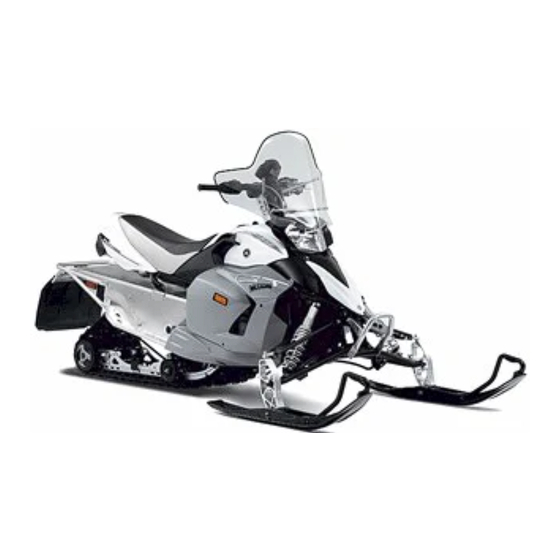
ESU00012 PZ50FX D ESCRIPTION 1 Windshield 2 Top cover 3 Steering handlebar 4 Seat 5 Passenger grip warmer switch (PZ50VT) 6 Frame 7 Backrest (PZ50VT) 8 Rear carrier (PZ50VT) 9 Storage compartment PZ50GT (PZ50FX/PZ50GT/PZ50M) 0 Tool kit A Slide rail suspension B Drive track C Skis PZ50M... - Page 18 D Right side cover PZ50FX/PZ50GT/PZ50M E Right upper cover F Side mirror (PZ50VT) G Headlights H Shroud (PZ50VT) I Left upper cover J Left side cover K Air filter case cover L Front cover (PZ50FX/PZ50GT/PZ50M) M Strap (PZ50M) N Tail/brake light O Snow flap PZ50VT...
- Page 19 P Brake lever PZ50FX/PZ50GT/PZ50M Q Parking brake lever R Grip/Thumb warmer adjustment switch S Headlight beam switch T Speedometer unit U Engine stop switch V Throttle lever W Shroud latch (PZ50VT) X Main switch Y Auxiliary DC jack (PZ50VT) Z “RESET” button [ “SELECT”...
-
Page 20: Control Functions
ESU00013 C ONTROL FUNCTIONS ESU05210 Main switch The main switch controls the following items. 1 “OFF” The ignition circuit is switched off. The key can be removed only in this position. 2 “ON” The ignition circuit is switched on. 3 “START” The starting circuit is switched on. -
Page 21: Engine Overheating Prevention System
ESU00361 Engine overheating prevention system This model is equipped with an engine overheating pre- vention system to prevent overheating when the engine is idling. When the engine has been idling for at least 3 minutes and the coolant temperature has risen above 100 °C (212 °F), the engine automatically shuts off to prevent overheating. - Page 22 CA-19E Mode Idling/ Running Trouble starting Item Throttle switch Throttle position Closed Open Open sensor T.O.R.S. Engine will operate È Idling/starting É Running Ê Trouble 1 Throttle position sensor (throttle valve position) 2 Throttle switch 3 Throttle cable a On b Off c Open d Closed...
-
Page 23: Speedometer Unit
ESU05470 Speedometer unit The speedometer unit is equipped with the following: a digital speedometer (which shows the riding speed) an odometer (which shows the total distance trav- eled) a tripmeter (which shows the distance traveled since it was last set to zero) an engine speed meter (which shows the engine speed;... -
Page 24: High Beam Indicator Light
NOTE: To switch the speedometer, odometer, and tripmeter displays between kilometers and miles, select the odometer mode “ODO”, and then push the “SELECT” button for at least 10 seconds while the snowmobile is stopped. Use the engine speed meter only when checking the snowmobile and performing basic maintenance. -
Page 25: Fuel Level Warning Indicator
The fuel level warning indicator 1, warning light 2, and all segments of the fuel meter 3 warn the rider of the above problems by flashing continuously. When this occurs, have a Yamaha dealer inspect the snowmobile as soon as possible. ESU03770... -
Page 26: Low Coolant Temperature Indicator Light
ESU04840 Low coolant temperature indicator light The low coolant temperature indicator light 1 comes on when the coolant temperature is low and informs the rider that the snowmobile must be warmed up. After the engine is started, warm it up until the indicator light goes off. -
Page 27: Coolant Temperature Warning Indicator
If the knock control system “KCS” indicator light is flashing, have a Yamaha dealer inspect the snowmobile as soon as possible. NOTE: To help prevent knocking, use premium unleaded gaso- line only. -
Page 28: Engine Stop Switch
If the self-diagnosis warning indicator, warning light, and an error code flash after the engine has been restarted, note the error code, and then have a Yamaha dealer inspect the snowmobile as soon as possible. ESU00031 Engine stop switch The engine stop switch 1 is used to stop the engine in an emergency. -
Page 29: Brake Lever
ESU00320 Brake lever The snowmobile is stopped by braking the entire drive system. Squeeze the brake lever towards the handlebar grip to stop the snowmobile. 1 Brake lever 2 Brake lever end 3 Handlebar end NOTE: When the brake lever is operated, the brake light will illu- minate. -
Page 30: Headlight Beam Switch
ESU00039 Headlight beam switch Push the headlight beam switch to change the headlight beam to high or low. 1 Headlight beam switch 2 Push 3 High beam 4 Low beam ESU05200 Grip/thumb warmer adjustment switch The grip/thumb warmer adjustment switch 1 controls the electrically heated handlebar grips and throttle lever. -
Page 31: Auxiliary Dc Jack
ESU04301 Auxiliary DC jack For PZ50VT The auxiliary DC jack is located in the front panel and can be used for accessories. NOTE: The auxiliary DC jack cannot be used if the engine is not running. 1. Start the engine. 2. -
Page 32: Shroud And Covers
CAUTION : Make sure that all cables and wires are in place when closing the shroud. WARNING Do not drive the snowmobile with the shroud open, unlatched, or removed. Keep your body and clothing away from rotating parts when servicing with the shroud open. Do not touch the hot muffler and engine during or immediately after operation. -
Page 33: Drive Guard
For PZ50VT 8 Shroud 9 Left upper cover 0 Left side cover A Right upper cover B Right side cover C Right lower cover D Air filter case cover WARNING Do not drive the snowmobile with the shroud or covers unfastened or removed. Keep your body and clothing away from rotating parts when servicing snowmobiles with the shroud open or the covers removed. -
Page 34: Backrest
ESU05450 Backrest For PZ50VT The backrest is adjustable. 1. Open the backrest zipper and loosen the backrest bolts 1. 2. Adjust the backrest angle to the desired position. 3. Tighten the bolts and close the zipper. Backrest bolt tightening torque: 19 Nm (1.9 m·kgf, 14 ft·lb) WARNING Do not sit on the backrest. -
Page 35: Pre-Operation Checks
Fuel tank capacity: 30.1 L (6.6 Imp gal, 8.0 US gal) NOTE: Your Yamaha engine has been designed to use pre- mium unleaded gasoline with a pump octane number [(R+M)/2] of 91 or higher, or a research octane num- ber of 95 or higher. -
Page 36: Engine Oil
5% of ethanol can be used, although richer jetting may be required to prevent engine dam- age. Consult a Yamaha dealer. Gasohol contain- ing methanol is not recommended. Make sure that snow or ice does not enter the fuel tank when refueling. -
Page 37: Engine Oil Level
ESU05600 Engine oil level The engine oil level should be checked before each use. CAUTION : Do not run the engine with too much or not enough oil in the oil tank. Oil could flow into the air filter case and the engine could be damaged. -
Page 38: Coolant
CAUTION : When adding the engine oil, be careful not to fill above the “H” level mark on the oil level gauge/ dipstick. Make sure that no foreign material enters the engine oil tank. 7. Insert the oil level gauge/dipstick into the oil filler hole, and then tighten it securely. -
Page 39: Throttle Lever
The T.O.R.S. will operate and the engine should run between 2,800 and 3,000 r/min. WARNING If the engine does not run between 2,800 and 3,000 r/min, stop the engine by turning the main switch to the “OFF” position and consult a Yamaha dealer. -
Page 40: Brake
Do not operate the snowmobile if you find any problems in the brake system. You could lose braking ability, which could lead to an accident. Ask a Yamaha dealer to inspect and repair the brake system. CAUTION : Make sure that the brake lever end does not project out over the handlebar end. -
Page 41: Brake Fluid Leakage
Apply the brake for a few minutes. Check to see if any brake fluid leaks out from the brake hose joints or the master cylinder. WARNING If brake fluid leakage is found, ask a Yamaha dealer for immediate repairs. CAUTION : Brake fluid may deteriorate painted surfaces or plas- tic parts. -
Page 42: Drive Guard
ESU00096 Drive guard Check the drive guard mounts for damage. Make sure that the drive guard is firmly in place. ESU00097 Drive track Check the drive track for deflection, wear, or damage. Adjust or replace if necessary. (See pages 8-29–8-31 for more details.) WARNING Do not operate the snowmobile if you find damage to... -
Page 43: Slide Runners
ESU00982 Slide runners Check the slide runners for wear and damage. If the slide runners reach the wear limit, they should be replaced. 1 Slide runners a Wear limit Wear limit height: 10.5 mm (0.41 in) CAUTION : Ride on fresh snow frequently. Operating on ice or hard packed snow will rapidly wear the slide runners. -
Page 44: Steering System
Check the handlebar for excessive free play: 1. Push the handlebar up and down and back and forth. 2. Turn the handlebar slightly to the right and left. If excessive free play is noticed, consult a Yamaha dealer. ESU01050 Lights Check the lights. -
Page 45: Tool Kit And Recommended Equipment
ESU00345 Tool kit and recommended equipment It is good practice to carry the tool kit, spare parts, and other necessary equipment with you while riding the snowmobile so that minor repairs can be done if neces- sary. The following should be carried at all times: Tool kit Flashlight Roll of plastic tape... -
Page 46: Operation
ESU00112 O PERATION ESU04640 Starting the engine WARNING Be sure to check the “SAFETY INFORMATION” section carefully before starting the engine. Make sure that the parking brake is applied. NOTE: Make sure that the engine stop switch is in the on posi- tion. -
Page 47: Break-In
CAUTION : After 800 km (500 mi) of operation, the engine oil must be changed and the oil filter cartridge replaced. If any engine trouble should occur during the engine break-in period, immediately have a Yamaha dealer check the snowmobile. -
Page 48: Riding Your Snowmobile
totally familiar with the snowmobile’s han- ESU01272 Riding your snowmobile dling and performance characteristics. Getting to know your snowmobile Set the parking brake and follow the A snowmobile is a rider active vehicle, and instructions on page 7-1 to start the your riding position and your balance are engine. -
Page 49: Turning
Turning Riding uphill For most snow surfaces, “body English” is You should practice first on gentle slopes. the key to turning. Try more difficult climbs only after you have As you approach a curve, slow down and developed your skill. As you approach a begin to turn the handlebar in the desired hill, accelerate before you start the climb, direction. -
Page 50: Riding Downhill
Riding downhill downhill leg on the seat and the foot of your uphill leg on the running board. This position will make it easier for you to shift your body weight as needed. Snow and ice are slippery, so be prepared for the possibility that your snowmobile could begin to slip sideways on the slope. -
Page 51: Hard-Packed Snow
Hard-packed snow WARNING It can be more difficult to negotiate on Drive track damage or failure could hard-packed snow as both the skis and result in loss of braking ability and drive track do not have as much traction as snowmobile control, which could cause when the snowmobile is operated on fresh an accident. -
Page 52: Maximizing Drive Track Life
Studs may catch on an object and pull out of the track, leaving tears and damage around the already weakened area. To minimize possible dam- age, consult your stud manufacturer for installation and stud pattern recommendations. Yamaha does not recommend track studding. -
Page 53: Strap
ESU02450 Strap For PZ50M The strap 1 should be used only by experienced opera- tors to assist them when traverse (side-hill) riding. WARNING Improper use of the strap on the handlebar can result in severe injury or death. Use the strap only as an operator grip point when needed to shift weight uphill to maintain balance during traverse (side-hill) riding. - Page 54 1. While the engine is idling, select the desired operat- ing position by pressing the drive select switch 1. Make sure that the drive “D” indicator light 2 or the reverse “R” indicator light 3 flashes, and then comes on and remains on. NOTE: Once the indicator light for the selected position comes on and remains on, the snowmobile can be driven.
-
Page 55: Stopping The Engine
5. Squeeze the brake lever to stop the snowmobile. 6. Apply the parking brake by moving the parking brake lever to the left. ESU00136 Stopping the engine Turn the main switch to the “OFF” position to stop the engine. 1 “OFF” WARNING Push down the engine stop switch to stop the engine in an emergency. -
Page 56: Periodic Maintenance
(if applicable). WARNING If you are not familiar with maintenance work, have a Yamaha dealer do it for you. PROPER PERIODIC MAINTENANCE OF YOUR SNOWMOBILE IS IMPORTANT IN ORDER TO ENJOY LONG, PLEASURABLE SERVICE. ESPECIALLY IMPORTANT ARE THE MAINTENANCE SERVICES RELATED TO EMISSIONS CONTROL. -
Page 57: General Maintenance And Lubrication Chart
∗ Fuel injection Adjust synchronization. Check for leakage. ∗ Exhaust system Tighten or replace gasket if necessary. ∗ It is recommended that these items be serviced by a Yamaha dealer. ESU04980 General maintenance and lubrication chart CD-32E Every Initial Pre-... - Page 58 ∗ Primary and second- Inspect weights/rollers and ary clutches bushings for wear-for primary. Inspect ramp shoes/bushings for wear-for secondary. Replace if necessary. Lubricate with specified grease. ∗ It is recommended that these items be serviced by a Yamaha dealer.
- Page 59 Tool kit and recom- Check for proper placement. 6-11 mended equipment ∗ It is recommended that these items be serviced by a Yamaha dealer. NOTE: Brake system: After disassembling the master cylinder or caliper cylinder, always change the brake fluid. Regularly check the brake fluid level and add fluid if necessary.
-
Page 60: Tool Kit
NOTE: If you do not have a torque wrench available during a service operation requiring one, take your snowmobile to a Yamaha dealer to check the torque settings and adjust them if necessary. -
Page 61: Removing And Installing The Shroud And Covers
ESU05550 Removing and installing the shroud and covers Shroud, front cover, and air filter case cover To open the shroud and remove the front cover and air filter case cover 1. Unhook the latch, and then slide the front cover upward (for PZ50FX/PZ50GT/PZ50M). - Page 62 Left side cover To remove the left side cover Loosen the quick fasteners, and then remove the left side cover. 1 Quick fastener 2 Left side cover To install the left side cover Place the left side cover in the original position, and then tighten the quick fasteners.
- Page 63 Right upper cover (for PZ50FX/PZ50GT/PZ50M) To remove the right upper cover 1. Remove the top cover. (See the above procedure.) 2. Remove the right upper cover by removing the bolts. 1 Right upper cover bolt 2 Right upper cover To install the right upper cover 1.
-
Page 64: Checking The Spark Plugs
You should periodically remove and inspect the spark plug because heat and deposits will cause a spark plug to slowly break down and erode. Consult a Yamaha dealer before chang- ing to a different type of spark plug. Specified spark plug:... - Page 65 Spark plug reach a: 19.0 mm (0.75 in) Before installing any spark plug, measure the electrode gap with a wire thickness gauge and adjust to specifica- tion. Spark plug gap b: 0.6–0.7 mm (0.024–0.028 in) When installing the spark plug, always clean the gasket surface.
-
Page 66: Adjusting The Engine Idling Speed
ESU05370 Adjusting the engine idling speed CAUTION : Be sure to have a Yamaha dealer make this adjust- ment. 1. Start the engine and warm it up. 2. Select the engine speed meter mode. (See page 5-4 for details.) 3. Remove the rubber cap 1. -
Page 67: Adjusting The High-Altitude Settings
If you plan to operate your snowmobile at an altitude different from the area where you bought it, be sure to consult a Yamaha dealer. The dealer can tell you if there are any changes necessary for the altitude where you plan to ride. -
Page 68: Changing The Engine Oil
ESU05580 Changing the engine oil It is recommended to have a Yamaha dealer change the engine oil. WARNING Engine oil is extremely hot immediately after the engine is turned off. Coming into contact with or get- ting any engine oil on your clothes could result in burns. - Page 69 8. Install the engine oil drain bolts, and then tighten them to the specified torques. Tightening torques: Crankcase engine oil drain bolt: 30 Nm (3.0 m·kgf, 22 ft·lb) Oil tank engine oil drain bolt: 16 Nm (1.6 m·kgf, 11 ft·lb) 9.
-
Page 70: Cooling System
If oil is leaking or the oil level warning indicator comes on when the engine is running, immediately turn the engine off and have a Yamaha dealer check the snowmobile. Continuing to operate the engine under such conditions could cause severe engine damage. - Page 71 Consult a Yamaha dealer. 1. Remove the top cover and the right upper cover (for PZ50FX/PZ50GT/PZ50M), or open the shroud and remove the right upper cover (for PZ50VT).
-
Page 72: Replacing The V-Belt
NOTE: If you find any leaks, consult a Yamaha dealer. 5. Install the right upper cover and the top cover (for PZ50FX/PZ50GT/PZ50M), or install the right upper cover and close the shroud (for PZ50VT). ESU05540 Replacing the V-belt WARNING Have a Yamaha dealer replace the V-belt and adjust the gap between the secondary fixed sheave and the secondary sliding sheave. -
Page 73: Checking The Drive Chain Housing Oil Level And The Drive Chain Tension
7. Rotate the secondary sliding sheave clockwise 4 and push 5 it so that it separates from the secondary fixed sheave. 8. Install the V-belt 6 between the secondary sliding and secondary fixed sheaves. 9. Install the drive guard. 10. Install the left side cover (for PZ50FX/PZ50GT/ PZ50M), or install the left side cover and the left upper cover, and then close the shroud (for PZ50VT). -
Page 74: Checking The Brake Pads
5. Install the right side cover. ESU00174 Checking the brake pads Check the brake pads for wear. If the brake pads reach the wear limit, ask a Yamaha dealer to replace them. 1 Brake pad wear indicator Wear limit a: 1.5 mm (0.06 in) -
Page 75: Checking The Parking Brake Pads
Checking the parking brake pads Check the parking brake pads for wear by measuring the thickness of the pads. If the parking brake pads reach the wear limit, ask a Yamaha dealer to replace them. Wear limit a: 1.2 mm (0.05 in) Adjustment As the parking brake pads wear, adjustment may be nec- essary to ensure proper brake performance. -
Page 76: Changing The Brake Fluid
Water will significantly lower the boiling point of the fluid and may result in vapor lock. If the brake fluid level goes down, consult a Yamaha dealer. CAUTION : Brake fluid may deteriorate painted surfaces or plas- tic parts. - Page 77 ESU03851 Adjusting the ski spring preload The spring preload can be adjusted by turning the spring preload adjuster 1. For PZ50M/PZ50VT CD-10E Spring adjuster position 2 Hard Soft 3 Preload Standard CAUTION : The left and right ski spring preload must be set to the same pressure.
- Page 78 Do not deform or damage the shock absorber in any way. Do not dispose of a worn or damaged shock absorber by yourself. Take the unit to a Yamaha dealer. ESU04750 Adjusting the ski damping forces...
- Page 79 Do not deform or damage the shock absorber in any way. Do not dispose of a worn or damaged shock absorber by yourself. Take the unit to a Yamaha dealer. 8-24...
- Page 80 ESU04213 Adjusting the rear suspension spring preload The spring preload can be adjusted by turning the spring preload adjuster 1 on each shock absorbers. For PZ50GT/PZ50M CD-13E Spring adjuster position Preload Soft Hard È Standard (front) For PZ50VT CD-13E Spring adjuster position Preload Soft Hard...
- Page 81 WARNING Be sure to have a Yamaha dealer make this adjust- ment. This shock absorber contains highly pressurized nitrogen gas. It could explode by improper handling, causing injury, or property damage. Do not tamper with or attempt to open the shock absorber.
- Page 82 Do not deform or damage the shock absorber in any way. Do not dispose of a worn or damaged shock absorber by yourself. Take the unit to a Yamaha dealer. ESU04221 Adjusting the control rods For PZ50VT The weight transfer can be adjusted by turning the con- trol rod adjusting nut 1.
- Page 83 WARNING Never adjust the control rods beyond the maximum range indicated on the rods with red paint 3. c Adjustable range d Standard position ESU04342 Adjusting the 2-up adjusting block spring force For PZ50VT The spring force can be adjusted by changing the posi- tion of the 2-up adjusting blocks.
-
Page 84: Adjusting The Drive Track
ESU03532 Adjusting the drive track WARNING A broken track, track fittings or debris thrown by the drive track could be dangerous to an operator or bystanders. Observe the following precautions: Do not allow anyone to stand behind the snow- mobile when the engine is running. When the rear of the snowmobile is raised to allow the drive track to spin, a suitable stand must be used to support the rear of the snowmo-... - Page 85 Adjusting the drive track WARNING Be sure to have a Yamaha dealer make this adjustment. Support the snowmobile securely on a suitable stand before working underneath the snowmo- bile. Operate the engine in a well-ventilated area. 1. Lift the rear of the snowmobile onto a suitable stand to raise the drive track off the ground.
-
Page 86: Aligning The Skis
2. Check the following for ski alignment: a.Skis are facing forward. b.Ski toe-out (1 – 2) is within specification. Ski toe-out (1 – 2): 0–15 mm (0–0.59 in) 3. If the alignment is not correct, consult a Yamaha dealer. 8-31... -
Page 87: Lubrication
Apply a dab of grease onto the cable end only. Do not grease the throttle cable because it could become frozen, which could cause loss of control. 2 Rear suspension WARNING Be sure to have a Yamaha dealer lubricate the front and rear suspensions. 8-32... -
Page 88: Replacing A Headlight Bulb
ESU05560 Replacing a headlight bulb 1. Remove the top cover (for PZ50FX/PZ50GT/PZ50M) or open the shroud (for PZ50VT). (See pages 8-6– 8-9 for removal procedures.) 2. Disconnect the headlight coupler. 3. Remove the bulb holder cover. 4. Unhook the bulb holder by pushing it in, then down- ward. -
Page 89: Adjusting The Headlight Beams
To charge the battery Have a Yamaha dealer charge the battery as soon as possible if it seems to have discharged. Keep in mind that the battery tends to discharge more quickly if the snowmobile is equipped with electrical accessories. -
Page 90: Replacing A Fuse
9 Spare fuses (20 A, 15 A, 10 A, 7.5 A, 4 A, 3 A) 4. Connect the negative battery lead. 5. Install the right side cover. NOTE: If the fuse immediately blows again, ask a Yamaha dealer to inspect the snowmobile. 8-35... -
Page 91: Troubleshooting
Worn or damaged piston and cylinder No fuel in tank ... Supply fuel..Ask a Yamaha dealer to inspect. Clogged fuel line ... Clean fuel line. Clogged injector ... Ask a Yamaha B. Starting the engine with a dis- dealer to inspect. - Page 92 10. Disconnect the red (+) jumper cable 2. Air in cooling system ... Bleed the cool- from the positive (+) terminal of the ing system or ask a Yamaha dealer to booster battery. inspect. 11. Disconnect the red (+) jumper cable 3.
- Page 93 3. Tight, loose, or broken drive chain ..Replace. Ask a Yamaha dealer to inspect. 4. Worn or damaged idler wheels or shafts ... Ask a Yamaha dealer to H. V-belt twists inspect. 1. Improper V-belt ... Replace with the 5.
-
Page 94: Storage
Make sure that the battery terminals content in the fuel increases the chance for are tight. water to enter the engine. Use Yamaha Stor-Rite Engine Fogging Oil, or an equiva- lent fogging oil, to protect both the com- bustion chamber and crankshaft from corrosion. - Page 95 To charge a sealed-type (MF) battery, and tuned by a Yamaha dealer. The dealer a special (constant-voltage) battery has the experience and training to help you charger is required. Using a conven-...
-
Page 96: Specifications
ESU00228 S PECIFICATIONS 1 1 - ESU00229 Dimensions CS-01E PZ50FX/PZ50GT/PZ50M/PZ50VT Overall length 2,820 mm (111.0 in): PZ50FX/PZ50GT 3,195 mm (125.8 in): PZ50M 3,150 mm (124.0 in): PZ50VT Overall width 1,215 mm ( 47.8 in): PZ50FX/PZ50GT/ PZ50VT 1,165 mm ( 45.9 in): PZ50M Overall height 1,190 mm ( 46.9 in): PZ50FX 1,340 mm ( 52.8 in): PZ50GT/PZ50M... -
Page 97: Chassis
ESU00231 Chassis CS-03E PZ50FX/PZ50GT/PZ50M/PZ50VT Drive track and suspension: Track Molded rubber, fiber glass rod reinforced Width 356 mm (14.0 in): PZ50FX/PZ50GT/ PZ50M 381 mm (15.0 in): PZ50VT Track deflection 30–35 mm (1.18–1.38 in)/ 100 N (10 kg, 22 lb) Length on ground 769 mm (30.3 in): PZ50FX/PZ50GT 1,084 mm (42.7 in): PZ50M 985 mm (38.8 in): PZ50VT... -
Page 98: Electric
PZ50FX/PZ50GT/PZ50M/PZ50VT Brake: Type Hydraulic disc type (ventilated disc) Operation Handle lever, left hand operated Throttle: Operation Handle lever, right hand operated ∗1 Subject to change according to elevation settings. ∗2 Usually achieved after approximately 800 m (0.5 mi) traveled. ESU00232 Electric CS-04E PZ50FX/PZ50GT/PZ50M/PZ50VT... - Page 99 –MEMO–...
- Page 100 (10A) (20A) (15A) (7.5A) (20A) (3A) (4A) 12-1...
- Page 101 12-2...
- Page 102 –MEMO–...
- Page 104 YAMAHA MOTOR CO., LTD. PRINTED IN JAPAN PRINTED ON RECYCLED PAPER 2006.06 - 3.1×2 CR...
Need help?
Do you have a question about the PZ50FXW and is the answer not in the manual?
Questions and answers