Table of Contents
Advertisement
CAUTION
RISK OF ELECTRIC SHOCK
DO NOT OPEN
The lightning flash with arrowhead symbol, within an equilateral triangle, is intended to alert the user to the
presence of uninsulated "dangerous voltage" within the product's enclosure that may be of sufficient
magnitude to constitute a risk of electric shock to persons.
The exclamation point within an equilateral triangle is intended to alert the user to the presence of
important operating and maintenance (servicing) instructions in the literature accompanying the
appliance.
WARNING: TO PREVENT FIRE OR SHOCK HAZARD, DO NOT EXPOSE
THIS APPLIANCE TO RAIN OR MOISTURE.
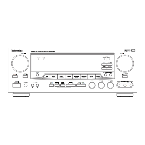
DDR 95
AV Digital Surround Receiver
FUNCTION
ION
TAPE 2
MUTING G
MONITOR
OR
POWER R
STANDBY/ON
/ON
PHONE S
PHONES
CAUTION: TO REDUCE THE RISK OF ELECTRIC SHOCK, DO NOT REMOVE COVER (OR
BACK). NO USER-SERVICEABLE PARTS INSIDE. REFER SERVICING TO QUALIFIED
SERVICE PERSONNEL.
STANDBY
MUTING G
SLEEP
BASS
TEST
SPEAK ER
SPEAKER
LEVEL
LEVEL
ADJUST
ADJUST
DELAY TIME
SPEAKERS
ERS
TONE
CONFIG G
SELECT
SELEC T
CENTER R
REAR
A
B
OWNER'S MANUAL
VOLUME E
DIGITAL
COAXI AL OPTICAL
COAXIAL
OPTIC AL
1
2 2
3
BAND
FM MODE
DE
MODE
MODE
MEMORY
BASS BOOST
BOOST
OFF
OFF
ON
TREBLE
LE
BALANCE
NCE
VIDEO
L
AUDIO
R R
L L
R
Advertisement
Table of Contents

Related Manuals for TECHWOOD DDR 95


Summary of Contents for TECHWOOD DDR 95
- Page 1 DDR 95 AV Digital Surround Receiver FUNCTION VOLUME E DIGITAL STANDBY MUTING G COAXIAL COAXI AL OPTICAL OPTIC AL BAND FM MODE MODE MODE MEMORY SLEEP TAPE 2 BASS BOOST BOOST MUTING G MONITOR BASS TREBLE BALANCE POWER R STANDBY/ON...
-
Page 2: Important Safety Instructions
IMPORTANT SAFETY INSTRUCTIONS CAUTION: “Note to CATV system installer: • This reminder is provided to call the CATV system installer’s Read all of these instructions. • attention to Section 820-40 of the NEC which provides guidelines Save these instructions for later use. •... -
Page 3: Table Of Contents
CONTENTS PRECAUTIONS ..................4 CONNECTIONS Audio Connections . -
Page 4: Precautions
PRECAUTIONS Read This Before Operating TO THE USER Choose the installation location of your unit carefully. This equipment has been tested and found to Avoid placing it in direct sunlight or close to a source of comply with the limits for a A/V receiver, pursuant heat. -
Page 5: Audio Connections
CONNECTIONS CAUTION : Audio connection cords Do not plug the power cord of any component into AC outlets and do not turn their POWER switches on until all connections have been performed. The cable connectors should be fully inserted into the jacks. Loose connections may cause hum and noise. - Page 6 CONNECTIONS S-VIDEO signal jacks Connecting Video Equipment Connect the TV monitor S-VIDEO IN jack to the MONITOR OUT jack. AUDIO signal jacks Connect the video deck (VCR) S-VIDEO OUT jack to the Connect the video deck (VCR) LINE output (AUDIO S-VIDEO VCR IN jack.
- Page 7 Notes : Connecting the PRE OUT jacks If a speaker is connected directly to the PRE OUT jack without an amplifier connected, no sound comes This unit is equipped with Subwoofer and Center from the speaker. PREOUT jacks. These jacks allow connection off an Subwoofer speakers are optional and are not optional powered subwoofer and connection of the required.
-
Page 8: Video Connections
CONNECTIONS VIDEO CONNECTIONS FM Outdoor Antenna In an area where FM signals are weak, it will be necessary to use a 75-ohm unbalanced-type outdoor FM antenna using the provided matching transformer, as shown. Generally, a 3-element antenna will be sufficient; if you live in an area where the FM signals are particularly weak, it may be necessary to use one with 5 or more elements. -
Page 9: Connecting Speaker Systems
AM Antenna Connecting Speaker Systems Caution : AM Indoor Loop Antenna To avoid damaging the speakers by inputting a sudden A high-performance AM loop antenna provided with the high-level signal, be sure to switch the power off before receiver is sufficient for good reception in most areas. connecting the speakers. -
Page 10: Controls And Indicators
CONTROLS AND INDICATORS Front Panel 33 34 24 7 FUNCTION VOLUME DIGIT COAXIAL OPTICAL OPTICAL ANDBY MUTING BAND FM MODE MODE MEMOR SLEEP APE 2 APE 2 BASS BOOST MUTING MONIT MONIT BASS TREBLE BALANCE POWER VIDEO AUDIO ANDBY/ON TEST SPEAKER LEVEL ADJUST... - Page 11 Remote control Unit FRONT Panel and REMOTE POWER STANDBY/ON Button FUNCTION (Source) Selector SURROUND MODE Buttons REMOTE SENSOR Window Multi-Function Display Numeric Keys (TUNER/CD/DVD) BAND Selector Button FM MODE Button TUNING/PRESET Buttons BALANCE Control VIDEO 1 VIDEO 2 VIDEO 3 VIDEO 4 MASTER VOLUME Control BASS BOOST Switch...
-
Page 12: Audio Operations
AUDIO OPERATIONS Basic Operations Note : The following points apply throughout the “AUDIO and VIDEO OPERATIONS” sections unless otherwise noted. To simplify explanations, instructions refer to names of buttons and controls on the front panel, making no mention of the use of remote control unit. To listen to a source other than TAPE 2 (tape deck), press the TAPE 2 MONITOR button to the OFF position (the TAPE... -
Page 13: Audio Adjustments
Audio Adjustments SURROUND Mode MASTER VOLUME MUTE BALANCE FUNCTION (Source) Selector DIGITAL INPUT SURROUND ON/OFF BASS/TREBLE SPEAKERS (Tone controls) SURROUND MODE Button POWER BASS BOOST (STANDBY/ON) The Surround mode changes whenever you press this button. For digital equipment : CD, TV/ VIDEO 2, AUX/ VIDEO 3, POWER STANDBY/ON Button DVD/VIDEO 4. -
Page 14: Radio Reception
AUDIO OPERATIONS Radio Reception Manual Tuning Auto Tuning FM MODE FM MODE POWER ON POWER ON Manual Tuning is generally used to tune to stations broadcasting a signal that is too weak to be received by 1. Select the TUNER mode by turning the FUNCTION Auto Tuning. -
Page 15: Tuning
Direct Tuning Tuning Using this method, the required frequency is input This feature is used to store FM, AM broadcasting from directly, using the numeric keys on the remote control Channel 1 to 30 respectively. You can set 30 AM and 30 unit. -
Page 16: Listening To Records And Compact Discs
AUDIO OPERATIONS Manual Memory Presetting Listening to Records and Compact Discs POWER ON POWER ON Turntable 1. Select the TUNER mode by turning the FUNCTION CD Player selector. 2. Select AM or FM by pressing the BAND selector 1. Select the PHONO or CD mode by turning the button. -
Page 17: Playing Tape 2 Deck
Playing TAPE 2 Deck Dubbing from TAPE 2 to MD/TAPE 1 TAPE Indicator Lit TAPE Indicator Lit POWER ON POWER ON Recording Tape Deck 2 Tape Deck 2 Tape Deck 1 1. Set the TAPE 2 MONITOR button to ON ; the TAPE 1. -
Page 18: Video Operations
VIDEO OPERATIONS Playing Video Sources Recording with a Video Deck Note : Tape Dubbing (from TV/VIDEO 2, AUX/VIDEO 3 For playing video software using a certain Surround or DVD/VIDEO 4 to VCR/VIDEO 1) Effect function, refer to the SURROUND EFFECTS section. -
Page 19: Surround Effects
SURROUND EFFECTS When you use the surround function, the sound creates a DOLBY PRO LOGIC “live” atmosphere such as that experienced in movie theaters, disco, stadium and concert halls. Use this mode when playing movie or music video software which carries the DOLBY SURROUND mark. -
Page 20: Speaker Positioning
SURROUND EFFECTS Speaker Positioning Speaker Configuration This installation positions of speakers differ according to the size, and acoustics of the listening room. While actually listening to a program source, try various speaker positions to determine which layout provides the best surround effect. Speaker layout example when using SURROUND MODE Front Speakers... -
Page 21: Delay Time/Effect
b. When in Dolby PRO LOGIC Mode, Channel Level Choose from: Front Speaker : LARGE SMALL Center Speaker : LARGE SMALL NONE Rear Speaker : LARGE SMALL c. When in 3 Stereo Mode, Choose from: Front Speaker : LARGE SMALL Center Speaker : LARGE SMALL SUBWOOFER output... -
Page 22: Playing Surround Sound
BACK-UP SYSTEM SURROUND EFFECTS Playing Surround Sound Back-up Memory Function This function stores the preset memory and most-recent memory functions. In the event of a power failure, or if the power cord of this unit is disconnected from the electric outlet, the back-up memory will save the preset memory and most-recent memory functions for approximately 3 days. -
Page 23: Osd (On Screen Display)
OSD (ON SCREEN DISPLAY) When your Techwood AV Digital Surround Receiver is 2) When the OSD ON/OFF button on the remote control is connected to a television, you can operate the unit with pressed, a display appears which shows the current... - Page 24 OSD (ON SCREEN DISPLAY) 4) Entering INPUT SELECTOR from the MAIN MENU An asterisk (*) appears opposite the input currently brings up a display that allows you to select the video selected. To change this selection, move the arrow with input that you'd like to monitor.
- Page 25 When you are monitoring PHONO, TUNER, MD/TAPE When you are monitoring ANALOG input, use the 1, or VCR/VIDEO 1, use the left/right buttons to select left/right buttons to select one of these SURROUND one of these SURROUND MODE choices: MODE choices: SURROUND SURROUND R.LEVEL...
- Page 26 OSD (ON SCREEN DISPLAY) Your choices will vary according to the SURROUND 8) Entering LANGUAGE from the MAIN MENU brings up a MODE you are using. Use the up/down buttons to move menu that allows you to change the language of the on the arrow and the right/left buttons to make your screen menus.
- Page 27 Once this display appears, pressing the CENTER or REAR AUTOMATIC OSD FUNCTIONS DELAY TIME, or the CENTER or REAR LEVEL buttons will enable you to change the function of the button pressed using the right/left buttons. Pressing SUB W ON/OFF or If the receiver is connected to a television with a video cable from the monitor out jacks, the following SUB W LEVEL will allow you to change the sub-woofer...
-
Page 28: Remote Control Unit
REMOTE CONTROL UNIT Using the Remote Control Unit Battery Installation By using the provided remote control unit, the receiver and some other components including DVDC96, DVDC 95, CDC 86, CDC 85 and TDX 85 can be controlled from your listening position. To use the remote control unit, point it at the REMOTE SENSOR window of the receiver (or other component). -
Page 29: Troubleshooting
TROUBLESHOOTING To determine any problem with your receiver, always check the most obvious possible causes first. If any problem still remains after your have checked the items below, consult your nearest TECHWOOD dealer. Problem Probable Cause Remedy Amplifier When listening to the music in stereo, Speakers are connected wrong. -
Page 30: Specifications
SPECIFICATIONS Amplifier Section FM Tuner Section Output Power (Front) : (Without notes 100.1 MHz, 65 dBf) F.T.C. Rating: Tuning Range : 130 watts RMS per channel minimum, both channels 87.5 MHz - 108.0 MHz (100 kHz steps) driven into 8 ohms from 20 Hz to 20 kHz with no more Usable Sensitivity (IHF) : than 0.09% total harmonic distortion Mono : 11.2 dBf... - Page 31 WELTON U.S.A. 11625 COLUMBIA CENTER DR. SUITE 100 DALLAS, TEXAS 75229 PHONE: 972-243-5602 KQX1A603Z FAX: 972-243-5958...
Need help?
Do you have a question about the DDR 95 and is the answer not in the manual?
Questions and answers