Table of Contents
Advertisement
Quick Links
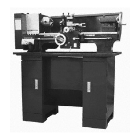
9" X 20" geared head, belt
driven, bench lathe
Set up and Operating inStructiOnS
distributed exclusively by harbor Freight tools
3491 Mission Oaks Blvd., Camarillo, CA 93011
visit our website at: http://www.harborfreight.com
read this material before using this product.
Failure to do so can result in serious injury.
Save thiS Manual.
©
Copyright
2008 by Harbor Freight Tools
artwork contained herein may be reproduced in any shape or form without the express written
consent of Harbor Freight Tools. Diagrams within this manual may not be drawn proportionally. Due
to continuing improvements, actual product may differ slightly from the product described herein.
For technical questions or replacement parts, please call 1-800-444-3353.
Model
45861
®
. All rights reserved. No portion of this manual or any
®
.
Advertisement
Chapters
Table of Contents

Related Manuals for Central Machinery CENTRAL MACHINERY 45861


Summary of Contents for Central Machinery CENTRAL MACHINERY 45861
- Page 1 Harbor Freight Tools. Diagrams within this manual may not be drawn proportionally. Due to continuing improvements, actual product may differ slightly from the product described herein.
-
Page 2: Table Of Contents
SaFetY inFOrMatiOn ... 3 general pOwer tOOl SaFetY warningS... 3 lathe SaFetY warningS ... 5 grOunding ... 6 grOunded tOOlS: tOOlS with three prOng plugS ... 6 eXtenSiOn cOrdS ... 7 SYMbOlOgY ... 7 SpeciFicatiOnS ... 9 unpacking ... 9 liSt OF cOntentS ... -
Page 3: Important Safety Information
Save thiS Manual Keep this manual for the safety warn- ings and precautions, assembly, operat- ing, inspection, maintenance and cleaning procedures. Write the product’s serial number in the back of the manual near the assembly diagram (or month and year of purchase if product has no number). - Page 4 Unmodified plugs and matching out- lets will reduce risk of electric shock. avoid body contact with grounded surfaces such as pipes, radiators, ranges and refrigerators. There is an increased risk of electric shock if your body is grounded. do not expose power tools to rain or wet conditions.
-
Page 5: Lathe Safety Warnings
Safety warnings Maintain labels and nameplates on the tool. These carry important safety information. If unreadable or miss- ing, contact Harbor Freight Tools for a replacement. Do not run the Lathe without its cov- ers and guards in place. -
Page 6: Grounding
avoid electrical shock. • Any power cord must be properly grounded. Ground Fault Circuit Inter- rupter (GFCI) should also be imple- mented – it prevents sustained elec- trical shock. Some dust created by power sand- ing, sawing, grinding, drilling, and other construction activities, contains chemicals known [to the State of Cali- fornia] to cause cancer, birth defects... -
Page 7: Extension Cords
of electric shock. (See 3-prong plug and Outlet.) The grounding prong in the plug is connected through the green wire in- side the cord to the grounding system in the tool. The green wire in the cord must be the only wire connected to the tool’s grounding system and must never be attached to an electrically “live”... - Page 8 Symbology Underwriters Laboratories, Inc. Volts Alternating Current Amperes No Load Revolutions per Minute n 0 xxxx/min. (RPM) SKU 45861 For technical questions, please call 1-800-444-3353. Page 8...
-
Page 9: Specifications
When unpacking, check to make sure that the item is intact and undamaged. If any parts are missing or broken, please call Harbor Freight Tools at the number shown on the cover of this manual as soon as possible. proper lubrication is essential. To... -
Page 10: Functions
Lathe during operation. The cabinet recommend- ed for use with this Lathe is SKU 46378; this product is available from Harbor Freight Tools. Use a hoist or a forklift to lift the Lathe onto the cabinet or workbench. - Page 11 Faceplate (or chuck) ways carriage handwheel Follow rest Steady rest apron handwheel SKU 45861 For technical questions, please call 1-800-444-3353. lathe tailstock tool holder compound cross Slide halfnut carriage lever tool tailstock lock lock cross Slide gear gear engage...
- Page 12 A clamping device for hold- ing work in the lathe or for holding drills in the tailstock. compound: Movable platform where the tool post is mounted; it can...
- Page 13 Swing: A dimension representing the largest diameter workpiece that a lathe can rotate. The 9x20 lathe has a 9” swing, meaning that the maximum size workpiece that can rotate without hitting the bed is 9” in diameter.
-
Page 14: Spindle Speeds
stock barrel should protrude about 1/2’’ and not more than 3’’. To remove the Live Center, back the tailstock barrel all the way into the casting. The Live Center will pop out; catch it when it comes out to avoid damaging it. - Page 15 Switch rotation while running lathe. Feed rate The Feed Rate Lever (above) chang- es the number of threads-per-inch (TPI) that can be cut. The plate on the machine and the following charts list typical settings.
-
Page 16: General Operating Instructions
1.25 1.5 1.75 2 general Operating instructions Every ten hours of operation, lubri- cate the lathe’s gears and ways with white lithium grease, as directed in the Mainte- nance Section of this manual. The Lathe can perform a wide variety of operations;... - Page 17 The tip of the cutting tool must be at the centerline of the lathe, or the work will be marred. Clamp the toolpost in place and...
-
Page 18: Thread Cutting
advancing the drill twice its diameter, back the drill out and clean off shav- ings before continuing. Continue until the desired depth is drilled. turning Turning is the removal of metal from the outer diameter of a cylindrical work- piece to reduce the diameter and to pro- duce a smooth finish on the metal. -
Page 19: Servicing
Maintenance and Servicing Procedures not specifically explained in this manual must be performed only by a qualified technician. tO prevent SeriOuS injurY FrOM accidental OperatiOn: turn the power Switch of the tool to its “OFF” position and unplug the tool from its electrical outlet before performing any inspection, maintenance, or cleaning... -
Page 20: Please Read The Following
Wipe down the ways and slides after each use and lubricate with white lithium grease. Applying oil to the bedways and other metal parts will protect the Lathe from rusting and pitting. pleaSe read the FOllOwing careFullY THE MANUFACTURER AND/OR DISTRIBUTOR... -
Page 21: Headstock Parts List
headStOck partS liSt part description Headstock Flange Joint Spindle Gasket Bearing Cover Spacing Ring Gear Pulley Bushing Set Screw M4x6 Nut M28 Set Screw M4x10 Shaft Spacing Ring Set Screw M4x6 Bushing Gear Washer Oil Feeder Gear Gear record product’s Serial number here: note: If product has no serial number, record month and year of purchase instead. -
Page 22: Drive Parts List
drive partS liSt part description Bracket Plate Screw M8x20 Belt Pulley Shaft Washer Spring Washer Nut M10 Bushing Snap Ring Washer Spring Ball Pulley Pulley Washer Snap Ring Oil Feeder Spacer Collar Motor Pulley Washer note: When ordering parts from this list be sure to include the correct suffix. note: Some parts are listed and shown for illustration purposes only, and are not avail- able individually as replacement parts. -
Page 23: Drive Diagram
drive diagraM note: When ordering parts from this dia- gram be sure to include the correct “A” suffix. REV 08i SKU 45861 For technical questions, please call 1-800-444-3353. Page 23... -
Page 24: Tensioning Roller Parts List
tenSiOning rOller partS liSt part description Washer Bolt Lever Bracket Lever Bearing Roller Washer Snap Ring Snap Ring Washer Nut M10 Washer note: When ordering parts from this list be sure to include the correct suffix. note: Some parts are listed and shown for illustration purposes only, and are not avail- able individually as replacement parts. -
Page 25: Quadrant Parts List
Quadrant partS liSt part description Bracket T-nut Washer Shaft Bushing Gear Gear Washer Oil Feeder Washer Gear note: When ordering parts from this list be sure to include the correct suffix. note: Some parts are listed and shown for illustration purposes only, and are not avail- able individually as replacement parts. -
Page 26: Motor Housing Parts List
MOtOr hOuSing partS liSt part description E-housing Screw Lock Washer Cover Clip Condenser Lock Nut note: When ordering parts from this list be sure to include the correct suffix. note: Some parts are listed and shown for illustration purposes only, and are not avail- able individually as replacement parts. -
Page 27: Bed Parts List
bed partS liSt part description Rack Screw M4x8 Head Screw Bracket Oil Feeder Screw M6x20 note: When ordering parts from this list be sure to include the correct suffix. note: Some parts are listed and shown for illustration purposes only, and are not avail- able individually as replacement parts. -
Page 28: Gear Box Parts List
gear bOX partS liSt part description Gear Box Shaft Bushing Gear 28T Gear 26T Gear 24T Gear 23T Gear 22T Gear 20T Gear 19T Gear 18T Gear 16T Bushing Snap Ring Shaft Gear 16T Shaft Gear 36T Set Screw M5x10 note: When ordering parts from this list be sure to include the correct suffix. -
Page 29: Gear Box Diagram
gear bOX diagraM note: When ordering parts from this dia- gram be sure to include the correct “G” suffix. SKU 45861 For technical questions, please call 1-800-444-3353. Page 29... -
Page 30: Apron Parts List
aprOn partS liSt part description Apron Cover Bracket Worm Key 3x25 Cap Screw M6x25 Feed Screw Nut M4 Set Screw M4x12 Ball Spring Handle Set Screw M6x6 Washer Screw M6x8 Gear 12T Spring Pin 4x30 Gear 43T Handle note: When ordering parts from this list be sure to include the correct suffix. note: Some parts are listed and shown for illustration purposes only, and are not avail- able individually as replacement parts. -
Page 31: Apron Parts List Continued
aprOn partS liSt cOntinued part description Shaft Key 4x11 Gear 41T Ring Half Nut Locking Cam Guide Ring Cap Screw M4x16 Set Screw M5x25 Nut M5 Control Plate Joint Plate Cap Screw M4x20 Cap Screw M5x16 note: When ordering parts from this list be sure to include the correct suffix. note: Some parts are listed and shown for illustration purposes only, and are not avail- able individually as replacement parts. -
Page 32: Saddle And Cross Slide Parts List
Saddle and crOSS Slide partS liSt part description Saddle Cross Slide Lead Screw Bracket Screw M6x15 Plate Rivet 2x5 Graduated Ring Key 3x13 Spring Hand Wheel Set Screw M8x6 Handle Slide Guide Bushing Screw M6x12 Screw M4x8 note: When ordering parts from this list be sure to include the correct suffix. note: Some parts are listed and shown for illustration purposes only, and are not avail- able individually as replacement parts. -
Page 33: Saddle And Cross Slide Diagram
Saddle and crOSS Slide diagraM note: When ordering parts from this dia- gram be sure to include the correct “J” suffix. SKU 45861 For technical questions, please call 1-800-444-3353. Page 33... -
Page 34: Tool Post Parts List
tOOl pOSt partS liSt part description Longitudinal Slide Swivel Base Clamping Ring Micrometer Pan Lead Screw Nut Adjusting Screw Screw T-cap Screw Screw M5x10 Screw M6x12 Set Screw M4x10 Nut M4 Nut M6 Lock Pin 3x8 note: When ordering parts from this list be sure to include the correct suffix. note: Some parts are listed and shown for illustration purposes only, and are not avail- able individually as replacement parts. -
Page 35: Tailstock Diagram
tOOl pOSt diagraM note: When ordering parts from this dia- gram be sure to include the correct “K” suffix. SKU 45861 For technical questions, please call 1-800-444-3353. Page 35... -
Page 36: Travelling Rest Parts List
travelling reSt partS liSt part description Rest Screw Spring Washer Nut M8 note: When ordering parts from this list be sure to include the correct suffix. note: Some parts are listed and shown for illustration purposes only, and are not avail- able individually as replacement parts. -
Page 37: Steady Rest Parts List
SteadY reSt partS liSt part description Rest Screw Adjustment Screw note: When ordering parts from this list be sure to include the correct suffix. note: Some parts are listed and shown for illustration purposes only, and are not avail- able individually as replacement parts. SKU 45861 For technical questions, please call 1-800-444-3353. -
Page 38: Tail Stock Parts List
tail StOck partS liSt part description Tailstock Ram Lead Screw Bushing Plate Handwheel Lever Clamp Guide Pin Micrometer Collar Feed Spring Tailstock note: When ordering parts from this list be sure to include the correct suffix. note: Some parts are listed and shown for illustration purposes only, and are not avail- able individually as replacement parts. -
Page 39: Wiring Diagram
wiring diagraM SKU 45861 For technical questions, please call 1-800-444-3353. Page 39... - Page 40 wiring diagraM SKU 45861 For technical questions, please call 1-800-444-3353. Page 40...
-
Page 41: Limited 1 Year / 90 Day Warranty
(90 days if used by a professional contractor or if used as rental equipment). Harbor Freight Tools also warrants to the original purchaser, for a period of ninety days from date of purchase, that all other parts and components of the product are free from defects in materials and workmanship.
Need help?
Do you have a question about the CENTRAL MACHINERY 45861 and is the answer not in the manual?
Questions and answers
Where do i order parts for my lathe??