Advertisement
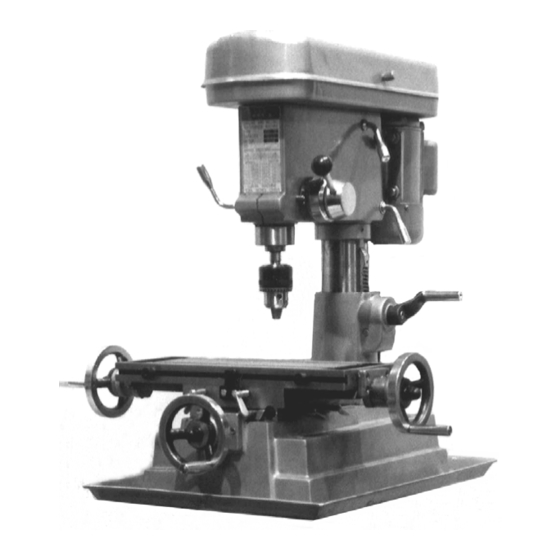
Drill / Mill Machine
A s s e m b l y & O p e r a t i n g I n s t r u c t i o n s
Copyright
No portion of this manual or any artwork contained herein may be reproduced in any
manner, shape or form without the express written consent of Harbor Freight Tools.
For technical questions and replacement parts, please call 1-800-444-3353.
12 Speed
Model 42976
www.HarborFreight.com
2000 by Harbor Freight Tools
42976
42976
42976
42976
. All Rights Reserved.
®
Advertisement
Table of Contents

Related Manuals for Central Machinery 42976


Summary of Contents for Central Machinery 42976
- Page 1 2000 by Harbor Freight Tools No portion of this manual or any artwork contained herein may be reproduced in any manner, shape or form without the express written consent of Harbor Freight Tools. For technical questions and replacement parts, please call 1-800-444-3353.
-
Page 2: Specifications
* For fine adjustment, use a dial test indicator (not included) mounted either to the table or workpiece, and reference a point on the chuck or quill colar that is convenient. Loosen the Clamp Handle (#83) slightly, then tap the chuck feed lever lightly, as you observe the indicator dial. Page 2 SKU # 42976 SPECIFICATIONS Drill Capacity:... - Page 3 12. REMOVE ADJUSTING KEYS AND WRENCHES. Be sure that keys and adjusting wrenches are removed from the tool or machine work surface before operation. 13. AVOID UNINTENTIONAL STARTING. Be sure that you are prepared to begin work before turning the start switch on. Page 3 SKU # 42976...
- Page 4 Do not use the tool if any switch does not turn on and off properly. 17. REPLACEMENT PARTS AND ACCESSORIES. When servicing, use only identical replacement parts intended for use with this tool. Replacement parts are available from Harbor Freight Tools. Use of any other parts will void the warranty.
- Page 5 FEATURES AND CONTROLS OF THE #42976 DRILL / MILL MACHINE 1. Column 2. Gear Strip 3. Head Crank 4. Vertical Head Lock 5. Chuck Feed Lever 6. Chuck Travel Limit Screw 7. Reference Scale 8. Chuck Fixing Lever 9. Chuck 10.
-
Page 6: Unpacking And Installation
Before operation, it is critical to level the work table both lengthwise and crosswise, using a precision level. It will not be possible to maintain accuracy of machined parts if the mill is not properly leveled. Page 6 SKU # 42976 UNPACKING AND INSTALLATION... -
Page 7: Extension Cords
AWG rating. Every cord must meet the AWG rating. Use the chart below to determine what AWG rating is required for your situation. Cord length is rated in feet. Harbor Freight Tools can supply UL listed and outdoor rated cords in most AWG ratings as needed. -
Page 8: Basic Operation
NOTE: the largest bit size capacity of this Chuck is 5/8” diameter. Insert the Drill Bit into the Chuck. Turn the Chuck Key clockwise to tighten the jaws around the drill bit shaft. Ensure that the drill bit is seated securely before starting. - Page 9 Rotate it slightly clockwise to loosen the gib strip. Adjust the gib strip bolt until very slight drag is felt when moving the table. Page 9 SKU # 42976 Figure 3. Table Control Wheel and Butterfly Lock Bolts. Figure 4. Gib StripAdjustment.
-
Page 10: Troubleshooting
The motor may be burned out. After a long period of heavy use, the motor may burn out. If so, replace the motor. The drill bit or cutting blade may be worn. Sharpen or replace the bits as needed. Page 10 SKU # 42976 Figure 5. - Page 11 The chuck is loose. Tighten the chuck. The drill bit or cutter is dull. Sharpen or replace it. Be sure to use cutting fluid to preserve tool life. The workpiece is not held firmly. Check the clamps or vise you are using, and assure that the workpiece cannot move.
-
Page 12: Maintenance
BY THE BUYER. THE BUYER ASSUMES ALL RISK AND LIABILITY ARISING OUT OF HIS OR HER REPAIRS TO THE ORIGINAL PRODUCT OR REPLACEMENT PARTS THERETO, OR ARISING OUT OF HIS OR HER INSTAL- LATION OF REPLACEMENT PARTS THERETO. Page 12 SKU # 42976 MAINTENANCE PLEASE READ THE FOLLOWING CAREFULLY... - Page 13 Support Screw Ball Bearing Scale Ring NOTE: Parts # 1 - 4 represent the optional stand # 42977, which is not included in item # 42976. Page 13 SKU # 42976 Please refer to Parts Diagram on Page 14. Quantity...
- Page 14 #42976 DRILL / MILL MACHINE, TABLE AND BASE PARTS DIAGRAM Please refer to Parts List on Page 13. Note: Parts for optional Stand are shown but not included with the Drill / Mill machine. Page 14 SKU # 42976...
- Page 15 #42976 DRILL / MILL MACHINE, HEAD PARTS LIST Description Body Screw Shifter Bar Feed Shaft Scale Ring Handle Body Scale Screw Handle Bar Knob Screw Screw Clamp Handle Spring Seat Spring Plate Spring Cap Screw Screw Screw Switch Wire Screw...
- Page 16 #42976 DRILL / MILL MACHINE, HEAD PARTS DIAGRAM Please refer to Parts List on Page 15. Page 16 SKU # 42976...
Need help?
Do you have a question about the 42976 and is the answer not in the manual?
Questions and answers