Table of Contents
Advertisement
Advertisement
Table of Contents

Related Manuals for Central Machinery Central Machinery 5 Speed Bench Drill Press with Work Light


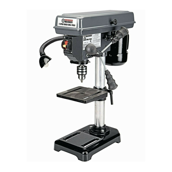
Summary of Contents for Central Machinery Central Machinery 5 Speed Bench Drill Press with Work Light
-
Page 2: Important Safety Information
Table of Contents Safety ............2 Maintenance ..........12 Specifications ..........6 Parts List and Diagram ......14 Setup ............6 Warranty ............ 16 Operation ............ 8 WARNING SYMBOLS AND DEFINITIONS This is the safety alert symbol. It is used to alert you to potential personal injury hazards. Obey all safety messages that follow this symbol to avoid possible injury or death. -
Page 3: Extension Cord
General Tool Safety Warnings (cont.) 13. DON’T OVERREACH. Keep proper Table A: RECOMMENDED MINIMUM WIRE GAUGE footing and balance at all times. FOR EXTENSION CORDS (120 VOLT) 14. MAINTAIN TOOLS WITH CARE. Keep tools sharp EXTENSION CORD NAMEPLATE and clean for best and safest performance. Follow instructions for lubricating and changing accessories. -
Page 4: Drill Press Safety Warnings
Grounding Instructions TO PREVENT ELECTRIC SHOCK AND DEATH FROM INCORRECT GROUNDING WIRE CONNECTION READ AND FOLLOW THESE INSTRUCTIONS: 110-120 V~ Grounded Tools: Tools with Three Prong Plugs 1. In the event of a malfunction or breakdown, 6. Repair or replace damaged or worn cord immediately. grounding provides a path of least resistance for electric current to reduce the risk of electric shock. -
Page 5: Vibration Safety
If unreadable or missing, contact as those dust masks that are specially Harbor Freight Tools for a replacement. designed to filter out microscopic particles. (California Health & Safety Code § 25249.5, et seq.) 13. Avoid unintentional starting. -
Page 6: Specifications
Specifications Electrical Rating 120VAC / 60Hz / 2.4A 760, 1150, 1630, 2180, 3070 RPM Spindle Speeds 5 Speeds Table Tilt 45º left and right Swing 8" Spindle Stroke 2" 227541 Spindle Taper Chuck Capacity 1/16″ - 1/2″ (13mm) Worklight Bulb Size E14 base, 120V, 15W Setup - Before Use: Read the ENTIRE IMPORTANT SAFETY INFORMATION section at the beginning of this... -
Page 7: Table Support
Table Support 1. Loosen the Pivot Lever (51). Table Column (8) Support (52) 2. Slide the Table Support (52) over the Column (8). 3. Tighten the Pivot Lever to secure the Table Support in place. Pivot Lever (51) Figure B: Installing Table Support Headstock and Feed Handles Headstock (42) 1. -
Page 8: Table Adjustment
Operating Instructions Read the ENTIRE IMPORTANT SAFETY INFORMATION section at the beginning of this manual including all text under subheadings therein before set up or use of this product. Tool Set Up TO PREVENT SERIOUS INJURY FROM ACCIDENTAL OPERATION: Turn the Power Switch of the tool off and unplug the tool from its electrical outlet before performing any procedure in this section. -
Page 9: Changing Drill Speed
Changing Drill Speed Before changing the speeds, make sure the 3. Consult the chart below and position machine is switched OFF and UNPLUGGED. the Belt (59) on the Pulleys (16, 60) according to the desired drill speed. 1. Open the pulley cover. 4. -
Page 10: Workpiece And Work Area Set Up
Workpiece and Work Area Set Up 1. Designate a work area that is clean and well-lit. 9. FOR SMALL MATERIALS that cannot be clamped The work area must not allow access by children to the table, use a drill press vise. Make sure or pets to prevent distraction and injury. -
Page 11: General Operating Instructions
General Operating Instructions 1. Bring the drill bit down with the Feed Knob to where WARNING! If the drill bit grabs and spins the workpiece, the hole is to be drilled. do not attempt to stop the spinning with your hands. Make minor workpiece alignment adjustments. -
Page 12: Cleaning, Maintenance, And Lubrication
Maintenance and Servicing Procedures not specifically explained in this manual must be performed only by a qualified technician. TO PREVENT SERIOUS INJURY FROM ACCIDENTAL OPERATION: Turn the Power Switch of the tool off and unplug the tool from its electrical outlet before performing any procedure in this section. -
Page 13: Troubleshooting
Troubleshooting Problem Possible Causes Likely Solutions Tool will not start. 1. Cord not connected. 1. Check that cord is plugged in. 2. No power at outlet. 2. Check power at outlet. If outlet is unpowered, turn off tool and check circuit breaker. If breaker is tripped, make sure circuit is right capacity for tool and circuit has no other loads. -
Page 14: Parts List
Parts List and Diagram PLEASE READ THE FOLLOWING CAREFULLY THE MANUFACTURER AND/OR DISTRIBUTOR HAS PROVIDED THE PARTS LIST AND ASSEMBLY DIAGRAM IN THIS MANUAL AS A REFERENCE TOOL ONLY. NEITHER THE MANUFACTURER OR DISTRIBUTOR MAKES ANY REPRESENTATION OR WARRANTY OF ANY KIND TO THE BUYER THAT HE OR SHE IS QUALIFIED TO MAKE ANY REPAIRS TO THE PRODUCT, OR THAT HE OR SHE IS QUALIFIED TO REPLACE ANY PARTS OF THE PRODUCT. -
Page 15: Assembly Diagram
Assembly Diagram 33 33 Item 60238 For technical questions, please call 1-800-444-3353. Page 15... - Page 16 Limited 90 Day Warranty Harbor Freight Tools Co. makes every effort to assure that its products meet high quality and durability standards, and warrants to the original purchaser that this product is free from defects in materials and workmanship for the period of 90 days from the date of purchase.
Need help?
Do you have a question about the Central Machinery 5 Speed Bench Drill Press with Work Light and is the answer not in the manual?
Questions and answers
I own a Central Machinery 5 speed Heavy Duty Bench Drill press. Model # C112, 5/8 inch Chuck, Spindle #JT #3 these are from label on press. I think I might have purchesed way back in 1980. Any chance you can send me a manual and parts catalog ? This has been a great machine !
@Jim Bibby 1934 SW 164th Street Burien, WA 98166
Looking for a chuck key replacement for model # 60238
You can use the included chuck key or an identical replacement key for the Central Machinery 5 Speed Bench Drill Press model #60238. The manual does not list the chuck key as a separately available replacement part, so you may need to find a compatible key matching the chuck size and design.
This answer is automatically generated