Table of Contents
Advertisement
Advertisement
Table of Contents

Related Manuals for MSI MS-7504


Summary of Contents for MSI MS-7504
- Page 1 MS-7504 (V1.X) Mainboard...
-
Page 2: Copyright Notice
If a problem arises with your system and no solution can be obtained from the user’s manual, please contact your place of purchase or local distributor. Alternatively, please try the following help resources for further guidance. Visit the MSI website for FAQ, technical guide, BIOS updates, driver updates, and other information: http://support.fujitsu-siemens.com... -
Page 3: Safety Instructions
Safety Instructions Always read the safety instructions carefully. Keep this User’s Manual for future reference. Keep this equipment away from humidity. Lay this equipment on a reliable flat surface before setting it up. The openings on the enclosure are for air convection hence protects the equip- ment from overheating. -
Page 4: Fcc-B Radio Frequency Interference Statement
VOIR LA NOTICE D’INSTALLATION AVANT DE RACCORDER AU RESEAU. Micro-Star International MS-7504 This device complies with Part 15 of the FCC Rules. Operation is subject to the following two conditions: (1) this device may not cause harmful interference, and (2) this device must accept any interference received, including interference that may cause undesired operation. -
Page 5: Weee (Waste Electrical And Electronic Equipment) Statement
WEEE (Waste Electrical and Electronic Equipment) Statement... -
Page 8: Table Of Contents
CONTENTS Copyright Notice....................ii Trademarks......................ii Revision History.....................ii Technical Support....................ii Safety Instructions....................iii FCC-B Radio Frequency Interference Statement..........iv WEEE (Waste Electrical and Electronic Equipment) Statement......v Chapter 1 Getting Started.................1-1 Mainboard Specifications................1-2 Mainboard Layout...................1-4 Chapter 2 Hardware Setup................2-1 Quick Components Guide................2-2 CPU (Central Processing Unit)................2-3 Memory......................2-7 Power Supply....................2-8 Back Panel......................2-9... -
Page 9: Chapter 1 Getting Started
Getting Started Chapter 1 Getting Started Thank you for choosing the MS-7504 (V1.X) Micro- ® ATX mainboard. This mainboard is based on NVIDIA MCP73O sigle chipset for optimal system efficiency. ® Designed to fit the advanced Intel Core 2 Quad, ®... -
Page 10: Mainboard Specifications
MS-7504 Mainboard Mainboard Specifications Processor Support ® ® ® - I n t e l Core 2 Quad, Core 2 Duo, Pentium and Celeron processors in the LGA775 package. Supported FSB - up to 1333 MHz Chipset ® - NVIDIA... - Page 11 Getting Started Connectors Back Panel - 1 Coaxial S/PDIF-Out jack - 1 Optical S/PDIF-Out jack - 6 USB 2.0 ports - 1 VGA port - 1 LAN jack - 1 IEEE 1394 port - 6 flexible audio jacks On-Board Pinheaders - 2 USB 2.0 pinheaders - 1 IEEE 1394 pinheader - 1 S/PDIF-Out pinheader...
-
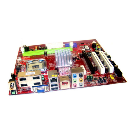
Page 12: Mainboard Layout
NVIDIA IEEE 1394 port MCP73O REALTEK Line-In RTL8211BL Line-Out T: RS-Out M: CS-Out PCI _E1 B: SS-Out REALTEK PCI _E2 ALC888S PCI 1 FINTEK VT6308P F71882FG PCI 2 BATT JAUD1 JBAT1 J1394_1 JUSB1 JUSB2 JSPD1 JFP1 MS-7504 (V1.X) Micro-ATX mainboard... -
Page 13: Chapter 2 Hardware Setup
Chapter 2 Hardware Setup This chapter tells you how to install the CPU, memory modules, and expansion cards, as well as how to setup the jumpers on the mainboard. Also, it provides the instructions on connecting the peripheral devices, such as the mouse, keyboard, etc. While doing the installation, be careful in holding the components and follow the installation procedures. -
Page 14: Quick Components Guide
MS-7504 Mainboard Quick Components Guide PWR1, CPU, CPUFAN, Memory, p.2-8 p.2-3 p.2-11 p.2-7 Back Panel, p.2-9 PWR2, p.2-8 SATA1~4, p.2-11 PCIE Slots, p.2-16 PCI Slots, p.2-16 JAUD1, SYSFAN, p.2-13 p.2-11 JUSB1~2, JSPD1, J1394_1, JBAT1, JFP1, p.2-14 p.2-12 p.2-14 p.2-15 p.2-12... -
Page 15: Cpu (Central Processing Unit)
Hardware Setup CPU (Central Processing Unit) This mainboard supports Intel ® Core 2 Quad, Core 2 Duo, Pentium ® and Celeron ® processors in the LGA775 package. When you are installing the CPU, make sure to install the cooler to prevent overheating. If you do not have the CPU cooler, consult your dealer before turning on the computer. - Page 16 MS-7504 Mainboard CPU & Cooler Installation When you are installing the CPU, make sure the CPU has a cooler attached on the top to prevent overheating. Meanwhile, do not forget to apply some thermal paste on CPU before installing the heat sink/cooler fan for better heat dispersion.
- Page 17 Hardware Setup 5. Lift the load lever up and open the 6. After confirming the CPU direction load plate. for correct mating, put down the CPU in the socket housing frame. Be sure to grasp on the edge of the CPU base. Note that the align- ment keys are matched.
- Page 18 MS-7504 Mainboard 9. Press down the load lever lightly 10. Align the holes on the mainboard onto the load plate, and then se- with the heatsink. Push down the cure the lever with the hook under cooler until its four clips get retention tab.
-
Page 19: Memory
Hardware Setup Memory These DIMM slots are used for installing memory modules. DDR2 240-pin, 1.8V 64x2=128 pin 56x2=112 pin Installing Memory Modules 1. The memory module has only one notch on the center and will only fit in the right orientation. -
Page 20: Power Supply
MS-7504 Mainboard Power Supply ATX 24-Pin Power Connector: PWR2 pin 13 This connector allows you to connect an ATX 24-pin power supply. To connect the ATX 24-pin power supply, make sure the plug of the power supply is inserted in thae proper orientation and the pins are aligned. -
Page 21: Back Panel
Hardware Setup Back Panel USB ports Coaxial S/PDIF LAN jack IEEE 1394 -Out jack Line-In RS-Out port Line-Out CS-Out SS-Out Optical S/PDIF-Out jack VGA port USB ports Coaxial S/PDIF-Out jack This SPDIF (Sony & Philips Digital Interconnect Format) connector is provided for digital audio transmission to external speakers through a coaxial cable. - Page 22 MS-7504 Mainboard Audio Ports These audio connectors are used for audio devices. You can differentiate the color of the audio jacks for different audio sound effects. Line-In (Blue) - Line In is used for external CD player, tapeplayer or other audio devices.
-
Page 23: Connectors
Hardware Setup Connectors Serial ATA Connector: SATA1/ SATA2/ SATA3/ SATA4 This connector is a high-speed Serial ATA interface port. Each connector can con- nect to one Serial ATA device. SATA4 SATA2 SATA3 SATA1 Important Please do not fold the Serial ATA cable into 90-degree angle. Otherwise, data loss may occur during transmission. - Page 24 MS-7504 Mainboard S/PDIF-Out Connector: JSPD1 This connector is used to connect S/PDIF (Sony & Philips Digital Interconnect Format) interface for digital audio transmission. SPDIF JSPD1 Front Panel Connectors: JFP1 This connector is for electrical connection to the front panel switches and LEDs. The ®...
- Page 25 Hardware Setup Front Panel Audio Connector: JAUD1 This connector allows you to connect the front panel audio and is compliant with Intel ® Front Panel I/O Connectivity Design Guide. JAUD1 Pin Definition SIGNAL DESCRIPTION MIC_L Microphone - Left channel Ground MIC_R Microphone - Right channel PRESENCE#...
- Page 26 MS-7504 Mainboard Front USB Connector: JUSB1, JUSB2 ® This connector, compliant with Intel I/O Connectivity Design Guide, is ideal for con- necting high-speed USB interface peripherals such as USB HDD, digital cameras, MP3 players, printers, modems and the like. Pin Definition...
-
Page 27: Jumpers
Hardware Setup Jumpers Clear CMOS Jumper: JBAT1 There is a CMOS RAM onboard that has a power supply from an external battery to keep the data of system configuration. With the CMOS RAM, the system can auto- matically boot OS every time it is turned on. If you want to clear the system configu- ration, set the jumper to clear data. -
Page 28: Slots
MS-7504 Mainboard Slots PCI (Peripheral Component Interconnect) Express Slots The PCI Express slot supports the PCI Express interface expansion card. The PCI Express x 16 supports up to 4.0 GB/s transfer rate. The PCI Express x 1 supports up to 250 MB/s transfer rate. -
Page 29: Chapter 3 Bios Setup
BIOS Setup Chapter 3 BIOS Setup This chapter provides information on the BIOS Setup program and allows you to configure the system for optimum use. You may need to run the Setup program when: An error message appears on the screen during the system booting up, and requests you to run SETUP. -
Page 30: Entering Setup
MS-7504 Mainboard Entering Setup Power on the computer and the system will start POST (Power On Self Test) pro- cess. When the message below appears on the screen, press <DEL> key to enter Setup. Press DEL to enter SETUP If the message disappears before you respond and you still wish to enter Setup, restart the system by turning it OFF and On or pressing the RESET button. -
Page 31: Control Keys
BIOS Setup Control Keys <↑> Move to the previous item <↓> Move to the next item <←> Move to the item in the left hand <→> Move to the item in the right hand Select the item <Enter> Jumps to the Exit menu or returns to the main menu from a <Esc>... -
Page 32: The Main Menu
MS-7504 Mainboard The Main Menu Standard CMOS Features Use this menu for basic system configurations, such as time, date etc. Advanced BIOS Features Use this menu to setup the items of AMI ® special enhanced features. Integrated Peripherals Use this menu to specify your settings for integrated peripherals. - Page 33 BIOS Setup Load Fail-Safe Defaults Use this menu to load the default values set by the BIOS vendor for stable system performance. Load Optimized Defaults Use this menu to load the default values set by the mainboard manufacturer specifi- cally for optimal performance of the mainboard. Set Supervisor Password Use this menu to set the supervisor password for BIOS.
-
Page 34: Standard Cmos Features
MS-7504 Mainboard Standard CMOS Features Date (MM:DD:YY) This allows you to set the system to the date that you want (usually the current date). The format is <day><month> <date> <year>. Day of the week, from Sun to Sat, determined by BIOS. Read- only. - Page 35 BIOS Setup Device/ Vendor/ Size/ LBA Mode/ Block Mode/ PIO Mode/ Async DMA/ Ultra DMA/ S.M.A.R.T. These will be showing the device information that you connected to the IDE/ SATA connector. Read-only. LBA/Large Mode This allows you to enable or disable the LBA Mode. Setting to Auto enables LBA mode if the device supports it and the devices is not already formatted with LBA mode disabled.
- Page 36 MS-7504 Mainboard Halt On The setting determines whether the system will stop if an error is detected at boot. When the system stops for the errors preset, it will halt on for 15 seconds and then automatically resume its operation. Available options are: [All Errors] The system stops when any error is detected.
-
Page 37: Advanced Bios Features
BIOS Setup Advanced BIOS Features Boot Sector Protection This function protects the BIOS from accidental corruption by unauthorized users or computer viruses. When enabled, the BIOS’ data cannot be changed when attempt- ing to update the BIOS with a Flash utility. To successfully update the BIOS, you’ll need to disable this Flash BIOS Protection function.You should enable this function at all times. - Page 38 MS-7504 Mainboard Boot Up Num-Lock LED This setting is to set the Num Lock status when the system is powered on. Setting to [On] will turn on the Num Lock key when the system is powered on. Setting to [Off] will allow users to use the arrow keys on the numeric keypad.
- Page 39 BIOS Setup HPET The HPET (High Precision Event Timers) is a component that is part of the chipset. You can to enable it, and will provide you with the means to get to it via the various ACPI methods. OnChip & PCIe VGA selection This item allows you to select OnChip or PCI Express VGA display.
-
Page 40: Integrated Peripherals
MS-7504 Mainboard Integrated Peripherals USB Controller This setting allows you to enable/ disable the onboard USB controller. USB Device Legacy Support Select [Enabled] if you need to use a USB-interfaced device in the operating system. Onboard LAN Controller This item is used to enable/ disable the onboard LAN controller. - Page 41 BIOS Setup On-Chip SATA Controller This item allows you to enable/ disable the SATA controller. RAID mode This item is used to enable/ disable the RAID function for SATA devices. 3-13...
-
Page 42: Power Management Setup
MS-7504 Mainboard Power Management Setup Important S3-related functions described in this section are available only when your BIOS supports S3 sleep mode. ACPI Function This item is to activate the ACPI (Advanced Configuration and Power Management Interface) Function. If your operating system is ACPI-aware, such as Windows 2000/ XP, select [Enabled]. - Page 43 BIOS Setup ACPI Standby State This item specifies the power saving modes for ACPI function. If your operating system supports ACPI, such as Windows 2000/ XP , you can choose to enter the Standby mode in S1 or S3 fashion through the setting of this field. Settings are: [S1] The S1 sleep mode is a low power state.
- Page 44 MS-7504 Mainboard Resume By PCI Device (PME#) When set to [Enabled], the feature allows your system to be awakened from the power saving modes through any event on PME (Power Management Event). Resume By PCI-E Device When set to [Enabled], the feature allows your system to be awakened from the power saving modes through any event on PCIE device.
-
Page 45: Pnp/Pci Configurations
BIOS Setup PnP/PCI Configurations Primary Graphic’s Adapter This setting specifies which graphics card is your primary graphics adapter. PCI Latency Timer This item controls how long each PCI device can hold the bus before another takes over. When set to higher values, every PCI device can conduct transactions for a longer time and thus improve the effective PCI bandwidth. - Page 46 MS-7504 Mainboard IRQ 3/ 4/ 5/ 7/ 9/ 10/ 11/ 14/ 15 These items specify the bus where the specified IRQ line is used. The settings determine if AMI BIOS should remove an IRQ from the pool of available IRQs passed to devices that are configurable by the system BIOS.
-
Page 47: H/W Monitor
BIOS Setup H/W Monitor CPU Smart FAN Control The mainboard provides the Smart Fan function which can control the CPU fan speed automatically depending on the current temperature to keep it with in a specific range. You can select a fan target value here. If the current CPU fan temperature reaches to the target value, the smart fan function will be activated. -
Page 48: Frequency/Voltage Control
MS-7504 Mainboard Frequency/Voltage Control Important Change these settings only if you are familiar with the chipset. Current CPU/ FSB/ DRAM Frequency These items show the current clocks of CPU and Memory speed. Read-only. Intel EIST The Enhanced Intel SpeedStep technology allows you to set the performance level of the microprocessor whether the computer is running on battery or AC power. - Page 49 BIOS Setup DDR Memory Timing By SPD Setting to [Enabled] enables DRAM CAS# Latency automatically to be determined by BIOS based on the configurations on the SPD (Serial Presence Detect) EEP ROM on the DRAM module. Spread Spectrum When the motherboard’s clock generator pulses, the extreme values (spikes) of the pulses create EMI (Electromagnetic Interference).
-
Page 50: Load Fail-Safe/ Optimized Defaults
MS-7504 Mainboard Load Fail-Safe/ Optimized Defaults The two options on the main menu allow users to restore all of the BIOS settings to the default Fail-Safe or Optimized values. The Optimized Defaults are the default values set by the mainboard manufacturer specifically for optimal performance of the mainboard.
Need help?
Do you have a question about the MS-7504 and is the answer not in the manual?
Questions and answers