Panasonic PT-D9510E Operating Instructions Manual
Dlp based projector
Hide thumbs
Also See for PT-D9510E:
- Operating instructions manual (41 pages) ,
- Operating instructions manual (41 pages)
Table of Contents
Advertisement
Quick Links
DLP™ based Projector Commercial Use
POWE R
SYSTEM
SELECT OR
STD
PROJ ECTO
RGB
R
INPUT 1
INPUT 2
INPUT 3
+
BRIG HT
MENU
CONT RAST
LENS
ENTE R
–
1
2
3
PC-
MUTE
4
5
6
ON
SCREE N
7
8
9
NEXT
ID SELE CT
ID ALL
0
Operating Instructions
Bedienungsanleitung
Read these instructions completely before operating this unit.
Operating Instructions
Models No.
PT-D9510E
PT-D9610E
1-94
95-187
TQBJ0085
Advertisement
Table of Contents

Related Manuals for Panasonic PT-D9510E


Summary of Contents for Panasonic PT-D9510E
-
Page 1: Operating Instructions
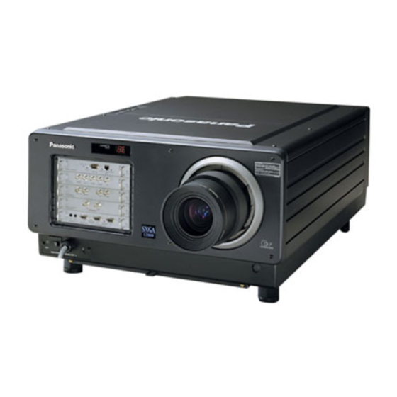
DLP™ based Projector Commercial Use Operating Instructions PT-D9510E Models No. PT-D9610E POWE R SYSTEM SELECT OR PROJ ECTO INPUT 1 INPUT 2 INPUT 3 BRIG HT MENU CONT RAST LENS ENTE R – MUTE SCREE N NEXT ID SELE CT... -
Page 2: Table Of Contents
This instruction booklet provides all the necessary operating information that you might require. We hope it will help you to get the most performance out of your new product, and that you will be pleased with your Panasonic based projector. -
Page 3: Product Outline
20 MHz to 162 MHz, computer images with signal resolutions of up to 1 600 x 1 200 dots can also be input. However, if the display resolution is greater than 1 024 x 768 dots(for the PT-D9510E)/... -
Page 4: Trademark Acknowledgements
5:4(PT-D9610E) can be projected, depending on the projection distance. When using the fixed focus lens, the available picture size is from 2,5 m (100 inches) to 4.5 m (180 inches) diagonal for the PT-D9510E,and from 2,5 m (100 inches) to 5 m (200 inches) diagonal for the PT-D9610E. -
Page 5: Important Safety Notice
IMPORTANT SAFETY NOTICE WARNING: THIS APPARATUS MUST BE EARTHED. WARNING: To prevent damage which may result in fire or shock hazard, do not expose this appliance to rain or moisture. WARNING: To prevent electric shock, do not remove cover. No user serviceable parts inside. Refer servicing to qualified service personnel. -
Page 6: Precautions With Regards To Safety
Precautions with regards to safety Read these operating instructions thoroughly and check all necessary safety precautions when setting up the projector in order to avoid accidents. WARNING Setting-up Installation should only be carried out by a qualified technician. • In order to maintain full safety and precision during installation, such work should only be carried out by a qualified technician. - Page 7 When using the projector Do not look into the lens while the projector is being used. • Strong light is emitted from the projector‘s lens. If you look directly into this light, it can hurt and damage your eyes. Do not place the projector on top of surfaces which are sloped or unstable. •...
-
Page 8: Precautions On Handling
Precautions on handling CAUTION Setting-up The following points should always be observed when setting up this projector. A dedicated power supply must be used. • Ask the place of purchase to carry out any electrical work which may be required to provide a 14 A, 200 V–240 V AC (single phase) power supply for the projector alone to use. -
Page 9: Notes On Use
Notes on use In order to get the best picture quality • If outside light or light from indoor lamps is shining onto the screen, the images projected will not have good contrast. Draw curtains or blinds over any windows, turn off any fluorescent lights near the screen and cover any highly-reflective floor and wall surfaces with carpet or wallpaper to prevent reflection. -
Page 10: Name And Function Of Each Part
Name and function of each part Projector INPUT button POWER This button is used to change the input between POWER button INPUT 1 / INPUT 2 / INPUT 3. This button is used to turn the projector INPUT If there are several input terminals in a single power supply on and off. -
Page 11: Name And Function Of Each Remote Control Part
Name and function of each remote control part Remote control unit STD (standard) button This button is used to reset all of the projector adjustment values (BRIGHT, CONTRAST, COLOUR, TINT and SHARPNESS) to the default levels which were set at the time of shipment from the factory. It is pressed after the respective adjustment mode screen has been displayed. -
Page 12: Remote Control Unit
Name and function of each remote control part (continued) Remote control unit Transmitter This emits the infrared signals which are used to control the projector when the remote control unit is being used as a wireless unit. SYSTEM POWER SELECTOR PROJECTOR Wired remote control terminal INPUT 1... -
Page 13: Before Using The Remote Control Unit
Before using the remote control unit Inserting the batteries Insert the AA batteries supplied with the remote control unit, making sure that the polarities are correct. The batteries also need to be inserted when the remote control unit is connected to the projector using the remote control cable. -
Page 14: Using The Remote Control Unit With The Cable
Using the remote control unit with the cable The remote control unit can be connected to the projector using the accessory remote control cable. [Projector] This cable should be connected to the REMOTE IN2 IN terminal at the front of the projector and to the remote control cable terminal. -
Page 15: Turning The Power On And Off
Turning the power ON and OFF Always be sure to follow the procedure given below to turn the projector power on and off. Turning the power on Turning the power off Main power ON (The power indicator will become red) While projecting a picture Press the [ ] side of the MAIN POWER switch at (The power indicator is green) -
Page 16: On-Screen Menu Operation Guide
On-screen menu operation guide The figure below shows on-screen displays for any desired setting, starting with the MAIN MENU, and ending with its sub-menu. •[On-screen displays such as the input signal type will appear when the input Normal screen signal is changed. (The display will LENS (Lens adjustment mode) disappear automatically.)] PICTURE (Picture adjustment mode) -
Page 17: Before Using The Projector
Before using the projector The projection lenses and input modules which are available for use with this projector need to be purchased separately , and must be installed to the projector before the projector can be used. • Obtain the required projection lenses and input modules beforehand in accordance with the projection NOTE distance and the system used. -
Page 18: Setting Up The Projector
Setting up the projector • After determining the installation position of the projector and screen in consideration of the audience positions, install them according to the chapter "Projection distance for each projection lens (sold separately)" on pages 20 - 23. Installing to the floor (Including the direct rear-mounting) 1. - Page 19 Installing to the ceiling (Including direct rear-projection) • Using the projector by installing to the ceiling requires an optional ceiling mount bracket (ET-PKD95). For the projection distance (L), refer to the chapter "Projection distance for each projection lens (sold separately)" on pages 20 - 23.
-
Page 20: Projection Distance For Each Projection Lens (Sold Separately)
Screen : Projection distance SH : Effective height of screen Projection distance measurements for PT-D9510E (screen aspect ratio: 4:3) unit: mm (feet/inches) Projection distance Picture Screen size... - Page 21 Projection distance measurements for PT-D9510E (screen aspect ratio: 16:9) unit: mm (feet/inches) Projection distance Picture Screen size Zoom lens size Effective Effective height(SH) width(SW) Min. Max. Min. Max. Min. Max. NOTE: • The projection distance listed in the table may have a variation within ± 5 %.
- Page 22 Projection distance measurements for PT-D9610E (screen aspect ratio: 5:4) unit: mm (feet/inches) Projection distance Picture Screen size Zoom lens size Effective Effective Min. Min. height(SH) width(SW) Max. Max. Max. Min. Min. Max. Projection distance measurements for PT-D9610E(screen aspect ratio: 16:9) unit: mm (feet/inches) Projection distance Picture...
- Page 23 Calculation of the projection distance for each projection lens (for PT-D9510E) If there is no reference made to the require picture size, calculate the projection distance using an expression below after obtaining the diagonal measurement (inch) of the screen you will use.
-
Page 24: Adjusting Projector Feet
Adjusting projector feet The four feet on the bottom of the projector are adjustable for the height ( 0 mm/0" to 25 mm/1") and can be used for its adjustment when the installation position is not level. [ Side view ] [ Front view ] Adjustable feet... -
Page 25: Setting The Projection Method
Setting the projection method The projection method can be set in accordance with the way the projector has been installed. If the projected picture is upside-down or back-to-front, change the projection method while referring to illustrations A to D below. A : Front-floor projection (FRONT-F) B : Rear-ceiling projection (REAR-C) C : Rear-floor projection (REAR-F) -
Page 26: Adjusting The Lens
Adjusting the lens Adjusting the focus Adjustment procedure Press the LENS button..The LENS screen will be displayed. Use the control level buttons ( and ) to adjust the focus to the correct setting. • Initial pressing of these buttons will allow fine adjustment. Pressing and holding these buttons will allow the slow mode for the first six seconds and then the fast mode. - Page 27 Adjustment range after lens position (optical shift) Adjustment range after lens positioning is as follows: The numbers in brackets are the dimensions when the ET-D95LE9 lens is being used. Floor projection for PT-D9510E Floor projection for PT-D9610E (0.24H) (0.24H) 0.31H 0.31H...
-
Page 28: Installing The Input Module
Installing the input module Obtain the required input modules (sold separately) beforehand in accordance with the system input signal. • Types of input module (sold separately) Input signal level Input signal Module No. Video/Sync. signal input impedance : 75 /1 k Cr, B/P : 0.7 V [p-p] or 1.0 V [p-p] with BETACAM input... - Page 29 Installing the input modules Disconnect the power supply from the projector before installing any of the input modules. Installation procedure Remove the two screws which are holding the slot cover where the input module is to be installed, and then remove the slot cover.
-
Page 30: Connecting The Input Module Signal Source
Connecting the input module signal source When setting up the projector, you will need to connect the signal source to an input module according to the type of signal being input. Projector Personal computer VGA to BNC adapter cable RGB signal RGB signal input module ET-MD95RGB High-definition VCR... - Page 31 Connecting the signal source to the input module for analogue RGB signals If using the input module for analogue RGB signals in order to connect the projector to a personal computer, you will also need to use a separate interface (D-SUB BNC) cable.
- Page 32 Horizontal scanning frequency(kHz) Vertical scanning frequency(Hz) Note: • The display resolution of this projector is 1 024 x 768 dots(PT-D9510E)/1 280 x 1 024 dots(PT- D9610E) If the display resolution indicated in the above data exceeds this resolution, the resolution will...
- Page 33 Connecting the signal source to the input module for video signals 1.Connecting a video signal source Video signal input module (sold separately) ET-MD95VM2 LINE OUT LINE/Cr IN Y IN Video Module ET-MD95VM2 Video signal Luminance signal Colour signal S terminal BNC (Purchase an S-VIDEO- Monitor TV Video signal...
- Page 34 Connecting the signal source to the input module for video signals 2.Connecting a component signal source Video signal input module (sold separately) ET-MD95VM2 LINE OUT LINE/Cr IN Y IN Video Module ET-MD95VM2 Luminance signal Y Colour difference Colour difference signal C signal C DVD player •...
- Page 35 • Before connecting the cable, check to make sure that the projector and PC are turned off. If cable connection is attempted with the projector and/or PC turned on, the PC may be damaged. • Concerning a connecting cable used for this module, because its characteristic impedance can affect the picture performance, consult a Panasonic sales company.
- Page 36 Connecting the signal source to the input module for serial digital signals Serial digital input module(sold separately) ET-MD95SD1 (for 480i/576i) 480i Module SERIAL ET-MD95SD1 SD signal output SD signal Professional-type digital VCR • Use an input module which correctly matches the input signal type. •...
- Page 37 Connecting the signal source to the input module for serial digital signals 1. 480p dual link (4:2:2p): 59.94 Hz progressive scan with 720 by 483 active lines at 270 Mbps, complying with the SMPTE294M Standard Serial digital input module(sold separately) ET-MD95SD2 (for 480p/480i/576i) MAIN IN MAIN OUT...
- Page 38 Connecting the signal source to the input module for serial digital signals 2. 1) 480p single link (4:2:0p): 59.94 Hz progressive scan with 720 by 483 active lines at 360 Mbps, complying with the SMPTE294M Standard 2) 480i (4:2:2): 59.94 Hz interlace scan with 525 lines at 270 Mbps, complying with the SMPTE294M Standard 3) 576i (4:2:2): 50 Hz interlace scan with 625 lines at 270 Mbps, complying with the SMPTE294M Standard...
- Page 39 Connecting the signal source to the input module for serial digital signals Serial digital input module(sold separately) ET-MD95SD3 (for HD SDI) 1080i/720p Module HD SERIAL ET-MD95SD3 HD SD signal SD signal output (Active through) Professional-type digital VCR • Use an input module which correctly matches the input signal type. •...
-
Page 40: Selecting The Input Signal / Selecting The System Format
Selecting the input signal • The following remote control unit buttons and the INPUT button on the projector operating panel can be used to switch between different input sources. R G B : Invalid Remote control unit INPUT 2 R G B INPUT 1 INPUT 3 INPUT 1... -
Page 41: Selecting The Signal Of Et-Md95Vm2
Selecting the signal of ET-MD95VM2(sold separately) When using the projector with the optional ET-MD95VM2 Video Input Module, select the appropriate video signal format that matches the video equipment you are using. Setting procedure Press the MENU button..The MENU screen will be displayed. Press the UP ( ) and DOWN ( ) arrow buttons to select OPTION. -
Page 42: Registering Input Signal Data
Registering input signal data Because the projector has no factory pre-set data of input signals, be sure to register input signal data before first use. NOTE • Up to 64 different input signals can be registered. • Input a signal according to an input module installed on the projector and register the signal data. Registration new signal •... - Page 43 When the memory does not allow new signal registration because it is full • When a total of 64 signals has already been registered and the memory is full, inputting a new signal and pressing the MENU button on the remote control unit or the projector operating panel will display the overwriting registration screen below.
- Page 44 Sub-memory This equipment has a sub memory function which enables storage of multiple image adjustment data sets, even when the signal is determined to be the same due to the frequency and form of the synchronization signal source. Use this when image adjustment (like aspect switching or white balance) is necessary due to the same signal source.
- Page 45 On-screen display Input switching/Signal switching This displays the stored signal name for the STATUS screen during signal switching. Stored signal details A name can be entered for each sub-memory. MEMORY-No:A5-2 Address No. (A1,A2,..H7,H8) Displays sub-memory number(1-9) Location where signal is stored 1 is the basic signal.
-
Page 46: Using The Rgb Reality Mode
Using the RGB REALITY mode The RGB REALITY mode is a mode for converting RGB (primary color) input signals to component signals, performing high picture quality playback using image conversion processing specially for moving pictures. You can choose the RGB mode best suited for the type of RGB signals you are using (refer to page 40): RGB mode: Choose this mode when the RGB signal source is a PC or other computer-based device that focuses on still images. -
Page 47: Adjusting The Picture Automatically
Adjusting the picture automatically The automatic adjustment (AUTO SETUP) is a function to automatically adjust the resolution, clock phase, and picture position when inputting an analogue RGB signal consisting of dots like a computer signal. (The input of a moving picture signal or any signal other than analogue RGB signals cannot enable this function.) It is recommendable for the automatic adjustment to input a picture signal including a brighter white box around the outside of the perimeter of a basic picture with clear, black-and-white characters and not including a halftone like a photograph or CG. - Page 48 2. Special signal automatic adjustment Adjustment procedure Press the MENU button..The MENU screen will be displayed. Press the LEFT ( ) arrow buttons once time. ) or RIGHT( ... The AUTO SETUP MENU screen will be displayed. Press the LEFT ( ) arrow to switch to desired MODE.
-
Page 49: Adjusting The Picture Manually
Adjusting the picture manually Signals which cannot be adjusted automatically should be adjusted manually. The following settings can be adjusted manually, and the respective adjustment procedures are given below. 1.Input signal resolution data 2.Clock phase 3.Picture position Adjusting the input signal resolution Adjustment procedure Press the MENU button. - Page 50 Adjusting the clock phase If a flicker or bleeding of the contour appears on the screen, adjust the clock phase to obtain an optimum picture. Adjustment procedure Press the MENU button..The MENU screen will be displayed. Press the UP ( ) and DOWN ( ) arrow buttons to select POSITION.
-
Page 51: Adjusting The Picture Position
Adjusting the picture position Adjustment procedure Press the MENU button..The MENU screen will be displayed. Press the UP ( ) and DOWN ( ) arrow buttons to select POSITION. Press the ENTER button..The POSITION screen will be displayed. Press the UP ( ) and DOWN ( ) arrow buttons to select SHIFT. -
Page 52: Adjusting The Blanking
Adjusting the blanking If picture noise appears at the perimeter of the screen or a picture extends off the screen a little, adjust the blanking to fine-tune the screen. Adjustment procedure Press the MENU button..The MENU screen will be displayed. Press the UP ( ) and DOWN ( ) arrow buttons to select POSITION. -
Page 53: Adjusting The Clamp Position / Picture Mute Function
Adjusting the clamp position • If the black portions of the picture are fractured or tinged with green, adjust the clamp position its optimum state. Adjustment procedure Press the MENU button..The MENU screen will be displayed. Press the UP ( ) and DOWN ( ) arrow buttons to select POSITION. -
Page 54: Adjusting The Keystone(Trapezoidal Distortion)
Adjusting the keystone(Trapezoidal distortion) • The KEYSTONE adjustment allows you to compensate for pictures’ horizontal trapezoidal distortion. (Keystone adjustment can not carried out in built-in test pattern.) Adjustment procedure Press the MENU button..The MENU screen will be displayed. Press the UP ( ) and DOWN ( ) arrow buttons to select POSITION. -
Page 55: Adjusting The Picture To The Desired Setting
Adjusting the picture to the desired setting The following procedures can be used to adjust the picture to the desire appearance. Adjustment procedure ... Adjusting the COLOUR setting Press the MENU button..The MENU screen will be displayed. Press the UP ( ) and DOWN ( ) arrow buttons to select PICTURE. -
Page 56: Adjusting The White Balance
Adjusting the white balance Adjustment procedure (Project a signal to be adjusted) Press the MENU button..The MENU screen will be displayed. Press the UP ( ) and DOWN ( ) arrow buttons to select PICTURE. Press the ENTER button..The PICTURE screen will be displayed. Press the UP ( ) and DOWN ( ) arrow buttons to select COLOR TEMP. -
Page 57: Adjusting The Picture Quality
Adjusting the picture quality The following procedures can be used to adjust the picture quality to the desired setting. Adjustment procedure Press the MENU button..The MENU screen will be displayed. Press the UP ( ) and DOWN ( ) arrow buttons to select PICTURE. - Page 58 • NR (noise reduction) settings cannot be adjusted for analogue RGB input and TMDS input. • The FILTER adjustment is ineffective for XGA (1 024 x 768) mode on the PT-D9510E, or SXGA (1 280 x 1 024) mode on the PT-D9610E. It is also ineffective for any video input mode other than analogue RGB and TMDS modes, or if “THROUGH”...
- Page 59 5:4(for the PT-D9610E), the left and right edges of the picture are cropped. HV-Fit The input signal is converted to an aspect ratio of 4:3(for the PT-D9510E) / 5:4(for the PT-D9610E). For signals with an aspect ratio other than 4:3(for the PT-D9510E) / 5:4(for the PT-D9610E), circles in the picture become distorted, etc.
- Page 60 Screen examples for different size settings (For PT-D9510E) INPUT PICTURE 640 400 1152 864 1280 1024 SIZE SETTING Default The picture is displayed at maximum size while maintaining the original aspect. Through H-Fit V-Fit HV-Fit * If the picture extends outside the screen, the top-left corner is used as the reference point.
- Page 61 Screen examples for different size settings(For PT-D9610E) INPUT PICTURE 640 400 1152 864 1280 1024 SIZE SETTING Default The picture is displayed at maximum size while maintaining the original aspect. Through H-Fit V-Fit HV-Fit * If the picture extends outside the screen, the top-left corner is used as the reference point.
-
Page 62: Power Up Function
Power up function Power up function The projector is provided with a power up function which allows the performance of the lamp to be utilized to the maximum level. Press the MENU button..The MENU screen will be displayed. Press the UP ( ) and DOWN ( ) arrow buttons to select OPTION. -
Page 63: Contrast Switching Function
Contrast switching function This equipment has 3 mode types for adjusting to the use environment. Switching procedure Press the MENU button..The MENU screen will be displayed. Press the UP ( ) and DOWN ( ) arrow buttons to select OPTION. Press the ENTER button. -
Page 64: When Inputting Betacam With Yc B Cr 480I
When inputting BETACAM with YC Cr 480i When receiving 480i with analog component signal YCbCr input, it is possible to switch Cb, Cr input. Switching procedure Press the MENU button..The MENU screen will be displayed. Press the UP ( ) and DOWN ( ) arrow buttons to select PICTURE. -
Page 65: Displaying A Test Pattern
Displaying a test pattern 17 types of test pattern are built in. These test patterns can be used to check the various adjustment settings. Use the following procedure to display a test pattern. NOTE •These test patterns cannot reflect the adjustment results of various picture settings such as picture quality, positions, and sizes. -
Page 66: Displaying The Projector Settings
Displaying the projector settings Display procedure Press the MENU button..The MENU screen will be displayed. Press the UP ( ) and DOWN ( ) arrow buttons to select OPTION. Press the ENTER button..The OPTION screen will be displayed. Press the UP ( ) and DOWN ( ) arrow buttons to select SYSTEM... -
Page 67: Adjusting The Edge Blending
Adjusting the edge blending The projector is equipped with a function to blend edges that may appear on the screen during multi-screen use. Adjustment procedure Press the MENU button..The MENU screen will be displayed. Press the UP ( ) and DOWN ( ) arrow buttons to select POSITION. -
Page 68: Adjusting The Color Matching
Adjusting the color matching The projector is equipped with color matching adjustment functions to adjust colour balance when using several units in combination. Adjustment procedure Press the MENU button..The MENU screen will be displayed. Press the UP ( ) and DOWN ( ) arrow buttons to select PICTURE. -
Page 69: Setting And Specifying Id Numbers
Setting and specifying ID numbers This projector is provided with an ID number function, so that if multiple projectors are being used together, the projectors can be controlled all at once or separately using a single remote control unit. Because the factory pre-setting of the ID number is ALL, using only one projector do not require this setting. Setting ID numbers Setting procedure Press the MENU button. - Page 70 Setting remote control unit ID numbers When an ID number has been assigned for a projector, you then need to assign the same ID number as the projectors to be controlled to the remote control unit which is to be used to operate these projectors, otherwise the remote control unit cannot be used.
-
Page 71: Using The Rs-232C Connectors
Using the RS-232C connectors The projector is equipped with a D-SUB 9-pin RS-232C input connector and RS-232C output connector which allow the projector to be controlled externally. These connectors conform to RS-232C specifications, and can be used by a computer which conforms to either RS-232 or RS-232C specifications. •... - Page 72 ID List Code specified Code specified Code specified Code specified Code specified Code specified Example: Send a INPUT 1 command to the DLP based projector with ID1. Receive (PC based projector) STX(02h) ID NO (01h) INPUT 1(0Ah) ETX(03h) Send (PC based projector) STX(02h) ID NO (01h)
-
Page 73: Setting Procedure
RS-232C settings Setting procedure Press the MENU button..The MENU screen will be displayed. Press the UP ( ) and DOWN ( ) arrow buttons to select OPTION. Press the ENTER button..The OPTION screen will be displayed. Press the UP ( ) and DOWN ( ) arrow buttons to select RS-232C SETTING. - Page 74 List of basic control commands Target remote control buttons CODE NAME INPUT1 INPUT2 INPUT3 NEXT BRIGHT CONTRAST POWER POWER ON POWER OFF *2 TEST *2 ON SCREEN ID ALL *1 ID SELECT *1 INPUT *2 SYSTEM SELECTOR ENTER MENU LENS PICTURE MUTE NOTE *1: This command is for the supplied remote control.
-
Page 75: Selecting The Rs-422 Serial Interface
Selecting the RS-422 Serial Interface Converting the RS-232C-IN port into an RS-422-IN port If the projector power is ON, turn it OFF by pressing the remote-control (or on the projector) POWER key, and wait for approximately 5 minutes until the cooling fan stops. Set the front MAIN POWER switch of the projector to OFF, then unplug the projector from the supply outlet. - Page 76 Selecting the RS-422 Serial Interface (continued) Converting the RS-232C-OUT port into an RS-422-OUT port If the projector power is ON, turn it OFF by pressing the remote-control (or on the projector) POWER key, and wait for approximately 5 minutes until the cooling fan stops. Set the front MAIN POWER switch of the projector to OFF, then unplug the projector from the supply outlet.
-
Page 77: Using The Network Module
Using the network module The network module for this unit has a LAN interface, so the unit can be controlled from the web browser of a PC. The network module has an automatic send function for e-mail. Mail can be sent to a previously set e-mail address when a problem occurs, or when the set value for the lamp usage time is attained. -
Page 78: Initial Setting Of Network Module
Initial setting of network module Operating procedure Press the MENU button..The MENU screen will be displayed. Press the UP ( ) and DOWN ( ) arrow buttons to select OPTION. Press the ENTER button..The OPTION screen will be displayed. Press the UP ( ) and DOWN ( ) arrow buttons to select NETWORK... - Page 79 Item Description Function Host name display and setting HOSTNAME Change if necessary when using a DHCP server etc. DHCP client function DHCP Turn the DHCP item ON when automatically obtaining IP addresses using a DHCP server. Turn it OFF when not using a DHCP server.
- Page 80 Go to: 192.168.0.8 Input the IP address set on the unit in the URL input field of the web browser. Input user1 in the user name field, and input panasonic (lower case letters) in the password field. Username and Password Required Enter username for Panasonic Projector Control at 192.168.0.8...
- Page 81 Top page Initial setup button If you click on this item, the page for TOP-Panasonic projector control window - Netscape changing passwords and initial setting File Edit View Window Help of the IP address is displayed. Projector control window Projector control button Clicking on this option displays the projector control page.
- Page 82 Network setting page Select ON to activate DHCP client function Input IP address when not using DHCP server Input port number. Normally, this is used with the default 80. Input net mask when not using DHCP server Input gate address when not using DHCP server Input projector name.
- Page 83 Status display page Displays input slot status Displays projector internal temperature Displays projector exhaust temperature Displays lamp illumination remaining time Displays projector operation time Displays projector type. Displays self-diagnosis Displays firmware information version of projector main unit...
- Page 84 E-mail setting page • This enables automatic sending of mail to up to two mail addresses. Data such as the set-up When using the e-mail Input the IP address of location of the projector can be function, select Enable. the e-mail server (SMTP). input so it is easy to understand where the e-mail came from.
- Page 85 E-mail setting page (continue) When using two e-mail addresses, input the e-mail address to send mail to. After all input is finished, press Select the conditions for sending e-mail Error: When an error occurs in self-diagnosis the Submit button. Warning LAMP1: When the lamp illumination remaining time reaches the time set in the column on the right side.
- Page 86 Firmware update page (Firmware updating should only be done by a person with specialized knowledge.) After inputting the file name, press Input the file name of the firmware to the upload button. Transfer will begin. be updated. It takes a few tens of seconds for transfer to occur.
-
Page 87: Cleaning The Air Filter
Returning the network module settings to the factory shipment condition The following procedure allows the user to reset all of the network module settings (such as the IP address, password and e-mail settings) to the factory shipment condition. Procedure Using the “POWER” button on the remote control, set the unit power supply to the standby state. Using an object with a pointed tip, press and hold the FUNCTION switch for 3 seconds. -
Page 88: Replacing The Lamp Unit
Xenon lamps. Notes on handling the lamp unit • The lamp unit is sold separately and consult a Panasonic authorized dealer or service center. Part No. : ET-LAD9610 Lamp unit replacement period The life span of this lamp unit is 1 500 hours maximum, after which it will need replacing (recommended replacement time is 1 000 hours). -
Page 89: Before Asking For Service
The DMD devices are produced using high-precision technology (Three sheets of approximately 780,000 pixels (for PT-D9510E)/1,310,000 pixels (for PT-D9610E)are used for the projector.), but there might be extremely small chipped or brighter points of the picture on the screen. -
Page 90: Specifications
Storage environment Temperature: 25 C – 65 C Humidity: 10 % – 80 % (with no condensation) Element size: 0.9 inches (aspect ratio ; 4:3) : PT-D9510E elements : 1.1 inches (aspect ratio ; 5:4) : PT-D9610E... - Page 91 Input With serial digital input module (sold separately) installed signals ET-MD95SD1 (for 480i/576i) SERIAL IN (SMPTE259M) BNC termination SERIAL OUT (SMPTE259M) BNC termination ET-MD95SD2 (for 480p/480i/576i) SERIAL MAIN IN/SUB IN (SMPTE259M/294M) BNC termination SERIAL MAIN OUT/SUB OUT (SMPTE259M/294M) BNC termination ET-MD95SD3 (for HD SDI) HD-SERIAL IN...
-
Page 92: Sold Separately (Optional Accessories)
Zoom lens 1.5 – 2.5 : 1 ET - D95LE1 Zoom lens 2.5 – 4.0 : 1 ET - D95LE2 PT-D9510E Zoom lens 4.0 – 7.0 : 1 ET - D95LE3 Zoom lens 1.5 – 2.0 : 1 ET - D95LE5... -
Page 93: Dimensions
Dimensions UNIT : mm (inch) 680(26.8") 753(29.6") 13(0.5") 50(2") 114(4.5") 169(6.7") 712(28") 604(23.8") 1051(41.4")
Need help?
Do you have a question about the PT-D9510E and is the answer not in the manual?
Questions and answers