Advertisement
Quick Links
Download this manual
See also:
Instructions for Using
MICROWAVE
HOOD
COMBINATION
INSTALLATION
INSTRUCTIONS
This product is suitable for use above electric or gas cooking products up to and including 30" (76.2 cm) wide. See "Installation
Requirements" section for further notes.
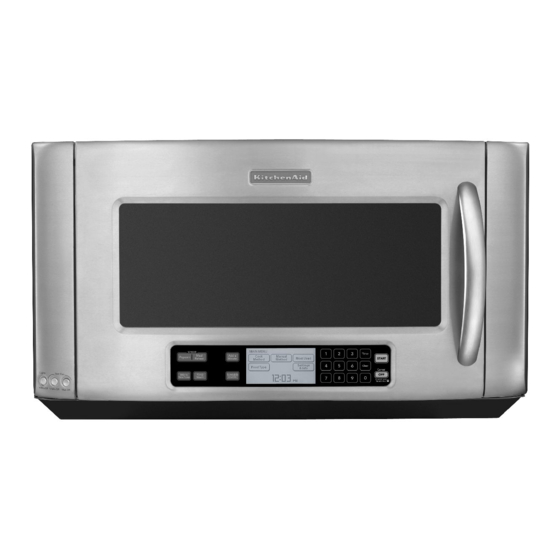
These installation instructions cover different models. The appearance of your particular model may differ slightly from the illustration in
these installation instructions.
Table of Contents
MICROWAVE HOOD COMBINATION SAFETY..............................1
INSTALLATION REQUIREMENTS................................................... 2
Tools and Parts............................................................................... 2
Location Requirements................................................................... 2
Product Dimensions ....................................................................... 3
Electrical Requirements.................................................................. 3
INSTALLATION INSTRUCTIONS..................................................... 4
Remove Mounting Plate................................................................. 4
Convert Microwave Oven to ExternalVenting ............................... 4
Locate Wall Stud(s)......................................................................... 6
Mark RearWall................................................................................ 7
Drill Holes in RearWall.................................................................... 7
Attach Mounting Plate to Wall........................................................ 8
Prepare Upper Cabinet................................................................... 8
Install the Microwave Oven ............................................................ 9
Complete Installation.................................................................... 10
VENTING DESIGN SPECIFICATIONS............................................ 1 1
ASSISTANCE ................................................................................... 12
Replacement Parts ....................................................................... 12
MICROWAVE
HOOD COMBINATION
SAFETY
Your safety and the safety of others are very important.
We have provided many important safety messages in this manual and on your appliance. Always read and obey all safety
messages.
This is the safety alert symbol.
This symbol alerts you to potential hazards that can kill or hurt you and others.
All safety messages will follow the safety alert symbol and either the word "DANGER" or "WARNING."
These words mean:
You can be killed or seriously injured if you don't immediately
follow
instructions.
You can be killed or seriously injured if you don't follow
instructions.
All safety messages will tell you what the potential hazard is, tell you how to reduce the chance of injury, and tell you what can
happen if the instructions are not followed.
W10189714A
Advertisement

Related Manuals for KitchenAid KHMS2050SSS2


Summary of Contents for KitchenAid KHMS2050SSS2
- Page 1 MICROWAVE HOOD COMBINATION INSTALLATION INSTRUCTIONS This product is suitable for use above electric or gas cooking products up to and including 30" (76.2 cm) wide. See "Installation Requirements" section for further notes. These installation instructions cover different models. The appearance of your particular model may differ slightly from the illustration in these installation instructions.
- Page 2 INSTALLATION REQUIREMENTS The microwave oven is set for recirculation installation. For external (wall or roof) venting, see "Venting Design Specifications" section. "7 .._._a_S(_ ¸_ " Check the opening where the microwave oven will be installed. Tools Needed The location must provide: Gather the required tools and parts before starting installation.
- Page 3 Installation Dimensions NOTE: The grounded 3 prong outlet must be inside the upper cabinet. See "Electrical Requirements" section. Electrical Shock Hazard Plug into a grounded 3 prong outlet. Do not remove ground prong. Do not use an adapter. Do not use an extension cord.
- Page 4 INSTALLATION INSTRUCTIONS _3_ ::,:=.._, _ _7¸ > X _ _ _ _-, _.-_ > NOTE: To avoid possible damage to the work surface, cover the :×i>g!£i]a ..{>} work surface. 1. Remove any remaining contents from the microwave oven The microwave oven is set for recirculation installation. For wail or cavity.
- Page 5 When the vent deflector is as far back as it can easily slide, flip Save the cover for possible change of venting method in the future. it so that the wide side is to the back of the microwave oven, and the narrow side (with holes) is down.
- Page 6 Leca :e Wa llt S ,ud(s} NOTE: If no wall studs exist within the cabinet opening, do not 1. Using a stud finder, locate the edges of the wall stud(s) within install the microwave oven. the opening. See illustrations in "Possible Wall Stud Configurations." 2.
- Page 7 Wall Venting Installation Only The microwave oven must be installed on a minimum of 1 wall Centerline Upper cabinet bottom stud, preferably 2, using a minimum of 1 lag screw, preferably 2. Using measuring tape, find and clearly mark the vertical centerline of the opening.
- Page 8 Wall Stud at One Corner Hole (Figure 3) NOTE: Secure themounting plate tothewall a tbothbottom With the support tabs of the mounting plate facing forward, corner holes drilled intothe wall s tuds and/or drywall using either insert a 1/4-20 x 3" round-head bolt through the corner hole 1/4-20 x 3"round-head bolts and toggle n uts or1/4x2"lag that fits over the 3/4"...
- Page 9 5. Cut the 11/2"(3.8 cm) diameter hole at the circular shaded area "G" on the template. This hole is for the power supply cord. NOTE: If upper cabinet is metal, the supply cord bushing needs to be installed around the supply cord hole, as shown. A.
- Page 10 For Roof Venting Installation Only 1. Refer to the Use and Care Guide for instructions on how to 1. Insert damper assembly through the cabinet cutout so that the install filters into your model. long tab of the damper assembly slides into the slot on the left side of the damper vent opening, as shown.
- Page 11 VENTING DESIGN SPECIFICATIONS This section is intended for architectural designer and Rectangular to Round Transition builder/contractor reference only. NOTE: The minimum 3" (7.6 cm) clearance must exist between NOTES: the top of the microwave oven and the rectangular to round transition piece so that the damper can open freely and fully.
- Page 12 Recommended Vent Length A 31/4 '' x 10" (8.3 x 25.4 cm) rectangular or 6" (15.2 cm) round vent 6" (15.2 cm) vent system = 73 ft (22.2 m) total should be used. The total length of the vent system including straight vent, elbow(s), transitions and wall or roof caps must not exceed the equivalent of 140 ft (42.7 m) for either type of vent.
Need help?
Do you have a question about the KHMS2050SSS2 and is the answer not in the manual?
Questions and answers