Lenovo ThinkPad Edge E530 Hardware Maintenance Manual
Hide thumbs
Also See for ThinkPad Edge E530:
- Benutzerhandbuch (186 pages) ,
- Felhasználói kézikönyv (180 pages) ,
- Uputstvo za korisnike (174 pages)
Table of Contents
Advertisement
Quick Links
Advertisement
Table of Contents

Related Manuals for Lenovo ThinkPad Edge E530


Summary of Contents for Lenovo ThinkPad Edge E530
- Page 1 Hardware Maintenance Manual ThinkPad Edge E530, E530c, and E535...
- Page 2 Appendix A “Notices” on page 109. Second Edition (October 2012) © Copyright Lenovo 2012. LIMITED AND RESTRICTED RIGHTS NOTICE: If data or software is delivered pursuant a General Services Administration “GSA” contract, use, reproduction, or disclosure is subject to restrictions set forth in Contract No. GS-35F-05925.
-
Page 3: Table Of Contents
Checkout guide ....Looking up FRU information ..Lenovo Solution Center ..Quick test programs... - Page 4 1050 Memory modules ... 1190 RJ45 sub card ... . 1060 Hard disk drive assembly ..1200 Optical drive sub card .
-
Page 5: About This Manual
® This manual contains service and reference information for the following ThinkPad products. ThinkPad Edge E530, E530c, and E535 Machine Type (MT) 3259, 3260, 3366, and 6272 Use this manual along with the advanced diagnostic tests to troubleshoot problems. Important: This manual is intended only for trained service technicians who are familiar with ThinkPad products. - Page 6 Hardware Maintenance Manual...
-
Page 7: Chapter 1. Safety Information
• Reinstall all covers correctly before returning the machine to the customer. • Fan louvers on the machine help to prevent overheating of internal components. Do not obstruct fan louvers or cover them with labels or stickers. © Copyright Lenovo 2012... -
Page 8: Electrical Safety
Electrical safety Observe the following rules when working on electrical equipment. Important: • Use only approved tools and test equipment. Some hand tools have handles covered with a soft material that does not insulate you when working with live electrical currents. •... -
Page 9: Safety Inspection Guide
0.1 ohm or less between the external ground pin and the frame ground. b. The power cord should be the authorized type specified for your computer. Go to: http://www.lenovo.com/serviceparts-lookup. c. Insulation must not be frayed or worn. 4. Check for cracked or bulging batteries. -
Page 10: Grounding Requirements
Notes: 1. Use product-specific ESD procedures when they exceed the requirements noted here. 2. Make sure that the ESD protective devices you use have been certified (ISO 9000) as fully effective. When handling ESD-sensitive parts: • Keep the parts in protective packages until they are inserted into the product. •... - Page 11 DANGER DANGER DANGER DANGER DANGER DANGER Chapter 1 Safety information...
- Page 12 DANGER Hardware Maintenance Manual...
- Page 13 PERIGO PERIGO PERIGO Chapter 1 Safety information...
- Page 14 PERIGO PERIGO PERIGO PERIGO PERIGO Hardware Maintenance Manual...
- Page 15 DANGER DANGER DANGER DANGER DANGER Chapter 1 Safety information...
- Page 16 DANGER DANGER DANGER VORSICHT VORSICHT Hardware Maintenance Manual...
- Page 17 VORSICHT VORSICHT VORSICHT VORSICHT VORSICHT VORSICHT Chapter 1 Safety information...
- Page 18 Hardware Maintenance Manual...
- Page 19 Chapter 1 Safety information...
- Page 20 Hardware Maintenance Manual...
- Page 21 Chapter 1 Safety information...
- Page 22 Hardware Maintenance Manual...
-
Page 23: Laser Compliance Statement (Multilingual Translations)
Laser compliance statement (multilingual translations) The laser compliance statements in this section are provided in the following languages: • English • Arabic • Brazilian Portuguese • French • German • Hebrew • Japanese • Korean • Spanish • Traditional Chinese Chapter 1 Safety information... - Page 24 Hardware Maintenance Manual...
- Page 25 Chapter 1 Safety information...
- Page 26 Hardware Maintenance Manual...
- Page 27 Chapter 1 Safety information...
- Page 28 Hardware Maintenance Manual...
-
Page 29: Chapter 2. Important Service Information
UEFI BIOS downloads. Telephone numbers for Lenovo Support are available at: http://www.lenovo.com/support/phone • System disassembly and reassembly videos that show the FRU removal or replacement procedures for the Lenovo authorized service technicians are available at: http://www.lenovoservicetraining.com/ion/ Strategy for replacing FRUs Before replacing parts: Make sure that all software fixes, drivers, and UEFI BIOS downloads are installed before you replace any FRUs listed in this manual. -
Page 30: Strategy For Replacing A Hard Disk Drive
Dynamic Configure To Order (CTO) This provides the ability for a customer to configure a Lenovo solution from an eSite, and have this configuration sent to fulfillment, where it is built and shipped directly to the customer. The machine label, Product Entitlement Warehouse (PEW), and eSupport will load these products as the 4-digit MT and 3-digit model, where model = “CTO”... -
Page 31: Fru Identification For Cto, Cmv, And Gav Products
Custom Model Variant (CMV) This is a unique configuration that has been negotiated between Lenovo and the customer. A unique 4-digit MT and 3-digit model is provided to the customer to place orders (example: 1829-W15). A CMV is a special bid offering. - Page 32 • To view the complete list of FRUs, do the following: 1. Click Product & Parts Detail and then follow the instructions on the screen to reach the Product and Parts Detail page. 2. Click the Parts Detail tab to view the list of service parts. Hardware Maintenance Manual...
-
Page 33: Chapter 3. General Checkout
This chapter presents following information: • “What to do first” on page 27 • “Checkout guide” on page 28 – “Lenovo Solution Center” on page 28 – “Quick test programs” on page 28 – “UEFI diagnostic program” on page 29 –... -
Page 34: Checkout Guide
The Lenovo Solution Center program is available for download at http://www.lenovo.com/diags. To run the Lenovo Solution Center program, go to Control Panel and clickSystem and Security ➙ Lenovo - System Health and Diagnostics, and then follow the instructions on the screen. -
Page 35: Uefi Diagnostic Program
• Microsoft Windows Server 2003 • Microsoft Windows Server 2008 To download and install a quick test program, go to http://www.lenovo.com/diags, and follow the instructions on the Web site. To run a test using a quick test program, do the following: 1. -
Page 36: Power System Checkout
To create a bootable diagnostic medium, do the following: 1. Go to http://www.lenovo.com/diags. 2. Click Lenovo Bootable Diagnostics. 3. Follow the instructions on the Web site to create a bootable diagnostic medium on a USB device or CD. To use the diagnostic medium you have created, do one of the following: •... -
Page 37: Checking Operational Charging
To check for detailed battery status information, do the following: • For Windows 7: Open the Power Manager program and click the Battery tab. • For Windows 8: Open the Lenovo Support program and click Battery Health, or open the Lenovo Settings program and click Power. -
Page 38: Checking The Backup Battery
Terminal Voltage (V dc) + 0 to + 12.6 Ground (-) 3. If the voltage is less than +11.0 V dc, the battery pack has been discharged. Note: Recharging will take at least 3 hours, even if the indicator does not turn on. If the voltage is still less than +11.0 V dc after recharging, replace the battery. -
Page 39: Chapter 4. Related Service Information
For information on which discs to order, go to http://www.lenovo.com/serviceparts-lookup. The recovery disc set consists of the user instructions and the following set of DVDs to restore the computer to the original factory configuration. -
Page 40: Using The Windows Recovery Programs On The Windows 8 Operating System
5. Read the license. If you agree with the terms and conditions, select I accept these terms and conditions and then click Next. If you do not agree with the terms and conditions, follow the instructions on the screen. 6. Click Yes in the displayed window to begin the operating system recovery process. 7. -
Page 41: Passwords
If a master hard disk password has been set, it can be used to access the hard disk drive. If no master hard disk password is available, neither Lenovo nor Lenovo authorized service technicians provide any services to reset either the user hard disk password or the master hard disk password, or to recover data from the hard disk drive. -
Page 42: Supervisor Password
Attention: If User only mode is selected and the user hard disk password has been forgotten and cannot be made available to the service technician, neither Lenovo nor Lenovo authorized service technicians provide any services to reset the user hard disk password, or to recover data from the hard disk drive. The hard disk drive can be replaced for a scheduled fee. -
Page 43: Power Management
6. Select Master HDP, where HDP stands for hard disk password. 7. Type the current master hard disk password in the Enter Current Password field. Then, leave the Enter New Password field blank, and press Enter twice. 8. Press Fn+F10 to save changes and exit the ThinkPad Setup program. The user hard disk password and the master hard disk password have been removed. -
Page 44: Symptom-To-Fru Index
Also, the computer goes into hibernation mode automatically after a period of inactivity specified in power plan settings. When the power is turned on, the computer returns from hibernation mode and resumes operation. The hibernation file in the boot record on the hard disk drive is read, and system status is restored from the hard disk drive. -
Page 45: Error Messages
2. Thermal grease. 3. System board. This system does not support batteries that are not Replace the battery. genuine Lenovo-made or authorized. The system will continue to boot, but may not charge unauthorized batteries. Attention: Lenovo has no responsibility for the... -
Page 46: Intermittent Problems
If the LCD you are servicing has two or less visible defective pixels, it should not be considered faulty. However, if the LCD has three or more visible defective pixels, it will be deemed as defective by Lenovo and it should be replaced. - Page 47 6. If the problem does not recur, reconnect the removed devices one at a time until you find the failing FRU. 7. If the problem remains, replace the following FRUs one at a time (do not replace a nondefective FRU): a.
- Page 48 Hardware Maintenance Manual...
-
Page 49: Copyright Lenovo
Press F9 to enable or disable the wireless features. You can quickly change the power state of each feature on the list. Power status • Green: The ac power adapter is connected. • Off: The ac power adapter is not connected. © Copyright Lenovo 2012... - Page 50 Table 6. Status indicators (continued) Indicator Meaning System status The illuminated dot in the ThinkPad logo on the outer lid of the computer and on the palm rest works as a system status indicator: it shows whether the computer is in sleep, hibernation, or normal mode.
-
Page 51: Chapter 6. Special Keys
(F5) audio settings. • For Windows 8: Starts the Lenovo Settings program, which enables you to change the camera and audio settings. Switching the display Press this key to switch between the computer display and an external monitor. - Page 52 Table 7. Special keys (continued) Description Special key Wireless radio control Press this key to enable or disable the built-in wireless networking features. When you (F9) press this key, a list of wireless features is displayed. You can quickly change the state of each feature on the list.
-
Page 53: Chapter 7. Locations
Chapter 7. Locations This chapter introduces the locations of the hardware components on ThinkPad Edge E530, E530c, and E535 models. Locating computer controls, connectors, and indicators This topic introduces the locations of the computer controls, connectors, and indicators. © Copyright Lenovo 2012... -
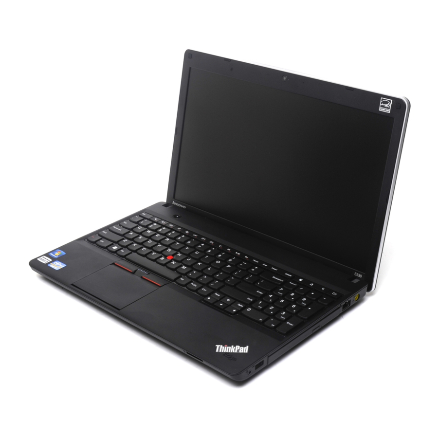
Page 54: Front View
Front view For some models: Integrated camera Media card reader slot Built-in microphones Fingerprint reader (on some models) ac power connector Touch pad RJ45 Ethernet connector TrackPoint buttons Optical drive or blank bezel TrackPoint pointing stick ® Always On USB connector UltraNav pointing device Combo audio jack... - Page 55 For other models: Integrated camera System status indicator Built-in microphones Media card reader slot Built-in stereo speakers Fingerprint reader (on some models) ac power connector Touch pad RJ45 Ethernet connector TrackPoint buttons TrackPoint pointing stick Optical drive or blank bezel Always On USB connector UltraNav pointing device Power button...
-
Page 56: Rear View
Rear view External monitor connector System status indicator USB connectors Security keyhole HDMI port : For the description of the system status indicator, see Chapter 5 “Status indicators” on page 43. Bottom view Small bottom cover Large bottom cover Battery pack latches Built-in stereo speakers (on some models) Battery pack : The wireless WAN card or mSATA solid state drive, and the backup battery are located underneath... - Page 57 CRUs, you can either install the CRU yourself or you can request that a Service Provider install the CRU according to the warranty service for your product. If you intend on installing the CRU, Lenovo will ship the CRU to you. CRU information and replacement instructions are shipped with your product and are available from Lenovo at any time upon request.
-
Page 58: Major Frus And Crus
Major FRUs and CRUs FRU description Self-service CRU Optional-service CRU LCD unit Keyboard bezel Hardware Maintenance Manual... - Page 59 FRU description Self-service CRU Optional-service CRU Battery pack DC-in connector RJ45 sub card Base cover assembly Optical drive sub card Optical drive or blank bezel I/O sub card with USB connector and audio jack Wireless LAN card Wireless WAN card or mSATA solid state drive Half-size wireless WAN card bracket Backup battery Small bottom cover...
-
Page 60: Lcd Frus And Crus
LCD FRUs and CRUs FRU description Self-service CRU Optional-service CRU LCD bezel Hinges Hardware Maintenance Manual... -
Page 61: Looking Up Fru Information
FRU description Self-service CRU Optional-service CRU Wireless antenna assembly Integrated camera assembly LCD rear cover LCD cable LCD panel Looking up FRU information For detailed FRU information, including part numbers, descriptions, and substitution part numbers, go to http://www.lenovo.com/serviceparts-lookup. Chapter 7 Locations... - Page 62 Hardware Maintenance Manual...
-
Page 63: Chapter 8. Fru Replacement Notices
Lenovo will ship the CRU to you. CRU information and replacement instructions are shipped with your product and are available from Lenovo at any time upon request. You can find a list of CRUs for your product in this Hardware Maintenance Manual. An electronic version of this manual can be found at http://www.lenovo.com/support. -
Page 64: Retaining Serial Numbers
If you replace the system board, you must restore the serial number of the system unit to its original value. Before replacing the system board, save the original serial number by doing the following: 1. Install the LENOVO ThinkPad Hardware Maintenance Diskette Version 1.76 or later, and restart the computer. -
Page 65: Retaining The Uuid
When you replace the system board, you must set the UUID on the new system board as follows: 1. Install the LENOVO ThinkPad Hardware Maintenance Diskette Version 1.76 or later, and restart the computer. - Page 66 If the system board is being replaced, try to read the ECA information from the old system board and transfer the information to the new system. If the system board is inoperable, this will not be possible. Hardware Maintenance Manual...
-
Page 67: Chapter 9. Removing Or Replacing A Fru
Lenovo will ship the CRU to you. CRU information and replacement instructions are shipped with your product and are available from Lenovo at any time upon request. You can find a list of CRUs for your product in this Hardware Maintenance Manual. An electronic version of this manual can be found at http://www.lenovo.com/support. -
Page 68: Before Servicing Thinkpad Edge E530 And E530C Models
Before servicing ThinkPad Edge E530 and E530c models Some ThinkPad Edge E530 and E530c models you are servicing might have the SIM card that the customer has installed. If the computer you are servicing has the SIM card installed, remove it before you start the servicing. -
Page 69: 1020 Large Bottom Cover
Unlock the battery latch . Hold the battery lock lever in the unlocked position, and remove the battery pack When installing: Install the battery pack in the slot. Make sure that the battery latch is in the locked position. 1020 Large bottom cover For access, remove this FRU: •... -
Page 70: 1030 Small Bottom Cover
When installing: Attach the large bottom cover as shown in the following illustration. 1030 Small bottom cover For access, remove this FRU: • “1010 Battery pack” on page 62 Removal steps of small bottom cover Note: Loosen the screw When installing: Attach the small bottom cover as shown in the following illustration. Hardware Maintenance Manual... -
Page 71: 1040 Optical Drive Or Blank Bezel
1040 Optical drive or blank bezel For access, remove these FRUs in order: • “1010 Battery pack” on page 62 Removal steps of optical drive or blank bezel Step Screw (quantity) Color Torque M2 × 3 mm, wafer-head, nylon-coated (1) Black 0.181 Nm (1.85 kgf-cm) -
Page 72: 1060 Hard Disk Drive Assembly
Removal steps of memory modules Note: Your model might look slightly different from the illustration above. When installing: Note: If only one memory module is to be installed on the computer you are servicing, the memory module must be installed in SLOT-0 ( lower slot), but not in SLOT-1 ( upper slot). - Page 73 Removal steps of hard disk drive assembly Note: Your model might look slightly different from the illustration above. Step Screw (quantity) Color Torque M2 × 3 mm, wafer-head, nylon-coated (2) Black 0.181 Nm (1.85 kgf-cm) When installing: Make sure that the hard disk drive is attached firmly. Chapter 9 Removing or replacing a FRU...
-
Page 74: 1070 Pci Express Mini Card For Wireless Lan
Removal steps of hard disk drive bracket Step Screw (quantity) Color Torque M3 × 3 mm, wafer-head, nylon-coated (4) Silver 0.392 Nm (4 kgf-cm) 1070 PCI Express Mini Card for wireless LAN For access, remove these FRUs in order: • “1010 Battery pack”... -
Page 75: 1080 Pci Express Mini Card For Wireless Wan Or Msata Solid State Drive
Removal steps of PCI Express Mini Card for wireless LAN In step , unplug the connectors by using the antenna RF connector removal tool or pick the connectors with your fingers and gently unplug them in the direction of the arrows. Note: Your model might look slightly different from the illustration above. - Page 76 Removal steps of PCI Express Mini Card for wireless WAN In step , unplug the connectors by using the antenna RF connector removal tool or pick the connectors with your fingers and gently unplug them in the direction of the arrows. When installing: Plug the red cable into the jack marked MAIN, and the blue cable into the jack marked AUX on the card.
- Page 77 Removal steps of PCI Express Half Mini Card for wireless WAN In step , unplug the connectors by using the antenna RF connector removal tool or pick the connectors with your fingers and gently unplug them in the direction of the arrows. When installing: Plug the red cable into the jack marked MAIN, and the blue cable into the jack marked AUX on the card.
-
Page 78: Step Screw (Quantity)
• Ensure that you partition the mSATA solid-state drive after installing it on the computer you are servicing. Otherwise, the mSATA solid-state drive will not function correctly. For instructions on on how to partition an mSATA solid-state drive, go to http://www.lenovo.com/support/msata-fru. Torque... -
Page 79: 1090 Backup Battery
1090 Backup battery For access, remove these FRUs in order: • “1010 Battery pack” on page 62 • “1030 Small bottom cover” on page 64 Removal steps of backup battery DANGER Use only the authorized battery specified for your computer. Any other battery could ignite or explode. -
Page 80: 1100 Thermal Fan
1100 Thermal fan For access, remove these FRUs in order: • “1010 Battery pack” on page 62 • “1020 Large bottom cover” on page 63 Removal steps of thermal fan Note: Loosen the screws Note: Your model might look slightly different from the illustration above. When installing: Make sure that the connector is attached firmly to the system board. - Page 81 • “1100 Thermal fan” on page 74 Removal steps of thermal pipes Loosen the screws in ascending alphabetic order as illustrated. When attaching the thermal pipes, secure the screws in reverse order. Note: Different models might have different numbers of screws. Note: Your model might look slightly different from the illustration above.
-
Page 82: 1120 Keyboard
For models with an integrated thermal pipes 1120 Keyboard For access, remove these FRUs in order: • “1010 Battery pack” on page 62 • “1020 Large bottom cover” on page 63 Hardware Maintenance Manual... - Page 83 Removal steps of keyboard Notes: • Your model might look slightly different from the illustration above. • The location of the screws that secure the keyboard might be different from the illustration above. Refer to the watermarks printed on the computer. When installing: Make sure that the screws are fastened and the keyboard is secured.
- Page 84 Note: Your computer keyboard might look different from the illustration above. Note: Your computer keyboard might look different from the illustration above. Hardware Maintenance Manual...
- Page 85 Installation steps of keyboard To install the keyboard, do the following: 1. Attach the connectors. 2. Attach the keyboard and ensure that the keyboard edges are under the frame. Note: Your computer keyboard might look different from the illustration above. 3.
-
Page 86: 1130 Keyboard Bezel
1130 Keyboard bezel For access, remove these FRUs in order: • “1010 Battery pack” on page 62 • “1020 Large bottom cover” on page 63 • “1040 Optical drive or blank bezel” on page 65 • “1120 Keyboard” on page 76 Removal steps of keyboard bezel Note: Your model might look slightly different from the illustration above. - Page 87 For some models: Step Screw (quantity) Color Torque M2 × 5 mm, wafer-head, nylon-coated (3) Silver 0.181 Nm (1.85 kgf-cm) For other models: Torque Step Screw (quantity) Color M2 × 5 mm, wafer-head, nylon-coated (2) Silver 0.181 Nm (1.85 kgf-cm) Chapter 9 Removing or replacing a FRU...
-
Page 88: 1140 Cpu
When installing: Make sure that the connectors are attached firmly to the system board. In step , release the keyboard bezel from the frame using a plastic pry tool as shown in the following illustration. 1140 CPU For access, remove these FRUs in order: •... -
Page 89: 1150 System Board Assembly
Removal steps of CPU Rotate the head of the screw in the direction shown by the arrow to release the lock; then remove the When installing: Place the CPU above the CPU socket, and then rotate the head of the screw in the direction shown by the arrow to secure the CPU. - Page 90 • “1020 Large bottom cover” on page 63 • “1030 Small bottom cover” on page 64 • “1040 Optical drive or blank bezel” on page 65 • “1050 Memory modules” on page 65 • “1060 Hard disk drive assembly” on page 66 •...
- Page 91 For models with an integrated thermal module When installing: Make sure that the connectors are attached firmly to the system board. Chapter 9 Removing or replacing a FRU...
-
Page 92: 1160 Speaker Assembly
Step Screw (quantity) Color Torque M2 × 5 mm, wafer-head, nylon-coated (3) Silver 0.181 Nm (1.85 kgf-cm) When installing: Make sure that the connector is attached firmly to the system board. 1160 Speaker assembly For access, remove these FRUs in order: •... - Page 93 Step Screw (quantity) Color Torque M2 × 2 mm, wafer-head, nylon-coated, big head (4) Black 0.181 Nm (1.85 kgf-cm) When installing: Attach the speaker assembly and route the cable as shown in the following figure, and make sure that the speaker connector is attached firmly. Chapter 9 Removing or replacing a FRU...
- Page 94 For other models: Step Screw (quantity) Color Torque M2 × 2 mm, wafer-head, nylon-coated, big head (4) Black 0.181 Nm (1.85 kgf-cm) When installing: Attach the speaker assembly and route the cable as shown in the following figure, and make sure that the speaker connector is attached firmly. Hardware Maintenance Manual...
-
Page 95: 1170 Power Button Sub Card
1170 Power button sub card For access, remove these FRUs in order: • “1010 Battery pack” on page 62 • “1020 Large bottom cover” on page 63 • “1040 Optical drive or blank bezel” on page 65 • “1120 Keyboard” on page 76 •... -
Page 96: 1180 I/O Sub Card With Usb Connector And Audio Jack
1180 I/O sub card with USB connector and audio jack For access, remove these FRUs in order: • “1010 Battery pack” on page 62 • “1020 Large bottom cover” on page 63 • “1040 Optical drive or blank bezel” on page 65 •... -
Page 97: 1190 Rj45 Sub Card
1190 RJ45 sub card For access, remove these FRUs in order: • “1010 Battery pack” on page 62 • “1020 Large bottom cover” on page 63 • “1040 Optical drive or blank bezel” on page 65 • “1120 Keyboard” on page 76 •... - Page 98 Removal steps of RJ45 sub card When installing: Make sure that the connector is attached firmly to the system board. Torque Step Screw (quantity) Color M2 × 5 mm, wafer-head, nylon-coated (1) Silver 0.181 Nm (1.85 kgf-cm) Hardware Maintenance Manual...
-
Page 99: 1200 Optical Drive Sub Card
1200 Optical drive sub card For access, remove these FRUs in order: • “1010 Battery pack” on page 62 • “1020 Large bottom cover” on page 63 • “1040 Optical drive or blank bezel” on page 65 • “1120 Keyboard” on page 76 •... -
Page 100: 1210 Lcd Unit
Step Screw (quantity) Color Torque 0.181 Nm M2 × 5 mm, wafer-head, nylon-coated (1) Silver (1.85 kgf-cm) 1210 LCD unit For access, remove these FRUs in order: • “1010 Battery pack” on page 62 • “1020 Large bottom cover” on page 63 •... - Page 101 In step , release the wireless antenna cables from the cable guides. Chapter 9 Removing or replacing a FRU...
- Page 102 In step , release wireless antenna cables from the cable guides. Hardware Maintenance Manual...
-
Page 103: 1220 Base Cover Assembly And Dc-In Connector
1220 Base cover assembly and DC-in connector For access, remove these FRUs in order: • “1010 Battery pack” on page 62 • “1020 Large bottom cover” on page 63 • “1030 Small bottom cover” on page 64 • “1040 Optical drive or blank bezel” on page 65 •... - Page 104 Applying labels to the base cover The new base cover FRU is shipped with a kit containing labels of several kinds. The following illustration shows the correct location of each label. Hardware Maintenance Manual...
-
Page 105: 2010 Lcd Bezel Assembly
If the Windows Certificate of Authentication (COA) label is attached to a part that is replaced, return the old part with the label attached to the customer, or provide a letter to the customer stating what the label was originally on the computer and what the label part number, serial number, and product key were. When you replace the base cover, apply the following labels: FCC label Serial number label... - Page 106 • “1120 Keyboard” on page 76 • “1130 Keyboard bezel” on page 80 • “1190 RJ45 sub card” on page 91 • “1210 LCD unit” on page 94 Removal steps of LCD bezel assembly Step Screw cap Screw (quantity) Color Torque M2 ×...
-
Page 107: 2020 Lcd Panel And Hinges
2020 LCD panel and hinges For access, remove these FRUs in order: • “1010 Battery pack” on page 62 • “1020 Large bottom cover” on page 63 • “1030 Small bottom cover” on page 64 • “1040 Optical drive or blank bezel” on page 65 •... - Page 108 When installing: Make sure that the LCD connector is attached firmly. Hardware Maintenance Manual...
-
Page 109: 2030 Integrated Camera And Lcd Cables
Removal steps of hinges Torque Step Screw (quantity) Color M2 × 3 mm, wafer-head, nylon-coated, small head (6) Black 0.181 Nm (1.85 kgf-cm) 2030 Integrated camera and LCD cables For access, remove these FRUs in order: • “1010 Battery pack” on page 62 •... - Page 110 Removal steps of integrated camera Step Screw (quantity) Color Torque M2 × 3 mm, wafer-head, nylon-coated (1) Black 0.181 Nm (1.85 kgf-cm) When installing: Make sure that the connector is attached firmly. Hardware Maintenance Manual...
-
Page 111: 2040 Wireless Antenna Assembly And Lcd Rear Cover Assembly
Removal steps of LCD cables 2040 Wireless antenna assembly and LCD rear cover assembly For access, remove these FRUs in order: • “1010 Battery pack” on page 62 • “1020 Large bottom cover” on page 63 • “1030 Small bottom cover” on page 64 •... - Page 112 Removal steps of wireless antenna assembly and LCD rear cover assembly Release the antenna cables from the cable guides on the LCD rear cover assembly. Note: Your model might not have the wireless WAN antenna assembly. Note: Your model might not have the wireless WAN antenna assembly. Cable routing: When you install the wireless antenna assembly, route the cables as shown in the following figures.
- Page 113 Note: Your model might not have the wireless WAN antenna assembly. Chapter 9 Removing or replacing a FRU...
- Page 114 Hardware Maintenance Manual...
-
Page 115: Appendix A. Notices
Lenovo representative for information on the products and services currently available in your area. Any reference to a Lenovo product, program, or service is not intended to state or imply that only that Lenovo product, program, or service may be used. Any functionally equivalent product, program, or service that does not infringe any Lenovo intellectual property right may be used instead. -
Page 116: Electronic Emission Notices
Electronic emission notices For electronic emission information on Class B digital devices, refer to the corresponding information in the User Guide. Trademarks The following terms are trademarks of Lenovo in the United States, other countries or both: Lenovo ThinkPad TrackPoint UltraNav Microsoft, Windows, and Windows Server are trademarks of the Microsoft group of companies. - Page 118 Part Number: 0B48439_01 Printed in China (1P) P/N: 0B48439_01 *1P0B48439_01*...
Need help?
Do you have a question about the ThinkPad Edge E530 and is the answer not in the manual?
Questions and answers