Table of Contents

Related Manuals for Redvision RV X-SERIES


Summary of Contents for Redvision RV X-SERIES
-
Page 1: User Manual
X-SERIES USER MANUAL Products Covered: RV X-SERIES™ PTZ Positioning Camera RVX-PSU Power Supply RVX-PSU-ALM16 Power Supply with Alarm Module RVX-PSU-ALM16-W PSU with Wireless PIR module [RVX V9.2.7] © 2012 Redvision CCTV Limited. All rights reserved. -
Page 2: Table Of Contents
SETTING THE CAMERA PROTOCOL SETTING THE CAMERA BAUD RATE SETTING THE CAMERA RS485 TERMINATION REAL TIME CLOCK (RTC) REPLACING THE DIP SWITCH COVER POWER SUPPLY INSTALLATION REDVISION POWER SUPPLY(RVX-PSU) VOLTAGE RVX-PSU INTERNAL CONNECTIONS 3.3.1 MAINS INPUT 3.3.2 CONNECTIONS TO CAMERA – 8 WAY BLOCK 3.3.3... - Page 3 X-SERIES USER MANUAL NAVIGATING THE MENUS MENU NAVIGATION - FLOW CHART 6.1.1 ACCESS MAIN MENU FROM 3RD PARTY CONTROLLERS 6.1.2 EXIT MENU LOGIN LOGIN EXPIRY SET UP 6.4.1 ENTER DATE & TIME CLOCK 6.4.2 DAYLIGHT SAVING 6.4.3 LANGUAGE OPTIONS 6.4.4 DISPLAY 6.4.5 PASSWORDS...
- Page 4 X-SERIES USER MANUAL PRESETS & TOURS 10.1 FOCUS SHIFT 10.2 PRESET 10.2.1 SET A PRESET (USING CAMERA INTERNAL MENU) 10.2.2 EDIT PRESET 10.2.3 PRESET SPEED 10.3 TOURS 10.3.1 TOUR 1 TO 8 10.4 RESTORE (PRESETS AND TOURS) 10.4.1 RESTORE TO NUMBER – EITHER TOUR OR PRESET NUMBER 10.4.2 TIMED RESTORE WEEKDAY 10.4.3...
- Page 5 X-SERIES USER MANUAL NOTES...
-
Page 6: Installing The Camera Head
X-SERIES USER MANUAL INSTALLING THE CAMERA HEAD CONVERT DOME TO BALL PTZ CONFIGURATION The RVX Series can be mounted as a dome or ball PTZ configuration. To convert the dome to ball PTZ remove the M4 button head screws with 2.5mm allen key provided. See FIG A below. FIG B MOUNTING ORIENTATION OBSERVE THE FOLLOWING PRECAUTIONS WHEN INSTALLING: 1. -
Page 7: Bracket Types
X-SERIES USER MANUAL A A T T T T A A C C H H I I N N G G C C A A M M E E R R A A T T O O T T H H E E B B R R A A C C K K E E T T : : See Fig C & D below 1. -
Page 8: How To Configure The Camera
X-SERIES USER MANUAL HOW TO CONFIGURE THE CAMERA REMOVING THE DIP SWITCH SCREW COVER There are two rows of DIP switches located behind the large screw cap (see FIG 1 below). Use flat bladed screw driver to remove by turning anti-clockwise to unscrew. 2.1.1 CAMERA ORIENTATION FOR SETTING DIP SWITCHES CAUTION:... -
Page 9: Setting The Camera Address
X-SERIES USER MANUAL SETTING THE CAMERA ADDRESS See table TABLE 1 below for guidance on DIP switch setting for each Camera address. ‘0’ represents OFF (up) and ‘1’ represents ON (down). TABLE 1 ROW ‘B’ DIP SWITCH ROW ‘B’ DIP SWITCH CAMERA CAMERA ADDRESS... -
Page 10: Setting The Camera Rs485 Termination
X-SERIES USER MANUAL SETTING THE CAMERA RS485 TERMINATION The default position is ON (down). TABLE 4 ROW ‘A’ DIP SWITCH TERMINATION CAUTION: Termination switch should be set to ON (down) if: The Camera is being run on coax protocol ... -
Page 11: Power Supply Installation
MUST BE CARRIED OUT BY A SUITABLY QUALIFIED PERSON. Camera Warranty is void unless it is installed using one of the following Redvision power supplies and a Redvision supplied fly lead (Composite cable): Using the wrong type of 3rd party PSU could compromise safety and damage the camera unit. -
Page 12: Connections To Camera - 8 Way Block
X-SERIES USER MANUAL 3.3.2 CONNECTIONS TO CAMERA - 8 WAY TERMINAL BLOCK TABLE 7 UMBILICAL LEAD TO CAMERA PCB IDENT Normally Closed Normally Closed VIDEO Coax signal (BNC 7) V-GND Coax screen RS485(A) White RS485(B) Orange +24V Black and cable screen 3.3.3 CONNECTIONS TO CONTROL - 8 WAY TERMINAL BLOCK TABLE 8... -
Page 13: Rvx-Psu-Alm16 (Psu With Alarm Module)
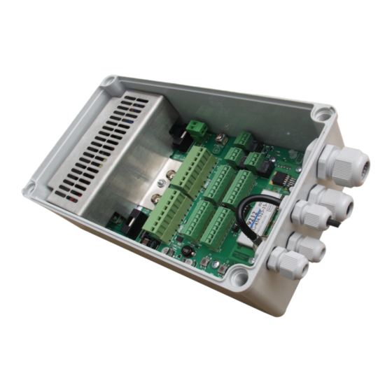
X-SERIES USER MANUAL FIG 8 METAL COVER CONTROL CONNECTIONS MAINS INPUT ALARM INPUTS DOME CONNECTIONS EARTH TERMINAL ALARM OUTPUTS CONFIG DIP SWITCH (S5) RVX-PSU-ALM16 (PSU WITH ALARM MODULE) WARRANTY & SAFETY NOTICE: DISCONNECT ALL POWER BEFORE OPENING OR WORKING ON THE RVX-PSU-ALM16 POWER SUPPLY UNIT WITH EMBEDDED ALARM CARD. THIS PROTECTS HIGH VOLTAGE COMPONENTS. -
Page 14: Connections To Camera (8 Way Block)
X-SERIES USER MANUAL 4.2.2 CONNECTIONS TO CAMERA - 8 WAY TERMINAL BLOCK TABLE 12 UMBILICAL LEAD TO CAMERA PCB IDENT Normally Closed Normally Closed VIDEO Coax signal (BNC 7) V-GND Coax screen RS485(A) White (+IVE) RS485(B) Orange +24V Black and cable screen 4.2.3 CONNECTIONS TO CONTROL - 8 WAY TERMINAL BLOCK TABLE 13... -
Page 15: Baud Rate - Alarm Module
X-SERIES USER MANUAL 4.3.1 PROTOCOL - ALARM MODULE TABLE 16 P P r r o o t t o o c c o o l l B B a a u u d d R R a a t t e e R R S S 4 4 8 8 5 5 T T e e r r m m i i n n a a t t i i o o n n D D I I P P S S W W I I T T C C H H N N o o . -
Page 16: Normally Open/Closed Alarm Inputs
X-SERIES USER MANUAL 4.4.2 RELAY OUTPUTS (VOLT FREE) There are 3 relay outputs NO/NC 0V output: Alarms, Wash and Aux. ALARMS are tied into ALARM INPUTS. WASH is activated by a wash command or by user defined preset. AUX can be triggered by ACTIVE ALARMS or IR NIGHT MODE SWITCHING. NORMALLY OPEN/NORMALLY CLOSED ALARM INPUTS See S3 &... -
Page 17: Wireless Alarm Card (Wireless Pir Detector)
BY A SUITABLY QUALIFIED PERSON. FACTORY FITTED WIRELESS CARD (RV-PSU-ALM16-W) The Redvision Wireless Card is compatible with the Redvision Wireless PIR, Luminite Genesis Range and the Redwall Wireless Transmitter Module Part Code WF434T, (wireless enables Redwall PIRs). This PSU is compatible with the following RVX SERIES PTZs: R R V V X X 1 1 8 8 , , R R V V X X 1 1 8 8 - - I I R R , , R R V V X X 1 1 8 8 - - W W , , R R V V X X 1 1 8 8 - - I I R R - - W W , , R R V V X X 2 2 8 8 , , R R V V X X 2 2 8 8 - - I I R R , , R R V V X X 2 2 8 8 - - W W , , R R V V X X 2 2 8 8 - - I I R R - - W W . -
Page 18: Positioning Of Rvx-Psu-Alm16-W
X-SERIES USER MANUAL DIP SWITCH SETTINGS The WIRELESS Alarm Module has a single 8 Way DIP SWITCH. (See FIG 8 below). • 1 to 3 dip switches are not used & should be left ‘ON’ (UP) TABLE 19 • Switches 4 to 8 (Dome Head Site Code) provide up to 32 (1 to 16 shown in TABLE 19) channels of wireless transmission to DOWN = M enable alarm activation. -
Page 19: Navigating The Menus
X-SERIES USER MANUAL NAVIGATING THE MENUS MENU NAVIGATION - FLOW CHART Use joystick/Arrow keys to navigate the menu options. See FIG 9, page 15. 6.1.1 ACCESS MAIN MENU FROM 3rd PARTY CONTROLLERS As most keyboards differ in the way they access the Camera’s MAIN MENU it is recommended the user refers to the specific keyboard manual for the control system they are using. - Page 20 FIG 9 ENTER DATE/TIME DATE/TIME POSITION 6.1 MENU NAVIGATION - FLOW CHART CAMERA TITLE DAYLIGHT SAVING CAMERA TITLE SCREEN POSITION MAIN MENU LANGUAGE SHOW PRESETS DURING TOURS DISPLAY PRESET TEXT POSITION LOG IN PASSWORDS TEXT BACKGROUND HANGING DATUM CHECK HANGING ARMS OUT CAMERA ORIENTATION SET UP UPRIGHT...
- Page 21 X-SERIES USER MANUAL JOYSTICK JOYSTICK CURVE ZOOM RATIO WIPER JOYSTICK SPEED PAN LIMITS INTERMITTENT TILT LIMITS WIPER TIME OUT SHORTCUTS WIPER/WASH SHORTCUT PRESET WIPER SHORTCUT PRESET NIGHT MODE SHORTCUT PRESETS WASH SHORTCUT PRESET AUX RELAY FUNCTION COMPATIBILITY MODE STANDARD BBV TX1000/1500 SET PRESET EDIT PRESETS PRESETS &...
- Page 22 X-SERIES USER MANUAL 6.4.2 DAYLIGHT SAVING Default setting is AUTO. LOGIN > MAIN MENU > S S E E T T U U P P > > DAYLIGHT SAVING MOVE TO SET AUTO, OFF (+0), ON (+1) MOVE TO SAVE &...
- Page 23 DATUM CHECK The Redvision X-Series Camera is programmed to perform a datum check every 24 hours. The Camera will pan and tilt for a few seconds while it undergoes a self diagnostic test and re-checks its alignment. When the process is complete the Camera will revert to its previous activity including any tours with presets.
- Page 24 X-SERIES USER MANUAL 6.4.7 CAMERA ORIENTATION The Camera orientation automatically sets the maximum tilt up/down positions depending on whether the Camera is in upright or hanging down mode. The maximum tilt restrictions can be deactivated to allow full tilt movement. See 9.6. ...
-
Page 25: Night Mode
6.4.10 DIAGNOSTICS There are five diagnostic screens which display useful information for the technician and remote help diagnostics for Redvision’s technical support helpdesk. They are not configurable. To access the diagnostic screens. LOGIN > MAIN MENU > S S E E T T U U P P > > DIAGNOSTICS ... -
Page 26: Camera Settings
X-SERIES USER MANUAL ON TIMES The IR PODS (RVX-IR version) & Camera can be programmed to switch on/off colour/mono at pre-determined times. There are 24 block positions representing each hour of the day. LOGIN > MAIN MENU > NIGHT MODE > IR ON TIMES ... - Page 27 X-SERIES USER MANUAL 8.1.5.2 BACKLIGHT COMPENSATION The ability of a Camera to compensate in cases where a subject with a large amount of background light would otherwise be obscured by blooming or silhouetting. Can be turned ON or OFF. Default is off. ...
- Page 28 X-SERIES USER MANUAL LOW LIGHT MODE SETTINGS The following settings apply when the camera switches from D D A A Y Y M M O O D D E E S S E E T T T T I I N N G G S S (colour) to N N I I G G H H T T M M O O D D E E > > L L O O W W L L I I G G H H T T M M O O D D E E S S E E T T T T I I N N G G S S 8.2.1 COLOUR/MONO...
- Page 29 X-SERIES USER MANUAL 8.2.6.2 BACKLIGHT COMPENSATION The ability of a Camera to compensate in cases where a subject with a large amount of background light would otherwise be obscured by blooming or silhouetting. LOGIN > MAIN MENU > CAMERA SETTINGS > LOW LIGHT MODE SETTINGS > ADV CONFIG > BACKLIGHT COMPENSATION ...
- Page 30 X-SERIES USER MANUAL IR MODE SETTINGS 8.3.1 FOCUS CORRECTION LOGIN > MAIN MENU > CAMERA SETTINGS > IR MODE SETTINGS > FOCUS CORRECTION MOVE TO SELECT ON OR OFF(DEFAULT) MOVE TO SAVE & EXIT TECH SUPPORT COMMENT: For typical CCTV applications it is recommended to leave the setting to default ‘OFF’.
- Page 31 X-SERIES USER MANUAL 8.3.6.3 IMAGE STABILISER ( ( S S O O N N Y Y M M O O D D U U L L E E ) ) LOGIN > MAIN MENU > CAMERA SETTINGS > IR MODE SETTINGS > ADV CONFIG > IMAGE STABILISER ...
- Page 32 X-SERIES USER MANUAL VIDEO LIFT High frequency video lift can be set between 0 & 8. Default is zero. TECH SUPPORT COMMENT: Technician should attempt to compensate for poor cable runs using video lift, before using video gain LOGIN > MAIN MENU > CAMERA SETTINGS > VIDEO LIFT ...
- Page 33 X-SERIES USER MANUAL JOYSTICK & WIPER JOYSTICK CURVE There are three settings. The following options describe how sensitive the joystick is to small movements. Linear is most sensitive, quasi linear and non-linear allow for finer control at low speeds, ramping up with larger movements. Quasi linear is the default.
- Page 34 X-SERIES USER MANUAL PAN LIMITS Program Camera to pan only within pre-defined left and right limits. This can be useful if the Camera is mounted on the corner of a building or a wall. If presets are programmed the Camera will stay within the permitted limits, and not take the shortest route . ...
- Page 35 Neutral Density (ND) filter to compensate for focus shift when the camera switches to mono. The best way to ensure optimum focus on THE REDVISION X-SERIES PTZ/Dome camera is to set ‘night-time’ presets when the light levels are low and the camera is in mono. If using a PTZ fitted with IR, the IR pods should be switched ON (RVX-IR versions only).
- Page 36 X-SERIES USER MANUAL 10.2.2.3 CLEAR PRESET – (DELETES INDIVIDUAL PRESET & CONTENT) LOGIN > MAIN MENU > PRESETS & TOURS > PRESETS > EDIT PRESETS MOVE TO SELECT PRESET NUMBER TO BE EDITED TO SELECT PRESET TO SELECT YES/NO ...
- Page 37 X-SERIES USER MANUAL 10.3.1.4 TOUR DWELL TIME The time the Camera dwells between each preset can be programmed between 1 & 120 seconds. Default is 8 seconds. LOGIN > MAIN MENU > PRESETS & TOURS > TOURS > DWELL ...
- Page 38 X-SERIES USER MANUAL 10.4.4 RESTORE MODE (PRESETS & TOURS) Use this option to make the Camera revert to a tour or preset after a specified delay period (in seconds) of inactivity (see RESTORE DELAY 10.4.5). Restore modes: LOGIN > MAIN MENU > PRESETS & TOURS > RESTORE > RESTORE MODE ...
- Page 39 The alarm cycle time programmed in seconds is the time it takes to tour the presets of still active alarms. Default is 3 seconds. This function will be ignored if alarms are connected directly to third party control equipment rather than the Redvision Alarm Module (RV-PSU-ALM16) & (RV-PSU-ALM16-W) ...
- Page 40 X-SERIES USER MANUAL 12.4 EDIT ALARMS Use this menu to program how alarms are configured e.g. Create a weekday time schedule when alarms are automatically enabled or disabled and the type of action required when an alarm is enabled & subsequently activated etc. Alarm dwell (12.4.7) time can also be programmed in the menu.
- Page 41 On multiple alarms, presets will be called up in sequence. the dwell time (in seconds) between each alarm can be programmed. Default is 5 seconds. This function will be ignored if alarms are connected directly to third party control equipment rather than the Redvision alarm module. TECH SUPPORT COMMENT: See ALARM OVER-RIDE 12.2 and ALARM CYCLE TIME 12.3 - the new alarm...
-
Page 42: Contact Technical Support
X-SERIES USER MANUAL CONTACT TECHNICAL SUPPORT Redvision Technical Support Helpline tel: +44 (0) 1420 448 448 email: support@redvisioncctv.com web: www.redvisioncctv.com/support TECHNICAL SPECIFICATION CAMERA TELEMETRY I I m m a a g g e e s s e e n n s s o o r r Sony EXview 1/4”... - Page 43 Redvision or in accordance with Redvision’s written instructions. In the case of any such return the buyer shall bear the risk of loss or damage and shall prepay all transportation charges to Redvision.
- Page 44 X-SERIES USER MANUAL X-SERIES...
Need help?
Do you have a question about the RV X-SERIES and is the answer not in the manual?
Questions and answers