Table of Contents
Advertisement
Advertisement
Table of Contents

Related Manuals for Redvision X2 COMBAT Series


Summary of Contents for Redvision X2 COMBAT Series
- Page 1 X2 COMBAT IP PTZ cameras Quick guide on page 4! V2.0 January 2020...
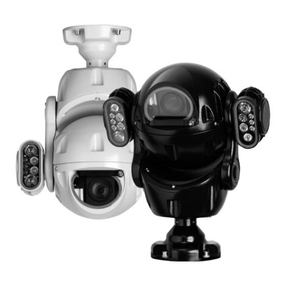
- Page 2 Welcome to Redvision Thank you for choosing the Redvision X2 COMBAT camera. X2 COMBAT has been carefully developed as a leading-edge, precision-technology surveillance camera, offering superb image quality through 3MP resolution, excellent low-light performance, combined with powerful lighting options. X2 COMBAT has been designed to be maintenance-free and able to operate in a wide variety of environments and applications.
-
Page 3: Table Of Contents
Contents i Quick Guide to accessing the camera via the web browser function ii Safety Guide 1.0 Installing the camera head 1.1 Converting hanging orientation to upright 1.2 Bracket installation 1.3 Cantilever mode – moving the camera head forwards 2.0 Power supply installation and setup 2.1 Power supply specifications 2.2 Power supply layout 2.3 PSU connections... -
Page 4: Quick Guide To Accessing The Camera Via The Web Browser Function
Quick-Guide for X2 COMBAT: Your X2 COMBAT camera uses a built-in web server, to allow configuration from any web-browser application. For full control and setup; Internet Explorer® v7 to 11 must be used. An ActiveX control will be required to install on the computer, to allow full access to all setup and control features via the browser. - Page 5 Running Internet Explorer permanently in Administrator mode It is possible to run Internet Explorer browser from a desktop shortcut, permanently in Administrator mode. To do this, right-click over the Internet Explorer icon and left-click the “Properties” option: Next, click the “Advanced” button: X2 COMBAT Install Guide 2.0...
- Page 6 Then, check the “Run as administrator” box and click OK to save the setting: Click OK to close the properties box. Each time you use this icon, Internet Explorer browser will launch in administrator mode. Note that only the shortcut you have modified will run as administrator; launching from other, unmodified sources will not apply Administrator mode.
- Page 7 • Click to proceed. The main page is displayed. Main Page Layout From the main page, you can view real-time images, receive alarm and fault notifications, set parameters, change the password, and log out of the system. Fig 1 below shows the main page layout. Fig 1.
- Page 8 Viewing Live Video To browse real-time videos, click Live Video. The Live Video page is displayed, as shown in Fig 4. Fig. 4 Live Video page Setting a new fixed IP address The X2 COMBAT camera has been shipped with a static IP address of 192.168.0.120. This will need to be changed to match the IP address range of your network.
- Page 9 Choose TCP/IP v4 or v6 as required; type the new fixed IP address of the camera into the IP Address field; with ⚫ Subnet Mask and Default Gateway address (if connecting exclusively to an NVR; use the NVR’s fixed IP address for the Gateway).
-
Page 10: Safety Guide
ii. Safety guide THIS CAMERA SYSTEM MUST BE INSTALLED, OPERATED AND MAINTAINED IN ACCORDANCE WITH THE MANUFACTURER’S SPECIFICATIONS. 1. Installation of this system should be carried out by suitably trained and qualified technicians in accordance with local electrical codes. 2. To prevent the risk of electric shock do not expose the electrical connectors on the camera or the inside of the control box to water before or during installation. -
Page 11: Installing The Camera Head
1.0 Installing the camera head X2 COMBAT is supplied with an industry-standard 4” PCD base, for mounting directly onto poles, towers and brackets using a compatible 4” PCD mount (shown below in Fig. A). The base provides a secure eyelet for attaching the supplied Safety-Bond. Ensure the Safety-Bond is securely fitted at all times. -
Page 12: Bracket Installation
OBSERVE THE FOLLOWING PRECAUTIONS WHEN INSTALLING: 1. Mount the Camera in a position where it cannot be interfered with either intentionally or accidentally. 2. The mounting surface should be capable of supporting the weight of both the Camera and mounting brackets under all expected conditions of load, vibration and temperature. -
Page 13: Cantilever Mode - Moving The Camera Head Forwards
1.3 Cantilever Mode - Moving the tilt-arms forwards X2 COMBAT is able to cantilever the camera head forwards by approx. 15°, in order to see the base area of a tower or pole clearly. In effect, this gives X2 COMBAT the ability to view a full 180° in the tilt axis, ensuring nothing is missed. -
Page 14: Power Supply Installation And Setup
MUST BE CARRIED OUT BY A SUITABLY QUALIFIED PERSON The camera warranty is void unless it is installed using a Redvision power supply unit (PSU) and a Redvision supplied umbilical/multicore lead (Composite cable). Using the wrong type of 3rd party PSU could compromise safety and damage the camera unit. -
Page 15: Power Supply Layout
2.2 Power supply layout The Redvision power supply outputs 24V DC and is supplied with an IP67 rated ABS junction box. Green Power ON Camera DC supply fuse 3.5A Camera umbilical connections 240VAC Mains supply fuse 3.5A External connections 2.3 PSU connections... -
Page 16: Mains Power Connections
2.4 Mains power connections (P1) MAINS POWER IDENT LIVE (BROWN) 110/230 VAC Connection via 2- way terminal block NEUTRAL (BLUE) Connection via 2-way terminal block EARTH GREEN/YELLOW Connection via terminal screw NOTE: Earth connection requires a 4mm red spade loop (supplied with PSU) to be fitted at the time of installation. -
Page 17: Primary Network Connection
2.6 Primary network connection RJ45 SOCKET The socket is a typical Ethernet 10/100BASE-T type, for connection of a Cat 5e cable, wired to the T568A or T568B scheme. The typical wire colours noted below are of the T568B scheme. The camera supports automatic polarity and automatic crossover (Auto MDI/MDIX) to simplify installation cabling. -
Page 18: Umbilical Cable Connections
2.7 Umbilical cable connections Standard and Alarm models: Two types of umbilical cable are supplied, dependent upon the camera model used. The Standard camera uses a 7-pin Amphenol connector, the Alarm model uses a 14-pin Amphenol connector, with additional wires for the alarm signals. The wiring table below covers both types of connectors. -
Page 19: External Alarm Connections (Alarm-Capable Models Only)
2.8 External Alarm connections (for alarm-capable models only) Connections are provided for external alarm signals from PIRs, door contacts, or other, voltage- free opening or closing contacts. Note: All alarm inputs are voltage free and MUST NOT be connected to any powered contacts. Permanent damage may result from failure to correctly connect the alarm inputs. -
Page 20: Camera Setup
4.0 Camera setup Please refer to page 3 of this manual for a quick-guide to connecting to the camera. Please refer to the online “X2 COMBAT- Web Setup Guide” for a detailed description of settings. This guide can be downloaded from www.redvisioncctv.com X2 COMBAT Install Guide 2.0... -
Page 21: Technical Specifications
5.0 X2 COMBAT Technical specifications Camera Specification Events 30x optical zoom, 3MP, 1/2.8 CMOS Camera module Alarms 4 in, 2 out Low-Light sensor, True-ICR 4.5mm ~ 135mm FOV: 59.8° (Wide) ~ Lens Intelligent Tracking 2.3° (Tele) Colour: 0.01Lux @ F1.2 Email notifications Sensitivity Monochrome: 0.0001Lux @ F1.2... -
Page 22: Warranty Information
+44 (0)1420 448 448 for an RMA number or visit www.redvisioncctv.com for more information. Copyright © 2008 - 2020 Redvision CCTV Ltd. Content subject to change without prior notice. E&OE. All rights reserved. Redvision CCTV Limited, Alpha House, Blacknest Road, Blacknest, Alton, GU34 4PX, United Kingdom Company registration: UK3952814...
Need help?
Do you have a question about the X2 COMBAT Series and is the answer not in the manual?
Questions and answers