Page 1
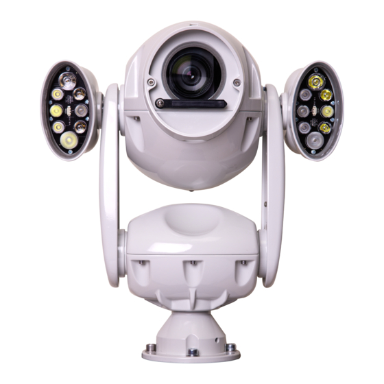
2021 Generation 3 IP PTZ cameras This Guide covers these products: X2 COMBAT X3 STORM (Stainless Steel) Quick guide on page 4! X4 COMMANDER RVX2 PSU PoE 802.3bt variants Proud UK Design and Manufacture-----UK Service and Support v0.7 June 2021...
Page 2
Welcome to Redvision Thank you for choosing a Redvision rugged IP PTZ camera. Your camera has been carefully developed and manufactured in the United Kingdom as a leading-edge, precision-technology surveillance camera, offering superb image quality, excellent low-light performance, combined with powerful lighting options. Your camera has been designed to be maintenance-free and able to operate in a wide variety of environments and applications.
Contents i Quick Guide to accessing the camera via the web browser function ii Safety Guide iii Identifying your camera 1.0 Installing the camera head 1.1 Converting hanging orientation to upright 1.2 Bracket installation 1.3 Cantilever mode – moving the camera head forwards 2.0 Power supply installation and setup 2.1 Power supply specifications 2.2 Power supply layout...
Quick-Guide for to essential configuration: Your camera uses a built-in web server, to allow configuration from any web-browser application. For full control and setup; Internet Explorer® v7 to 11 must be used. An ActiveX control will be required to install on the computer, to allow full access to all setup and control features via the browser.
Page 5
Running Internet Explorer permanently in Administrator mode It is possible to run Internet Explorer browser from a desktop shortcut, permanently in Administrator mode. To do this, right-click over the Internet Explorer icon and left-click the “Properties” option: Next, click the “Advanced” button: 2021 X-Series Install Guide 0.7 June 2021...
Page 6
Then, check the “Run as administrator” box and click OK to save the setting: Click OK to close the properties box. Each time you use this icon, Internet Explorer browser will launch in administrator mode. Note that only the shortcut you have modified will run as administrator;...
Page 7
Main Page Layout From the main page, you can view real-time images, receive alarm and fault notifications, set parameters, change the password, and log out of the system. Fig 1 below shows the main page layout. Fig 1. Main page layout Active X installation You will be prompted with a message “Download the latest plugins”...
Page 8
Viewing Live Video To browse real-time videos, click Live Video. The Live Video page is displayed, as shown in Fig 4. Fig. 4 Live Video page Setting a new fixed IP address The camera has been shipped with a static IP address of 192.168.0.120. This will need to be changed to match the IP address range of your network.
Page 9
Choose TCP/IP v4 or v6 as required; type the new fixed IP address of the camera into the IP Address field; with ⚫ Subnet Mask and Default Gateway address (if connecting exclusively to an NVR; use the NVR’s fixed IP address for the Gateway).
ii. Safety guide THIS CAMERA SYSTEM MUST BE INSTALLED, OPERATED AND MAINTAINED IN ACCORDANCE WITH THE MANUFACTURER’S SPECIFICATIONS. 1. Installation of this system should be carried out by suitably trained and qualified technicians in accordance with local electrical codes. 2. To prevent the risk of electric shock do not expose the electrical connectors on the camera or the inside of the control box to water before or during installation.
iii. Identifying your camera The 2020 X-Series range consists of three primary models: X2 COMBAT: • 30x optical zoom, 3MP low-light camera module. • ONVIF Profile S, G, Q Compliant • Alloy housing with marine grade finish and parts. • Integrated long-life Silicone Wiper.
1.0 Installing the camera head Your camera is supplied with an industry-standard 4” PCD base, for mounting directly onto poles, towers and brackets using a compatible 4” PCD mount (shown below in Fig. A). The base provides a secure eyelet for attaching the supplied Safety-Bond. Ensure the Safety-Bond is securely fitted at all times.
OBSERVE THE FOLLOWING PRECAUTIONS WHEN INSTALLING: 1. Mount the Camera in a position where it cannot be interfered with either intentionally or accidentally. 2. The mounting surface should be capable of supporting the weight of both the Camera and mounting brackets under all expected conditions of load, vibration and temperature.
1.3 Cantilever Mode - Moving the tilt-arms forwards Your camera is able to cantilever the camera head forwards by approx. 15°, in order to see the base area of a tower or pole clearly. In effect, this gives the camera the ability to view a full 180° in the tilt axis, ensuring nothing is missed.
MUST BE CARRIED OUT BY A SUITABLY QUALIFIED PERSON The camera warranty is void unless it is installed using a Redvision power supply unit (PSU) and a Redvision supplied umbilical/multicore lead (Composite cable). Using the wrong type of 3rd party PSU could compromise safety and damage the camera unit.
2.2 Power supply layout The Redvision power supply outputs 24V DC and is supplied with an IP67 rated ABS junction box. Green Power ON Camera DC supply fuse 3.5A Camera umbilical connections 240VAC Mains supply fuse 3.5A External connections 2.3 PSU connections...
2.4 Mains power connections (P1) MAINS POWER IDENT LIVE (BROWN) 110/230 VAC Connection via 2- way terminal block NEUTRAL (BLUE) Connection via 2-way terminal block EARTH GREEN/YELLOW Connection via terminal screw NOTE: Earth connection requires a 4mm red spade loop (supplied with PSU) to be fitted at the time of installation.
2.6 Primary network connection RJ45 SOCKET The socket is a typical Ethernet 10/100BASE-T type, for connection of a Cat 5e cable, wired to the T568A or T568B scheme. The camera supports automatic polarity and automatic crossover (Auto MDI/MDIX) to simplify installation cabling. The use of high quality, solid-copper Ethernet cable is highly recommended for reliable operation.
2.6.5 Power over Ethernet (PoE) Versions RJ45 SOCKET connections The PoE version of the camera is a fully 802.3bt 90W-compliant device. It is factory-fitted with a single RJ45 socket, which will accept both Ethernet data and power. Please ensure you follow standard Ethernet wiring conventions when connecting to the camera, or damage could occur.
2.7 Umbilical cable connections Standard and Alarm models: Two types of umbilical cable are supplied, dependent upon the camera model used. The Standard camera uses a 7-pin Amphenol connector, the Alarm model uses a 14-pin Amphenol connector, with additional wires for the alarm signals. The wiring table below covers both types of connectors.
2.8 External Alarm connections (for alarm-capable models only) Connections are provided for external alarm signals from PIRs, door contacts, or other, voltage- free opening or closing contacts. Note: Alarm inputs are “Dry”, designed to be voltage-free. Damage may occur and the warranty void if voltage is applied to the alarm input contacts! NOTE: The 'Alarm input xx Ground' connections are all common on the PCB and connected to the PSU 0V line.
4.0 Camera setup Please refer to page 3 of this manual for a quick-guide to connecting to the camera. For more detailed instructions, the “Web User Guide” can be downloaded from: https://www.redvisioncctv.com/installation-sheets/?category=x2-combat 2021 X-Series Install Guide 0.7 June 2021...
Need help?
Do you have a question about the X Series and is the answer not in the manual?
Questions and answers