Table of Contents
Advertisement
TRADESMAN
®
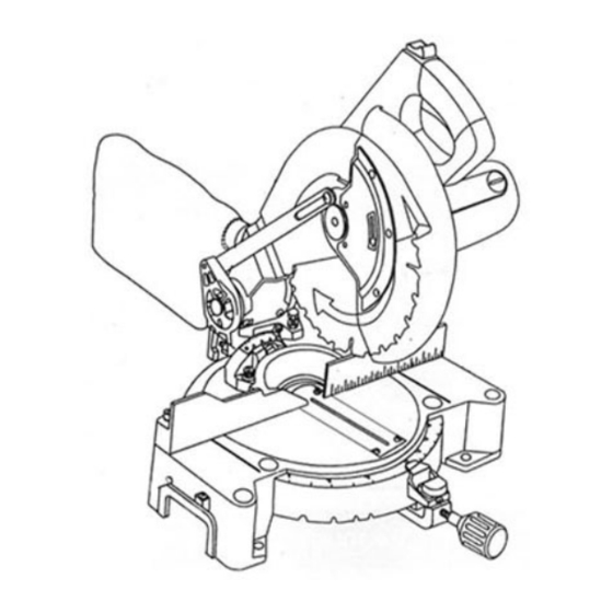
10" COMPOUND MITER SAW
Model # M2501W
Item #51470
CAUTION – FOR YOUR OWN SAFETY
READ YOUR OWNER'S MANUAL THROUGH COMPLETELY AND CAREFULLY BEFORE
ATTEMPTING TO SET-UP OR OPERATE YOUR NEW POWER TOOL.
ALL OPERATORS OF THIS EQUIPMENT SHOULD READ AND UNDERSTAND ALL SAFETY
RULES PRINTED ON THE MACHINE AND THIS OWNERS MANUAL BEFORE USE.
Your new Power Tool is a well built, carefully inspected versatile machine, capable of giving you many
years of dependable service. Your power tool comes complete in one carton with a minimum of first
assembly and setup required by you. When unpacking, be sure to check all packages and packing
material for loose parts before discarding.
NOTICE: On the nameplate of your machine you will find the serial number and MFG date code of
your unit. Please record these numbers on this manual cover for future service reference.
SERIAL #
MFG. DATE #
PURCHASE DATE:
POWER TOOL SPECIALISTS, INC. E.WINDSOR, CT 06088 PRINTED IN CHINA
www.tradesman-rexon.com
1-800-243-5114
Advertisement
Table of Contents

Related Manuals for Tradesman M2501W


Summary of Contents for Tradesman M2501W
- Page 1 TRADESMAN ® 10” COMPOUND MITER SAW Model # M2501W Item #51470 CAUTION – FOR YOUR OWN SAFETY READ YOUR OWNER’S MANUAL THROUGH COMPLETELY AND CAREFULLY BEFORE ATTEMPTING TO SET-UP OR OPERATE YOUR NEW POWER TOOL. ALL OPERATORS OF THIS EQUIPMENT SHOULD READ AND UNDERSTAND ALL SAFETY RULES PRINTED ON THE MACHINE AND THIS OWNERS MANUAL BEFORE USE.
-
Page 2: Table Of Contents
TABLE OF CONTENTS SECTION PAGE SECTION PAGE Product Specifications …………………….. Know Your Miter Saw..…………………… Power Tool Safety ..……………………….. Miter Saw Glossary ………………………. Compound Miter Saw Safety…………..Assembly……………….. Electrical Requirements and Safety……….. Adjustments………………………….. Pre Assembly……………… Operation ……………………………… Tools Required For Assembly..……………. Maintenance.……………….. -
Page 3: Power Tool Safety
POWER TOOL SAFETY CAUTION Before using your miter saw, it is critical that you read and understand these safety rules. Failure to follow these rules could result in serious injury or damage to the miter saw. 1. READ and become familiar with the entire Operators Manual. -
Page 4: Compound Miter Saw Safety
COMPOUND MITER SAW SAFETY 1. USE ONLY CROSS-CUTTING SAW BLADES. When 18. MAKE SURE the blade is not contacting the using carbide tipped blades, make sure they have a workpiece before the switch is turned ON. negative hook angle. 19. IMPORTANT: After completing the cut, release the IMPORTANT: DO NOT USE THIN KERF BLADES- power switch and wait for the blade to stop before they can deflect and contact guard and can cause... -
Page 5: Electrical Requirements And Safety
ELECTRICAL REQUIREMENTS AND SAFETY DOUBLE INSULATED 4. FUSES may “blow” or circuit breakers may trip The power tool is double insulated to provide a double frequently if: thickness of insulation between you and tool’s electrical a. MOTOR is overloaded – overloading can occur if system. - Page 6 PRE ASSEMBLY ACCESSORIES AND ATTACHMENTS RECOMMENDED ACCESSORIES Use only the recommended accessories with this saw. CAUTION Use only accessories recommended for this miter saw. Follow instructions that accompany accessories. TOOLS REQUIRED FOR ASSEMBLY Use of improper accessories may cause hazards. The use of any cutting tool except 10 inch saw blades that meet the requirements under recommended accessories is prohibited.
-
Page 7: Carton Contents
CARTON CONTENTS 2. Place the saw on a secure stationary work surface. UNPACKING YOUR MITER SAW 3. Separate all parts from the packing material. Check CAUTION each one with the illustration below to make certain all items are accounted for, before discarding any packing material. -
Page 8: Know Your Miter Saw
KNOW YOUR MITER SAW Safety lock off button Upper Blade Guard Cutting Head Handle Cover Plate Dust chute Dust Bag Lower Blade Guard Blade Miter Scale Mounting hole Base Positive Stop Locking Lever Miter handle Mounting hole Stop latch Arbor Lock Pivot bolt lock-nut Bevel Scale... -
Page 9: Miter Saw Glossary
MITER SAW GLOSSARY SWITCH HANDLE – The cutting head handle contains ARBOR LOCK – Allows the user to keep the blade from the trigger switch and a safety lock-off slide switch. The rotating while tightening or loosening the arbor locking blade is lowered into the workpiece by pushing down on bolt during blade replacement or removal. - Page 10 ASSEMBLY Estimated Assembly Time 20~40 minutes Fig. 3 CAUTION! To avoid injury, do not connect this miter saw to the power source until it is completely assembled and adjusted, and you have read and understood this Operators Manual. INSTALLING THE MITER HANDLE (FIG. 1) 1.
- Page 11 ASSEMBLY REMOVING OR INSTALLATING THE BLADE 9. Remove the arbor bolt/washer (4), arbor collar (6), and the blade (7). Do not remove the inner blade collar. (Fig. 8) CAUTION! Only use a 10-inch diameter blade. To avoid injury NOTE: Pay attention to the pieces removed, noting their from an accidental start, make sure the switch is in the position and direction they face.
- Page 12 ADJUSTMENTS ADJUSTING FENCE SQUARENESS (Fig. 9) 1. Loosen the four fence locking bolts (1). 2. Using a square, lay the heel of the square against the blade, and the rule against the fence (2) as shown. 3. Adjust the fence to be 90° to the blade and tighten the four fence locking bolts.
- Page 13 ADJUSTMENTS MOUNTING THE MITER SAW (Fig. 15) Fig. 13 To avoid injury from unexpected saw movement: Before moving the saw, disconnect the power cord from the outlet, and lock the cutting arm in the lower position using the stop latch. NOTE: The stop latch is for carrying or storing the tool.
-
Page 14: Adjustments
OPERATION SAFETY INSTRUCTIONS FOR BASIC SAW Keep all guards in place, in working order and properly OPERATIONS adjusted. If any part of this miter saw is missing, bent BEFORE USING THE MITER SAW damaged or broken in any way, or any electrical parts don’t work, turn the saw off and unplug it. - Page 15 OPERATION PLAN YOUR WORK Make sure there are no gaps between the Use the right tool. Don’t force a tool or attachment workpiece, fence and table that will let the to do a job it was not designed to do. Use a workpiece shift after it is cut.
-
Page 16: Operation
OPERATION BODY AND HAND POSITION (FIG. 16) BASIC SAW OPERATIONS Proper positioning of your body and hands when CAUTION! operating the miter saw will make cutting easier and For your convenient use, your saw has a blade brake. safer. Never place hands near the cutting area. The brake is not a safety device. - Page 17 OPERATION MITER CUT (FIG. 18) COMPOUND CUT (FIG. 20) When a miter cut is required, unlock the miter table by A compound cut is the combination of a miter and a bevel cut simultaneously. turning the miter handle (1) counterclockwise. While 1.
- Page 18 OPERATION WORKPIECE SUPPORT (FIG. 22) AUXILARY WOOD FENCE (FIG. 23) Long pieces need extra support. The support should When making multiple or repetitive cuts that result in be placed under the workpiece. Keep your hands out cut-off pieces of one inch or less, it is possible for the of the “no-hands”...
- Page 19 OPERATION CUTTING A DIMENSIONAL 4X4 WITH ONE CUT CUTTING BASE MOLDING (FIG. 26) (Fig. 24) Base moldings and many other moldings can be cut A dimensional 4x4-in may be cut in half with one cut by on a compound miter saw. The setup of the saw attaching an auxiliary wood fence of 3/4 inch thick.
- Page 20 OPERATION CUTTING CROWN MOLDING (FIG. 27, 28) Fig. 28 Your compound miter saw is suited for the difficult task Settings for standard crown molding lying flat on of cutting crown molding. To fit properly, crown molding compound miter saw table must be compound-mitered with extreme accuracy.
-
Page 21: Maintenance
MAINTENANCE MAINTENANCE LOWER BLADE GUARD DANGER Do not use the saw without the lower blade guard. Never put lubricants on the blade while it is spinning. The lower blade guard is attached to the saw for your protection. Should the lower guard become damaged, CAUTION! do not use the saw until the damaged guard has been To avoid fire or toxic reaction, never use gasoline,... -
Page 22: Troubleshooting Guide
TROUBLESHOOTING GUIDE CAUTION! To avoid injury from accidental starting, always turn switch OFF and unplug the tool before moving, replacing the blade or making adjustments. Consult your Service Center if for any reason the motor will not run. TROUBLESHOOTING GUIDE - MOTOR PROBLEM PROBLEM CAUSE SUGGESTED CORRECTIVE ACTION... - Page 23 PARTS I.D. Description Size I.D. Description Size 2930 LABEL 0K56 CR. RE. COUNT HD. SCREW M5*0.8-12 2931 WARNING LABEL 0K5C CR. RE. COUNT HD. SCREW M6*1.0-16 0812 COIL SPRING 0K7Z CR. RE. TRUSS HD. ROUND NECK SCREW M6*1.0-14 081A PLASTIC SLEEVE 0K9X DRIVE SCREW φ2.3-5 081G FOLLOWER PLATE...
- Page 25 MOTOR PART LIST MOTOR PART LIST I.D. Description Size 1161 ARM UPPER 0HV5 BALL BEARING 0HX9 NEEDLE BEARING 0JCC SPRING PIN 0JEB C-RING A-14 0JEG C-RING A-20 0JG7 PARALLEL KEY 4×4-12 0JX2 HEX.-SOC SET SCREW M5×0.8-6 0K3A CR.RE. PAN HD. SCREW & WASHER M5*0.8-30 0K56 CR.
- Page 26 MOTOR DIAGRAM...
Need help?
Do you have a question about the M2501W and is the answer not in the manual?
Questions and answers