Table of Contents
Advertisement
TRADESMAN
®
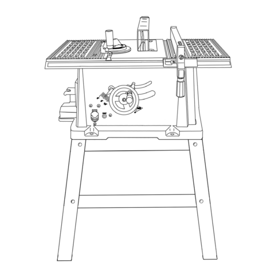
10" BENCH TABLE SAW
WITH STAND
Model # BTS10BW
Item #53433
CAUTION – FOR YOUR OWN SAFETY
READ YOUR OWNER'S MANUAL THROUGH COMPLETELY AND CAREFULLY BEFORE
ATTEMPTING TO SET-UP OR OPERATE YOUR NEW POWER TOOL.
ALL OPERATORS OF THIS EQUIPMENT SHOULD READ AND UNDERSTAND ALL SAFETY
RULES PRINTED ON THE MACHINE AND THIS OWNERS MANUAL BEFORE USE.
Your new Power Tool is a well built, carefully inspected versatile machine, capable of giving you
many years of dependable service. Your power tool comes complete in one carton with a minimum
of first assembly and setup required by you. When unpacking, be sure to check all packages and
packing material for loose parts before discarding.
NOTICE: On the nameplate of your machine you will find the serial number and MFG date code of
your unit. Please record these numbers on this manual cover for future service reference.
SERIAL #
MFG. DATE #
PURCHASE DATE:
.
POWER TOOL SPECIALISTS, INC E.WINDSOR,CT 06088 PRINTED IN CHINA
www.tradesman-rexon.com
1-800-243-5114
Advertisement
Table of Contents

Related Manuals for Tradesman BTS10BW


Summary of Contents for Tradesman BTS10BW
- Page 1 TRADESMAN ® 10” BENCH TABLE SAW WITH STAND Model # BTS10BW Item #53433 CAUTION – FOR YOUR OWN SAFETY READ YOUR OWNER’S MANUAL THROUGH COMPLETELY AND CAREFULLY BEFORE ATTEMPTING TO SET-UP OR OPERATE YOUR NEW POWER TOOL. ALL OPERATORS OF THIS EQUIPMENT SHOULD READ AND UNDERSTAND ALL SAFETY RULES PRINTED ON THE MACHINE AND THIS OWNERS MANUAL BEFORE USE.
-
Page 2: Table Of Contents
TABLE OF CONTENTS SECTION PAGE SECTION PAGE Product Specifications ……………………. Adjustments ……………………………... 15 – 19 Power Tool Safety ..………………………. Operation ………………………………... 20 – 24 Table Saw Safety …………………………. Blade Selection …………………………. Electrical Requirements & Safety ………... Maintenance …………………………….. Accessories & Attachments ………………. Trouble Shooting ……………………….. -
Page 3: Power Tool Safety
POWER TOOL SAFETY CAUTION Before using your table saw, it is critical that you read and understand these safety rules. Failure to follow these rules could result in serious injury or damage to the table saw. 14. USE ONLY RECOMMENDED ACCESSORIES. Good safety practices are a combination of common sense, Consult the Owner’s Manual for recommended staying alert and understanding how to use your power tool. -
Page 4: Table Saw Safety
TABLE SAW SAFETY 1. ALWAYS USE SAW BLADE GUARD, splitter and anti- 12. PROVIDE ADEQUATE SUPPORT to the rear and the kickback pawls for every through sawing operation. sides of the saw table for long or wide workpieces. Through-sawing operations are those in which the blade cuts completely through the workpiece when ripping or 13. -
Page 5: Electrical Requirements & Safety
ELECTRICAL REQUIREMENTS AND SAFETY POWER SUPPLY REQUIREMENTS GROUNDING INSTRUCTIONS CAUTION To avoid electrical hazards, fire hazards or damage to the IN THE EVENT OF A MALFUNCTION OR BREAKDOWN, table saw, use proper circuit protection. Always use a grounding provides a path of least resistance for electric current separate electrical circuit for your tools. -
Page 6: Accessories & Attachments
Do not modify this saw or use accessories not If any parts are missing, do not attempt to assemble the recommended by Tradesman. saw, plug in the power cord or turn the switch ON until the missing parts are obtained and correctly installed. -
Page 7: Carton Contents
CARTON CONTENTS... -
Page 8: Know Your Table Saw
KNOW YOUR TABLE SAW Rip Fence Blade Guard Table Insert Miter Guage Table Blade Tilt Pointer Bevel Locking Knob Blade Tilt Scale Blade Elevation Tilting Handwheel ON/OFF Switch Overload Reset Switch Anti-Kickback Pawls Blade Splitter Splitter Bracket Mounting Holes... -
Page 9: Table Saw Glossary
TABLE SAW GLOSSARY ANTI-KICKBACK PAWLS – Prevents the workpiece from OVERLOAD RESET SWITCH – Resets the thermocouple and being kicked upward or back toward the front of the table saw provides a way to restart the saw motor if it overloads or by the spinning blade. -
Page 10: Assembly
ASSEMBLY Estimated Assembly Time 40~60 minutes Assemble table saw to stand 1. Place protective corrugated or old blanket on floor to ASSEMBLE STAND protect the saw table surface. Unpack all parts and group by type and size (see Fig. 1). 2. - Page 11 ASSEMBLY Fig. 4 FASTEN SAW TO STAND 1. LOCATE MOUNTING HOLES IN SAW BASE This saw MUST be properly secured to a sturdy workbench, stand or cabinet. Use the four ” holes already provided in the saw base. The front two holes (1) are shown in Fig. 3. There are two additional holes in the rear of the saw base.
- Page 12 ASSEMBLY CAUTION INSTALL BLADE TO ARBOR INSTALL BLADE TO ARBOR – Cont’d MAKE SURE THE SAW IS DISCONNECTED FROM THE POWER SOURCE WHEN INSTALLING THE BLADE. Remove the table insert (1) by removing the 2 screws (2 & 3) that hold it in place (see Fig. 7). NOTE: Be careful not to lose the rubber washer that is on the back screw (3) beneath the insert.
- Page 13 ASSEMBLY ASSEMBLE BLADE GUARD AND SPLITTER ASSEMBLE BLADE GUARD AND SPLITTER – Cont’d CAUTION MAKE SURE THE SAW IS DISCONNECTED FROM THE POWER SOURCE WHEN INSTALLING THE 2. Holding the blade guard arm (9) up and using a straight BLADE GUARD AND SPLITTER ASSEMBLIES. edge (11), ensure the splitter (10) is aligned with the saw blade (Fig.
-
Page 14: Miter Gauge Adjustment
ADJUSTMENTS MITER GAUGE ADJUSTMENT RIP FENCE ADJUSTMENT 1. To check the miter gauge, loosen clamp knob (1) to allow 1. To move the rip fence (1) along the table, lift the fence miter body (3) to rotate freely (see Fig. 13). Position the locking handle (2) and slide the fence to the desired miter body so the pointer (2) points to 90 on the... - Page 15 ADJUSTMENTS BLADE TILTING MECHANISM BLADE RAISING AND LOWERING The saw blade can be tilted two different ways. To raise the saw blade, turn handwheel (1) COUNTER CLOCKWISE (see Fig. 16). To lower the blade, turn the RAPID BLADE TILTING handwheel CLOCKWISE.. Loosen blade tilting locking knob (2) (see Fig.
- Page 16 ADJUSTMENTS ADJUST BLADE PARALLEL TO CHECKING INITIAL ADJUSTMENT – cont’d MITER GAUGE GROOVE This adjustment was made at the factory, but it can be rechecked and adjusted if necessary. CAUTION To prevent personal injury: • Always disconnect plug from the power source when making any adjustments.
- Page 17 ADJUSTMENTS ADJUST BLADE PARALLEL TO Re-mount saw blade on the table saw and tighten arbor MITER GAUGE GROOVE Nut. TOOLS REQUIRED While standing at the rear of the saw, use a medium size • 10mm open end or 10mm combination wrench flat blade screwdriver and gently pry the rear of the blade •...
-
Page 18: Bevel Pointer
ADJUSTMENTS BEVEL STOP (VERTICAL) BEVEL STOP 1. Raise the blade fully by rotating the handwheel counter 1. Raise the blade fully by rotating the handwheel counter clockwise until it stops. clockwise until it stops. 2. Loosen bevel angle locking knob. 2. -
Page 19: Operation
OPERATION SAW SWITCH CAUTION The switch (2) is located on the front panel of the saw base (see Fig. 22). To turn the saw ON move the switch to the up Have you read “POWER TOOL SAFETY” and position. To turn the saw OFF move the switch to the down “TABLE SAW SAFETY”... -
Page 20: Bevel Ripping
OPERATION RIPPING – cont’d RIPPING – cont’d 7. The push stick should always be used when the ripped workpiece is 2” or narrower. 3. Hold the workpiece flat on the table and against the fence. Keep the workpiece about 1” back from the blade. 8. -
Page 21: Bevel Crosscutting
OPERATION CROSSCUTTING BEVEL CROSSCUTTING CAUTION This operation is the same as crosscutting except the bevel To prevent serious injury: angle is set to an angle other than 0 • Do not allow familiarity gained from frequent use of 1. Adjust the blade (1) to the desired angle and tighten the your table saw to cause careless mistakes. -
Page 22: Miter Cuts
OPERATION MITER CUTS DADO CUTS This cutting operation is the same as crosscutting except the 1. Unplug the power cord before removing and/or installing mitre gauge is locked at an angle other than 90 dado blades. Set the miter gauge to the desired angle (see Fig. 27). 2. -
Page 23: Blade Selection
OPERATION & BLADE SELECTION USING WOOD FACING ON THE RIP FENCE BLADE SELECTION - cont’d When performing some special cutting operations, add a wood Smaller diameter blades may be used, while they will result in facing (1) to either side of the rip fence (2) (see Fig. 30). a reduced cutting depth, their use will increase the output of the motor. -
Page 24: Maintenance
Place a small amount of dry lubricant such as graphite or silicone on the screw rod (1) at the thrust washer (5). Do not by a trained repair technician. Contact Tradesman Specialists for your nearest Authorized Service Center. Use oil threads of screw rod. The screw rod must be kept clean and only identical replacement parts. -
Page 25: Troubleshooting
TROUBLESHOOTING CAUTION To avoid injury from an accidental start, turn the switch OFF and always remove the plug from the power source before making any adjustments. Consult your local Authorized Service Center if for any reason the motor will not run. SYMPTOM POSSIBLE CAUSES CORRECTIVE ACTION... -
Page 26: Part List
φ1/4" 0JAA WASHER 28KQ PARALLEL BRACKET ASS'Y φ8 0JAE EXTERNAL TOOTH LOCK WASHER 28NL ROCKER SWITCH φ4 0JC9 SPRING PIN 3-18 292S CAUTION LABEL 0JCC SPRING PIN 4-22 293W TRADE-MARK LABEL 0JCR SPRING PIN 8-90 296R BLADE TRADESMAN 0JE7 C-RING... - Page 28 MOTOR PART LIST I.D. Description Size 0HV5 BALL BEARING 0XH9 NEEDLE BEARING 0JAL EXT.TOOTH LOCK WASHER φ4 0JEE C-RING A-17 0JFY PARALLEL KEY 4×4-12 0JX3 HEX. SOC. SET SCREW M5*0.8-8 0K3A CR.RE. PAN HD. SCREW & WASHER M5*0.8-30 0K5V CR.-RE. COUND.HD.SCREW M4×0.7-8 0KCP CR.-RE.PAN HD.TAPPING SCREW &...
- Page 29 MOTOR DIAGRAM...
- Page 30 PART LIST I.D. Description Size 2003 BOTTOM SUPPORT BRACKET (LONG) 2007 0KRR SERRATED TOOTHED HEXAGON FLANGE NUT M8*1.25,T=7.5 0KJ7 CAP HD. SQ.NECK BOLT M8*1.25-16 0JPP HEX. HD. BOLT M8*1.25-30 0J4F FLAT WASHER φ8X16-2.5 2005 UPPER SUPPORT (LONG) 2004 BOTTOM SUPPORT BRACKET 2006 UPPER SUPPORT (SHORT) 093B...
Need help?
Do you have a question about the BTS10BW and is the answer not in the manual?
Questions and answers