Table of Contents
Advertisement
TRADESMAN
®
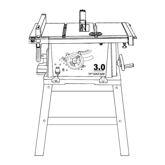
10" TABLE SAW WITH STAND
& EXTENSION WING
Model # BTS10W4
Item #53006
CAUTION – FOR YOUR OWN SAFETY
READ YOUR OWNER'S MANUAL THROUGH COMPLETELY AND CAREFULLY BEFORE
ATTEMPTING TO SET-UP OR OPERATE YOUR NEW POWER TOOL.
ALL OPERATORS OF THIS EQUIPMENT SHOULD READ AND UNDERSTAND ALL SAFETY RULES
PRINTED ON THE MACHINE AND THIS OWNERS MANUAL BEFORE USE.
Your new Power Tool is a well built, carefully inspected versatile machine, capable of giving
you many years of dependable service. Your power tool comes complete in one carton with a
minimum of first assembly and setup required by you. When unpacking, be sure to check all
packages and packing material for loose parts before discarding.
NOTICE: On the nameplate of your machine you will find the serial number and MFG date
code of your unit. Please record these numbers on this manual cover for future service
reference.
SERIAL #
MFG. DATE #
PURCHASE DATE:
.
POWER TOOL SPECIALISTS,INC
E.WINDSOR,CT 06088 PRINTED IN TAIWAN
www.tradesman-rexon.com
1-800-243-5114
Advertisement
Table of Contents

Subscribe to Our Youtube Channel
Related Manuals for Tradesman BTS10W4


Summary of Contents for Tradesman BTS10W4
- Page 1 TRADESMAN ® 10” TABLE SAW WITH STAND & EXTENSION WING Model # BTS10W4 Item #53006 CAUTION – FOR YOUR OWN SAFETY READ YOUR OWNER’S MANUAL THROUGH COMPLETELY AND CAREFULLY BEFORE ATTEMPTING TO SET-UP OR OPERATE YOUR NEW POWER TOOL. ALL OPERATORS OF THIS EQUIPMENT SHOULD READ AND UNDERSTAND ALL SAFETY RULES PRINTED ON THE MACHINE AND THIS OWNERS MANUAL BEFORE USE.
-
Page 2: Table Of Contents
TABLE OF CONTENTS SECTION PAGE SECTION PAGE Product Specifications ………………….. Know Your Table Saw..………………… Power Tool Safety ..…………………….. Table Saw Glossary……….…………….. Table Saw Safety………………………... Assembly and Adjustments……………… Electrical Requirements and Safety…… Operation…. …………………………….. Pre Assembly………….. Maintenance…………...………………..Tools Needed For Assembly..………….. Troubleshooting Guide…………….….. -
Page 3: Power Tool Safety
POWER TOOL SAFETY CAUTION! Before using your table saw, it is critical that you read and understand these safety rules. Failure to follow these rules could result in serious injury or damage to the table saw. Good safety practices are a combination of common sense, 14. -
Page 4: Table Saw Safety
TABLE SAW SAFETY 1. ALWAYS USE SAW BLADE GUARD, splitter and anti- 12. PROVIDE ADEQUATE SUPPORT to the rear and the kickback pawls for every through sawing operation. sides of the saw table for long or wide workpieces. Through sawing operations are those in which the blade cuts completely through the workpiece when ripping or 13. -
Page 5: Electrical Requirements And Safety
ELECTRICAL REQUIREMENTS AND SAFETY POWER SUPPLY REQUIREMENTS GROUNDING INSTRUCTIONS CAUTION! IN THE EVENT OF A MALFUNCTION OR BREAKDOWN, grounding provides a path of least resistance for electric current To avoid electrical hazards, fire hazards or damage to the table and reduces the risk of electric shock. This saw is equipped saw, use proper circuit protection. -
Page 6: Pre Assembly
Do not modify this saw or use accessories not If any parts are missing, do not attempt to assemble the recommended by Tradesman. saw, plug in the power cord or turn the switch ON until the missing parts are obtained and correctly installed. -
Page 7: Carton Contents
CARTON CONTENTS... -
Page 8: Know Your Table Saw
KNOW YOUR TABLE SAW Side Table Blade guard Table insert Table Rip fence Extension Miter gauge Extension Fence Table Blade bevel extension lock knob lock handles Blade bevel handwheel Blade bevel scale On-Off switch with key Blade elevation handwheel Mounting holes Overload reset switch Kickback pawls Blade... -
Page 9: Table Saw Glossary
TABLE SAW GLOSSARY ANTI-KICKBACK PAWLS – Prevents the workpiece from MITER CUT – An angle cut made across the width of the being kicked upward or back toward the front of the table saw workpiece. by the spinning blade. MITER GAUGE – A guide used for crosscutting operations that slides in the table top channels (grooves) located on either ARBOR –... -
Page 10: Assembly And Adjustments
ASSEMBLY AND ADJUSTMENTS Estimated Assembly Time 40~60 minutes ASSEMBLE TABLE SAW TO STAND (Fig. 1, 2) 1. Place protective corrugated or old blanket on floor to protect ASSEMBLE STAND (Fig. 1) the saw table surface. 1. Unpack all parts and group by type and size (Fig. 1). Refer to 2. - Page 11 ASSEMBLY BLADE RAISING HANDWHEEL (FIG. 5, 6) SAW MOUNTED TO WORK SURFACE (FIG. 3) 1. Attach the handwheel (1) to the elevation screw (2) at the 1. If the leg set will not be used, the saw must be properly front of the saw.
- Page 12 ASSEMBLY RIP FENCE (FIG. 7) 2. Raise the blade arbor (4) to the maximum height by turning 1. Thread the fence handle (1) into the cam hole (2) the blade raising handwheel counterclockwise. until tight. 3. Place the open-end wrench jaws on the flats of the saw arbor 2.
- Page 13 ASSEMBLY BLADE GUARD ASSEMBLY (FIG. 11, 12, 13) CAUTION! 1. Set the blade to maximum height and the tilt to zero degrees Improper splitter alignment can cause “kickback” and on the bevel scale with the hand wheels. Lock the blade lock serious injury.
- Page 14 ADJUSTMENTS To avoid injury from an accidental start, make sure RIP FENCE ADJUSTMENT (FIG. 18) the switch is in the OFF position and the plug is not 1. The fence (1) is moved by lifting up on the handle (2) connected to the power source, before making any and sliding the fence to the desired location.
- Page 15 ADJUSTMENTS CAUTION! To avoid injury from an accidental start, make sure the BLADE TILT POINTER switch is in the OFF position and the plug is not 1. When the blade is positioned at 90°, adjust the blade connected to the power source outlet. tilt pointer to read 0°...
- Page 16 ADJUSTMENTS Additional blade adjustments (FIG. 23) 1. If the front and rear measurements are not the same, remove the combination square and loosen the four adjusting screws using a 4mm hex key (1) on the top of the table about a half turn.
-
Page 17: Operation
OPERATION OVERLOAD PROTECTION (FIG. 25) RAISE THE BLADE (FIG. 24) This saw has a reset overload relay button (3) that To raise or lower the blade, turn the blade elevation will restart the motor after it shuts off due to overloading or handwheel (1) to the desired blade height, and then tighten low voltage. - Page 18 OPERATION CUTTING OPERATIONS There are two basic types of cuts: ripping and crosscutting. Fig. 27 Ripping is cutting along the length and the grain of the workpiece. Crosscutting is cutting either across the width or across the grain of the workpiece. Neither ripping nor crosscutting may be done safely freehand.
- Page 19 OPERATION BEVEL RIPPING This cut is the same as ripped except the blade bevel angle is Fig. 29 set to an angle other than “0”. CAUTION! Cut only with the workpiece and the fence on the right side of the blade. RIPPING SMALL PIECES CAUTION! Avoid injury from the blade contact.
- Page 20 OPERATION COMPOUND MITER CROSSCUTTING (FIG. 31) Fig. 33 This sawing operation is combining a miter angle with a bevel angle. 1. Set the miter gauge (3) to the desired angle. Use only the left side groove (2). 2. Set the blade (1) bevel to the desired angle. 3.
-
Page 21: Maintenance
MAINTENANCE MAINTAINING YOUR TABLE SAW Fig. 35 GENERAL MAINTENANCE CAUTION! For your own safety, turn the switch OFF and remove the switch key. Remove the plug from the power source outlet before maintaining or lubricating your saw. 1. Clean out all sawdust that has accumulated inside the saw cabinet and the motor. -
Page 22: Troubleshooting Guide
TROUBLESHOOTING GUIDE CAUTION! To avoid injury from an accidental start, turn the switch OFF and always remove the plug from the power source before making any adjustments. ● Consult your local service center if for any reason the motor will not run. SYMPTOM POSSIBLE CAUSES CORRECTIVE ACTION... -
Page 23: Push Stick Pattern
PUSH STICK PLAN PUSH STICK CONSTRUCTION • This is a full-size drawing (actual size) • Use good quality plywood or solid wood • Use ½” or ¾” material • Push stick MUST be thinner than the width of material being cut Drill Hole For Hanging Notch To... -
Page 24: Parts List
PARTS I.D. Description Size I.D. Description Size 2008 EXTENTION WING 0K8C CR. RE.COUNT HD. TAPPING SCREW M4*18-10 09JK WRENCH HEX. 0K8E CR. RE.COUNT HD. TAPPING SCREW M5*16-12 0B22 HEIGHT REGULATING BOLT 0K91 CR. RE. TRUSS HD. TAPPING SCREW M4*16-12 0B23 SADDLE 0KA4 CR.RE. - Page 26 MOTOR PARTS LIST I.D. NO. DESCRIPTION SIZE 1502 FIELD ASS'Y 1503 ARBOR SHAFT 0HV5 BALL BEARING 6204LLU 0HX9 NEEDLE BEARING φ4 0JAL EXT.TOOTH LOCK WASHER 0JEE C-RING 0JFY PARALLEL KEY 0JX3 HEX. SOC. SET SCREW M5X0.8-8 0K3A CR.RE. PAN HD. SCREW & WASHER M5X0.8-30 0K5V CR.-RE.
- Page 27 MOTOR DIAGRAM...
- Page 28 PARTS I.D. Description Size 2003 BOTTOM SUPPORT BRACKET (LONG) 2007 0KRR SERRATED TOOTHED HEXAGON FLANGE NUT M8*1.25,T=7.5 0KJ7 CAP HD. SQ.NECK BOLT M8*1.25-16 0JPP HEX. HD. BOLT M8*1.25-30 0J4F FLAT WASHER φ8X16-2.5 2005 UPPER SUPPORT (LONG) 2004 BOTTOM SUPPORT BRACKET 2006 UPPER SUPPORT (SHORT) 093B...
Need help?
Do you have a question about the BTS10W4 and is the answer not in the manual?
Questions and answers