
Related Manuals for Mircom FX-3500


Summary of Contents for Mircom FX-3500
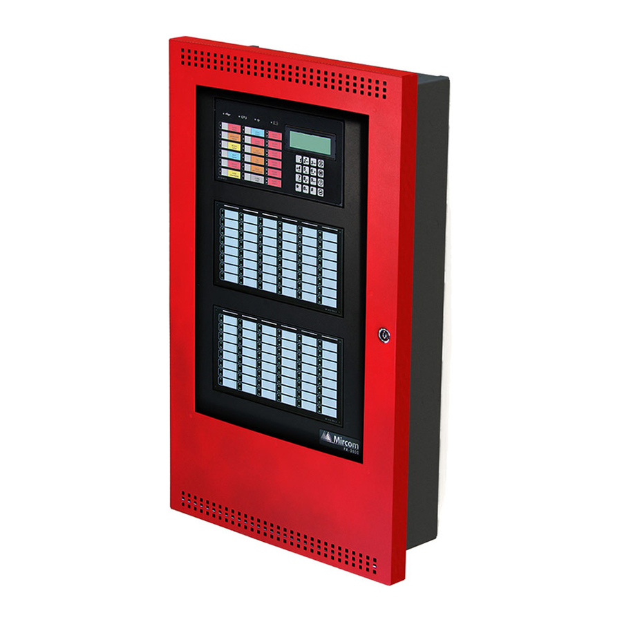
- Page 1 FX-3500 Fire Alarm Control Panel Installation and Operation Manual LT-1083 Rev.2.1 December 2013 For the latest compatability information visit www.mircom.com/deviceguide...
-
Page 3: Table Of Contents
Industry Canada and FCC Notice Notice for all FX-3500 Series Built-In UDACTs Sold in Canada ........Industry Canada Notice ....................Notice for all FX-3500 Series Built-in UDACTs Sold in the U.S.A......... FCC Notice ........................Introduction The FX-3500 Addressable Fire Alarm Control Panel ............. - Page 4 Table of Contents 5.2.1 Alarm Input (Non-Verified) ..................... 5.2.2 Supervisory Inputs ......................5.2.3 Building/Property Safety Input ..................5.2.4 Priority Alarm ........................5.2.5 Trouble-Only Input ......................5.2.6 Waterflow Alarm Input ....................5.2.7 System Status Correlations .................... 5.2.8 Audible Walktest ......................5.2.9 Silent Test ........................
- Page 5 Table of Contents 5.11.13 Exit ..........................Indication & Controls Indication and Controls ....................LCD Display ........................6.2.1 Numeric Keypad and Cursor Buttons ................Common LED Indicators and Control Buttons ............... 6.3.1 Flash Rates ........................Wiring Wiring Tables ......................... 7.1.1 Addressable Loop Wiring Maximums ................7.1.2 RS-485 Wiring to Annunciators and other Devices ............
- Page 6 11.0 Appendix D - Reporting 11.1 Ademco Contact-ID FX-3500 Series Event Codes ............11.2 Security Industries Association SIA Format Protocol FX-3500 Series Event Codes ..12.0 Appendix E - Specifications And Features 12.1 FX-3500 Fire Alarm Control Panel ................. 12.2 FX-3500 System Module and Annunciator Specifications ..........
- Page 7 Figure 18 RTI-1 Common Remote Trouble Indicator Wiring ............Figure 19 Wiring the Dialer ......................Figure 20 Connecting an FX-3500 FACP to a DCS Surguard System Receiver ......Figure 21 Wiring the PR-300 Polarity Reversal and City Tie Module ..........
- Page 8 ULC Intelligent Modules ....................Table 40 ULC Two-Wire Smoke Detectors ................... Table 41 Contact-ID Event Codes ....................Table 42 SIA-DCS Event Codes ....................Table 43 FX-3500 Specifications ....................Table 44 FX-3500 System Modules and Annunciator Specifications ........... Table 45 Recommended Batteries ....................
-
Page 9: Industry Canada And Fcc Notice
Industry Canada and FCC Notice Notice for all FX-3500 Series Built-In UDACTs Sold in Canada Mircom's FX-3500 SERIES BUILT-IN UDACT Communicator described in this manual is listed by Underwriters Laboratories Canada (ULC) for use in slave application under Standard ULC- S527 (Standard for Control Units for Fire Alarm Systems) and ULC-S559 (Equipment for Fire Signal Receiving Centres and Systems). -
Page 10: Fcc Notice
In the event repairs are ever needed on the Communicator, they should be performed by Mircom Technologies Ltd. or an authorized representative of Mircom Technologies Ltd. For information contact Mircom Technologies Ltd. -
Page 11: Introduction
Semi-flush or surface mountable enclosures for retrofits and new installations. Note: Installation of the FX-3500 Series Fire Alarm Control panel should be in accordance with Canadian Electrical Code Part 1, ULC-S524 installation of Fire Alarm System; or National Electrical Code NFPA 70 and NFPA 72. Final... -
Page 12: General Notes
30 (up to 64) LED display and to facilitate the bypassing of inputs and outputs. Display Points The FX-3500 LCD display annunciates the status of the system and connected devices. There are up to two (2) RAX-1048TZDS Display Adder Module Display points that may be configured to assign LEDs to groups of inputs or outputs. -
Page 13: Contact Us
For General Inquiries, Customer Service and Technical Support you can contact us Monday to Friday 8:00 A.M. to 5:00 P.M. E.S.T. 2.3.1 General Inquiries Toll Free 1-888-660-4655 (North America Only) Local 905-660-4655 Email mail@mircom.com 2.3.2 Customer Service Toll Free 1-888-MIRCOM5 (North America Only) Local 905-695-3535 Toll Free Fax 1-888-660-4113 (North America Only) -
Page 14: Fx-3500 Overview
FX-3500 Overview FX-3500 Overview This chapter lists all the possible components of an FX-3500 system. FX-3500 Fire Alarm Control Panel Models All FX-3500 Fire Alarm Control Panels have the following features: • Main Board, Power Supply and Backbox. • Multi-zone fire alarm control panel •... -
Page 15: Fx-3500 System Components
FX-3500 Overview FX-3500 System Components The following table describes the components of the FX-3500. Table 1 FX-3500 System Components Model Description MAM-3500 Main Display Visual Indicator Test DOX-1024DS White enclosure door DOX-1024DSR Red enclosure door ALC-636 636 Point Dual Loop Adder. - Page 16 FX-3500 Overview Table 1 FX-3500 System Components (Continued) Model Description Power Supply Interface Board use for powering PCS-100 GS3060 Universal Wireless Alarm Communicator. Smart Relay Module with White Enclosure. SRM-312W Can support up to 12 relays. Smart Relay Module with Red Enclosure.
- Page 17 FX-3500 Overview Table 1 FX-3500 System Components (Continued) Model Description 2 3 4 9 10 11 MGD-32 Graphic Annunciator. JW15 8 7 6 14 13 12 RAX-LCD-LITE Remote Annunciator with 4-line LCD Display. 2 3 4 9 10 11 AGD-048 Graphic Annunciator Adder Driver Board.
- Page 18 FX-3500 Overview Table 1 FX-3500 System Components (Continued) Model Description BB-1002R Red Enclosure for two annunciators. BB-1003 White Enclosure for three annunciators. BB-1003R Red Enclosure for three annunciators. BB-1008 Enclosure for eight annunciators. BB-1008R Red Enclosure for eight annunciators. BB-1012...
- Page 19 FX-3500 Overview Table 1 FX-3500 System Components (Continued) Model Description BB-1012R Red Enclosure for twelve annunciators. MP-300 End of line resistor plate. 3K9. BC-160 External Battery Cabinet. INX-10A Intelligent NAC Expander Panel.
-
Page 20: Devices
FX-3500 Overview 3.2.1 Devices The following tables lists all the devices available for the FX-3500. Table 2 Advanced Protocol Detectors Advanced Protocol Detectors MIX-1251AP Advanced Protocol Ion Smoke Detector MIX-1251APA Advanced Protocol Ion Smoke Detector ULC MIX-2251AP Advanced Protocol Photo Smoke Detector... -
Page 21: Table 4 Advanced Protocol Manual Stations
FX-3500 Overview Table 4 Advanced Protocol Manual Stations Advanced Protocol Manual Stations MS-401AP Addressable Single Stage Manual Station ULC MS-402AP Addressable Two Stage Manual Station ULC MS-701AP Addressable Single Stage Single Action Station ULC MS-701APU Addressable Single Stage Single Action Station... -
Page 22: Table 7 Clip Detectors
FX-3500 Overview Table 7 CLIP Detectors Intelligent Detectors MIX-1251B Intelligent Low Profile Ionization Smoke Sensor MIX-1251BA Intelligent Low Profile Ionization Smoke Sensor ULC MIX-2251B Intelligent Low Profile Photoelectronic Smoke Sensor MIX-2251BA Intelligent Low Profile Photoelectronic Smoke Sensor ULC Intelligent Low Profile Photoelectronic Smoke Sensor c/w 135°F Fixed Temp. -
Page 23: Installation
Installation Installation This chapter describes the installation of the FX-3500. BBX-1024DS and BBX-1024DSR Mechanical Installation The BBX-1024DS and BBX-1024DSR are suitable for flush or surface mounting, and have a built-in trim ring. Dimensions of Enclosure (minus built in trim ring) 14.5”... -
Page 24: Installation Tips
Attention: DO NOT install cable through bottom of the box. This space is reserved for Batteries. Installing Adder Modules The FX-3500 Series Fire Alarm panels are shipped pre-assembled with all main components and boards. Adder modules are not preinstalled. The following items can be installed in the field: •... -
Page 25: Figure 3 Main Board With All Adder Modules Installed
Installation TR-063A Transformer Barrier Terminal Block FX-3500 Main Board Rectifier Bridge ALC-636 Dual Loop Adder MD-1011 Power Supply Board PR-300 Polarity Reversal And City Tie Module Note: The PCS-100 mounts in the same position as the PR-300. Figure 3 Main Board with all Adder Modules Installed... -
Page 26: Figure 4 Port And Jumper Locations On Main Board
Installation JW11 JW10 Buzzer JW12 Figure 4 Port and Jumper Locations on Main Board... -
Page 27: Table 9 Main Board Connectors And Jumper
Installation Table 9 Main Board Connectors and Jumper Connector/ Description Jumper To Power Supply To Power Supply Ribbon Cable connects to P4 of MAM-3500 To PC Configurator To PR-300 To Printer To ALC-636 Loop Adder Factory Use Only USB Port Future Use Must be ON - Allows Configuration Connection Must be ON - Annunciator End of Line... -
Page 28: Installing The Pr-300 Polarity Reversal And City Tie Module
Table 10 PR-300 Polarity Reversal and City Tie Module Connectors and Jumpers Item Setting Connect cable to P8 on the Main Board of the FX-3500 Not used. Keep jumper intact. Note: If using a PR-300 remember to remove JW7 on the main board. For the location of JW7 on the main board see Figure 3. -
Page 29: Figure 6 Installing The Alc-636 Dual Loop Adder
Installation ALC-636 Mounted on hex spacer with four screws provided Figure 6 Installing the ALC-636 Dual Loop Adder Table 11 ALC-636 Dual Loop Adder Connectors and Jumpers Item Setting Connect cable to P10 on the Main Board of the FX-3500. -
Page 30: Installing The Rax-1048Tzds Display Adder Module
Installation 4.4.1 Installing the RAX-1048TZDS Display Adder Module The FX-3500 can add a maximum of two RAX-1048TZDS Display Adder Module. No jumpers or other physical configuration steps are required to install the RAX-1048TZDS Display Adder Modules. To Install the RAX-1048TZDS Display Adder Module 1. -
Page 31: Operation
DO NOT connect more than 25 devices to a single isolator or between isolators. • The FX-3500 FACP will test the sensitivity of a single sensor address every 4 minutes. Each address will be tested once in approximately every 11 hours. -
Page 32: Supervision Of Devices
Figure 7 FX-3500 Configurator Date and Time Settings The panel can provide up to 280mA of current to the devices on the loop at normal standby. For device currents see Appendix F - Battery Calculations on page 100. -
Page 33: Drift Compensation
Operation For further information refer to the device Installation Instructions and other documentation provided with the addressable devices, bases, and isolators. 5.1.4 Drift Compensation Drift Compensation is built into AP devices and CLIP devices Models MIX-2251TMB and MIX- 7251B, and is not performed by the panel. Drift Compensation is not provided for other CLIP devices. -
Page 34: Alarm Input (Non-Verified)
Operation Table 13 Configurable Input Types (Continued) Device Types Description Detectors As listed in located in Dual Mini Modules Mini Monitor Module Input Type Configurator Section number Zone Module Monitor Module Acknowledge General Ack GA 5.2.7 Alarm Audible Walktest Audible Walktest 5.2.8 Silent Test Silent Test... -
Page 35: Building/Property Safety Input
Operation • Restoring the non-latching supervisory input returns all outputs correlated to the input, that are not correlated to another active input, to normal. • Zone display indicators update announcing the input is no longer active and removes the message from the shared display common queue. •... -
Page 36: Waterflow Alarm Input
Operation • May also be programmed to relay, signal, and strobe outputs. Note: Trouble conditions initiated as a result of a trouble-only input activating is separate from the circuit or device supervision trouble. 5.2.6 Waterflow Alarm Input Waterflow inputs are sampled every second. 10 samples in alarm in any given 15 second period confirms the alarm condition. -
Page 37: Manual Day/Night
Operation 5.2.10 Manual Day/Night Configures (mini) monitor modules for manual day/night alarm thresholds. For more information on alarm thresholds see 5.1.3 Alarm Conditions. 5.2.11 Auto Day/Night Configures (mini) monitor modules for auto day/night alarm thresholds. For more information on alarm thresholds see 5.1.3 Alarm Conditions. 5.2.12 Verified Alarm Input Un-bypassed verified alarm inputs entering into alarm are verified over a period of time to determine if the alarm condition is valid. -
Page 38: Signal Output
Synchronized strobes and strobe/horn models of the following manufacturers are supported: System Sensor, Wheelock, Secutron, and Mircom. Note: Silencing of the horn depends on the feature provided by the manufacturer of the horn/strobe combination. -
Page 39: Relay Output
• Wheelock For a complete list of compatible Horn/Strobes see 9.2 FX-3500 Compatible Horn/Strobes. When configured as normal, the output circuit is ON continuously when activated and does not use any sync protocol. When configured as non-silenceable strobes, the strobes cannot be silenced, but the horn can be silenced by pressing the 'signal silence' button. -
Page 40: Single Stage Operation
Operation Single Stage Operation In a single stage system, all alarm inputs are treated in a similar manner. Alarm inputs include any of the following: • Non-verified alarm • Verified alarm • Waterflow alarm • Sprinkler alarm Any of the above alarm inputs activating when the panel is not already in alarm cause the following: •... - Page 41 Operation • Cancels active fire drill. • Common Alarm LED turns ON. • Common Alarm relay activates if Aux disconnect is not active. • The Auto Signal Silence timer activates (if configured). • The Signal Silence Inhibit timer activates (if configured). •...
-
Page 42: Evacuation Codes
California Code 5 seconds on 10 seconds off. 5.7.1 Two Stage Alert Code When configured for Two Stage operation, the FX-3500 FACP uses a pre-configured Alert code that sounds prior to the evacuation code. Alert Code 0.5 second on, 2.5 seconds off. -
Page 43: Enabling Or Disabling The Positive Alarm Sequence
Enabling or Disabling the Positive Alarm Sequence is done using the numeric keypad. For more information on how to use the Numeric Keypad see 6.2.1 Numeric Keypad and Cursor Buttons on page 61. For details on configuring the FACP for PAS see LT-1148 FX-3500 Programming Manual. -
Page 44: Remote Annunciator Operation
Operation Remote Annunciator Operation The FX-3500 System supports the following types of annunciators • RAX-LCD-LITE shared display annunciator. • RAM-3500-LCD shared display annunciator. • Conventional LED/switch annunciators. Both types of annunciators are connected to the panel via the RS-485 serial link. -
Page 45: Conventional Annunciators
Supervised as one of the (maximum) seven permitted annunciators. 5.10 Dialer Operation The FX-3500 is equipped with a built-in dialer. The dialer provides a means to communicate panel status to the remote central monitoring station using two dedicated phone lines. The two standard protocols for communicating with the central monitoring station are supported by this panel are as follows. - Page 46 Operation 1. DC voltage is supervised and if it is detected the dial tone is monitored. 2. If the phone lines are equipped with a house phone with proper connection and is in use the supervision is suspended until the house phone is ON-HOOK again. 3.
-
Page 47: Using The Operation Menu From The Control Panel
Operation 5.11 Using the Operation Menu from the Control Panel Operations of the FX-3500 Addressable Fire Alarm Control Panel can be managed via the Operation Menu on the LCD Shared Display. Accessing the menus is done via the Numeric Keypad and Cursor Buttons. For a complete description of how to use the Numeric Keypad and Cursor Buttons see Numeric Keypad and Cursor Buttons on page 61. -
Page 48: Setting The Time
Operation 5.11.1 Setting the Time Date : Oct 08, 2005 Time : 10:00 PM Sets the current date and time for the panel. Use the ‘#’ key to move the cursor forward and the UP and DOWN key to change the date/time parameters. 5.11.2 Setting the Password Sets the password for all three access levels. -
Page 49: Reports
Operation 5.11.3 Reports Overview Reports can be generated in command mode from the reports menu. Reports can be displayed in a special format on the shared display for the following items: Report Menu 1. Alarm Log 2. Event Log 3. Current levels 4. - Page 50 Operation 3. Current level The current levels report displays device information for each of all eligible devices on the target loop (specified by user) or on all eligible devices on all loops if user specifies target loop as '0'. Eligible devices will be those present in the configuration and also detected as present on the real loops.
- Page 51 AP devices. Since parameter values and addresses are not disclosed to the user, this tool is used to report information to Mircom technical support. If the panel is connected to a printer the user will be prompted to select an output source: - Report To - 1.
-
Page 52: Clear Logs
Operation subaddress, “Parm#” indicates parameter number from the current subaddress, and “Val#” indicates the paramter value. Crt. S/A Parm# Val 5.11.4 Clear Logs Clears the logs stored in the flash memory. Use the UP and DOWN cursor keys to the desired log to be cleared and press the Enter button. -
Page 53: Bypass
Operation Select Test Type 1. Audible Test 2. Silent Test The following message will show the walk test initializing. Initializing Walk test ... While the walk-test is active the following message is displayed on the screen: --Walk test Active -- Alarm :nnn Trbs :mmm where nnn and mmm are continuously updated counts of the number of alarms and troubles which have been recorded during the test (alarms includes all input circuit types tested). - Page 54 Operation Dev Loop # & Addr Loop :__ DevAddr :___ If the device is not bypassed the user is prompted to bypass the circuit. Device not bypassed Bypass ?Y/N After the confirmation, the device is bypassed and the message appears that the device is bypassed.
-
Page 55: Table 16 List Bypass Special Characters
Operation Group Unbypassed 3. Loop The whole loop either conventional or addressable can be bypassed using this option. The user is prompted to enter the loop number to be bypassed. Loop number Loop :__ If the loop is not already bypassed the user is then prompted to bypass the loop. Loop 0 not bypassed Bypass ?Y/N After the confirmation, the loop is bypassed and a bypass confirmation message displays. - Page 56 Operation The message displayed if the current address carries no device is as follows: The following message is displayed to bypass. If the device is already bypassed the message is as follows. If the exclamation is not used, then there will be individual confirmation. At the end of the bypass operation or if the exclamation is used, the message displays: 5.
-
Page 57: Auxiliary Disconnect
Operation At the end of the un-bypass operation or if the exclamation is used, the message displays: 5.11.7 Auxiliary Disconnect The auxiliary disconnect operation is performed by the following the steps below. If the auxiliary relays are connected the user is prompted to disconnect the relays. Aux relays connected Disconnect ?Y/N After the confirmation the auxiliary relays are disconnected and the information message is... -
Page 58: Clear Verify Count
Operation Select mode 1. Daytime 2. Night time After the user selection and information message is displayed that the daytime nighttime mode is updated. Day/night mode updated 5.11.10 Clear Verify Count This operation is used to clear all the verification counts accumulated during the alarm verification process. -
Page 59: Exit
Operation 5.11.13 Exit Exits to the main command menu. -
Page 60: Indication & Controls
• 16 button Numeric Keypad with Cursor buttons • 6 Hazard Zones with 2 LEDs (red and yellow) each Figure 10 displays the LED indicators and the control button on the FX-3500 main board. Visual Indicator Test Figure 10 LED Indicators and Control Buttons The FX-3500 has the ability for 2 additional RAX-1048TZDS. -
Page 61: Numeric Keypad And Cursor Buttons
Indication & Controls Use the cursor buttons on the Numeric Keypad for menu selection and control. For more information see 6.2.1 Numeric Keypad and Cursor Buttons on page 61. 6.2.1 Numeric Keypad and Cursor Buttons Figure 11 Numeric Keypad Table 17 Keypad and Cursor buttons descriptions Description Key 2 (Up cursor) Press this button to move the cursor or scroll up lists in a continuous loop. -
Page 62: Common Led Indicators And Control Buttons
Indication & Controls Common LED Indicators and Control Buttons For complete descriptions of all LED indicators and control buttons see the following table. Table 18 LED Indicators and Control Buttons LED Indicator and Description Control Buttons AC On Indicator Illuminates steady green when the main AC power is within acceptable levels. The LED turns off when the level falls below the power-fail threshold and the panel is switched to standby (battery) power. - Page 63 Indication & Controls Table 18 LED Indicators and Control Buttons (Continued) LED Indicator and Description Control Buttons Trouble Queue Button and Indicator Flashes yellow when any trouble condition is detected on the panel. The buzzer sounds at the slow rate. Pressing the Trouble Queue button allows the user to cycle through and review a list of active Troubles from oldest to most recent.
- Page 64 Indication & Controls Table 18 LED Indicators and Control Buttons (Continued) LED Indicator and Description Control Buttons Automatic Alarm Signal Cancel Button and Indicator Automatic Alarm LED and Indicator are active only when the Panel is configured for PAS. Signal Cancel Flashes yellow at the Fast Flash Rate as the Auto General Alarm Timer is timing.
-
Page 65: Flash Rates
Indication & Controls Table 18 LED Indicators and Control Buttons (Continued) LED Indicator and Description Control Buttons Auxiliary Disconnect Button and Indicator Activating the Auxiliary Disconnect button activates the Auxiliary Disconnect function. The Auxiliary Alarm Relay is always disconnected with this button. The Common Alarm Relay, the Common Supervisory relay and all correlated alarm relays may be disconnected as selected through configuration. -
Page 66: Wiring
Wiring Wiring This chapter describes the proper field wiring for the FX-3500. Wiring Tables 7.1.1 Addressable Loop Wiring Maximums Advanced Protocol and CLIP Devices • Maximum Loop Current = 350 mA • Maximum Loop Resistance = 40 ohms • Maximum Loop Capacitance = 0.5 µF •... -
Page 67: Input Circuits
Maximum Voltage Drop Should Not Exceed 1.67 Volts 7.1.4 Input Circuits If using conventional input circuits in an FX-3500 system MIX-502MAP(A), MIX-502M and CZ-6 Conventional Zone Modules must be used. Table 21 MIX-502MAP(A) Conventional Zone Module Input Circuit Wiring Table... -
Page 68: Wire Routing
Wiring Wire Routing Notes: All external connections are power limited except for the AC connections to the transformer. Transformer connections must be routed separately from all other external connections using their own conduit. All power limited wiring shall be routed through the remaining knockouts. -
Page 69: Addressable Loop Wiring
Wiring Addressable Loop Wiring 7.3.1 Addressable Loop Wiring - Class B or Style 4 ION SMOKE DETECTOR OUTPUT MODULE PHOTO SMOKE DETECTOR PULL STATION HEAT DETECTOR CLASS B WIRING Figure 13 Addressable Loop Wiring - Class B or Style 4 7.3.2 Addressable Loop Wiring - Class A or Style 6 ION SMOKE DETECTOR... -
Page 70: Addressable Loop Wiring - Class A Or Style 7
HEAT DETECTOR Figure 15 Addressable Loop Wiring - Class A or Style 7 NAC Circuit Wiring The FX-3500 supports up to 4 NAC circuits that can be wired as either: • Class B (Style Y) • Class A (Style Z) To supervise each Class B NAC circuit, use a 3.9K End-of-Line resistor. -
Page 71: Nac Circuit - Class B Or Style Y Wiring
Wiring 7.4.1 NAC Circuit – Class B or Style Y Wiring STYLE Y WIRING CIRCUIT - 1 + + - - NAC1 NAC CIRCUITS #2, #3 AND #4 ARE NOT SHOWN. WIRE AS SHOWN ABOVE. BELL STROBE HORN EOL-392 Figure 16 NAC Circuit –... -
Page 72: Ul 864 Rev. 9 Addressable Supervised Output Module Wiring
Wiring 7.4.3 UL 864 Rev. 9 Addressable Supervised Output Module Wiring As per UL864 Rev.9 51.4.3, ensure that a single break, ground or wire-to-wire fault on the installation conductors of a signalling circuit for use with addressable notification appliances or modules shall not affect the operation of more than one notification zone. -
Page 73: Module And Devices Wiring
Wiring Module and Devices Wiring 7.5.1 Dialer Wiring Wire the Dialer to the Public Telephone Switch and premises Telephone as shown in Figure 19. For information on Compatible DACR Receivers see Chapter 8.0 Appendix A - Compatible Receivers. Public Switch Telephone Wiring RJ31X GREEN BROWN... -
Page 74: Connecting To A Dcs Surguard Receiver
SG-Systems Console 2.1 AUX 1 PCS-100 SUR-GARD Printer SYSTEM II Internal IP : X.X.X.X External IP : X.X.X.X Default Gateway : X.X.X.X Sub-Net Mask:X.X.X.X Port #: YYYY (UDP) Figure 20 Connecting an FX-3500 FACP to a DCS Surguard System Receiver... -
Page 75: Polarity Reversal And City Tie Module Wiring
Wiring 7.5.3 PR-300 Polarity Reversal and City Tie Module Wiring Wire the PR-300 Polarity Reversal and City Tie Module successfully as shown in Figure 21. • Plug PR-300 ribbon cable P1 into connector P8 on the Main Fire Alarm Board. •... -
Page 76: Power Supply Wiring
600 volt insulation and proper over current circuit protection that complies with local codes. For FX-3500 Power Supply Electrical Ratings see Table 22 Power Supply Electrical Ratings and for Specifications see Appendix C. Table 22 Power Supply Electrical Ratings... -
Page 77: Supervision Of Auxiliary Supplies
Wiring White/Blue Stripe Blue Black Brown FX-3500 Main Board 240VAC 50Hz 120VAC 60Hz Ribbon Cable Ground Green Black Power Connector – BRIDGE MD-1011 Power Supply Board P5 P6 BLACK BLACK BATTERY BATTERY Figure 22 Main Power Supply Wiring and Connections 7.6.2 Supervision of Auxiliary Supplies... -
Page 78: Figure 23 Supervision Of Auxiliary Supplies
Wiring This filtered circuit is supervised for shorts. A short will: • Disconnect the power until the “RESET” button is pressed. • Generate a trouble signal The circuit must be supervised for opens utilizing the End of Line Relay Model EOLR-1A as shown in Figure 15. -
Page 79: System Checkout
Wiring System Checkout The following are the recommended steps before and during the powering up of the FX-3500. 7.7.1 Before Turning The Power ON 1. To prevent sparking, DO NOT connect the batteries first. Connecting the batteries is only to be done after the system has been powered from the main AC Supply. -
Page 80: Appendix A - Compatible Receivers
Appendix A - Compatible Receivers The dialers that are built into select models of the FX-3500 Fire Alarm Control Panels are compatible with the following Digital Alarm Communicator Receivers (DACR) listed: Table 23 Compatible DACR Receivers DACR Receiver Model Protocols... -
Page 81: Appendix B - Fx-3500 Series Compatible Devices
Appendix B - FX-3500 Series Compatible Devices FX-3500 Series ULI Listed Compatible Devices 9.1.1 ULI Listed Compatible Addressable Devices Table 24 ULI Advanced Protocol Detectors Advanced Protocol Detectors MIX-1251AP Advanced Protocol Ion Smoke Detector MIX-2251AP Advanced Protocol Photo Smoke Detector... -
Page 82: Table 27 Uli Ancillary Modules
Table 27 ULI Ancillary Modules Ancillary Modules CR-6 Six Relay Control Module CZ-6 Six Conventional Zone Interface Module IM-10 Ten Input Monitor Module M500X Fault Isolator Module SC-6 Six Supervised Control Module Table 28 ULI Bases Bases B210LP Intelligent Flanged Mounting Base B224BI Intelligent Isolator Base B224RB... -
Page 83: Table 30 Uli Intelligent Modules
Table 30 ULI Intelligent Modules Intelligent Modules MIX-500DM Intelligent Dual Monitor Module MIX-M500M Intelligent Addressable Monitor Module MIX-M500R Intelligent Addressable Relay Module MIX-M500S Intelligent Addressable Supervised Control Module MIX-M501M Intelligent Addressable Mini-Monitor Module MIX-M502M Intelligent Addressable Interface Module... -
Page 84: Uli Listed Compatible Two-Wire Smoke Detectors
Table 31 ULI Two-Wire Smoke Detectors Make Model / Base Compatibility Rated Standby Maximum # of Identifier Head/Base Current (mA) devices per circuit Mircom Bases MSB-65B, MSB-65B-4, MSB-65B-4R MPD-65P MPD-65P 0.13 Apollo Series 60A Bases 45681-200,-220,-232,-251 Series 65A Bases 45681-255,-256,-257,-258 55000-325 55000-325 0.13... - Page 85 Table 31 ULI Two-Wire Smoke Detectors (Continued) Make Model / Base Compatibility Rated Standby Maximum # of Identifier Head/Base Current (mA) devices per circuit 429CT / (701E, 701U, 702E, 702U) S10A-S00 711U-UT / (701E, 701U, 702E, 702U) S10A-S00 713-5U / (701E, 701U, 702E, 702U) S10A-S00 713-6U / (701E, 701U, 702E, 702U) S10A-S00...
-
Page 86: Fx-3500 Compatible Horn/Strobes
Current (mA) devices per circuit 2WT-B c/w base FX-3500 Compatible Horn/Strobes Table 32 FX-3500 Compatible Horn/Strobes Brand Strobe Model Maximum # of devices per circuit Mircom FHS-240-110 Secutron MRA-HS3-24WW SpectrAlert Wheelock NS-24 MCW-FW Note: The FX-3500 supports “Regulated 24FWR” devices. -
Page 87: Fx-3500 Series Ulc Listed Compatible Devices
FX-3500 Series ULC Listed Compatible Devices 9.3.1 ULC Listed Compatible Addressable Devices Table 33 ULC Advanced Protocol Detectors Advanced Protocol Detectors MIX-1251APA Advanced Protocol Ion Smoke Detector MIX-2251APA Advanced Protocol Photo Smoke Detector ULC MIX-2251TAPA Advanced Protocol Photo Heat Detector ULC... -
Page 88: Table 36 Ulc Ancillary Modules
Table 36 ULC Ancillary Modules Ancillary Modules CR-6A Six Relay Control Module CZ-6A Six Conventional Zone Interface Module ULC IM-10A Ten Input Monitor Module ULC M500XA Fault Isolator Module ULC SC-6A Six Supervised Control Module ULC Table 37 ULC Bases Bases B210LPA Intelligent Flanged Mounting Base ULC... - Page 89 Table 39 ULC Intelligent Modules (Continued) Intelligent Modules MIX-M501MA Intelligent Addressable Mini-Monitor Module ULC MIX-M502MA Intelligent Addressable Interface Module ULC...
-
Page 90: Ulc Listed Two-Wire Smoke Detectors
System Sensor SLR-24/NS4-220 1400A SLR-24/NS6-220 2400A 1451/B401B 2451/B401B 1451A/B401BA 2451A/B401BA 2451THA/B401BA 2400THA 1151A/B110LPA or B401A 2151A/B110LPA or B401A 9.3.3 UL and ULC Listed Supported Non-Synchronous Horn/Strobes Device Mircom Equivalent Part # Amseco Part # Horns/Strobes FHS-240R/FHS-240W SH24W-153075 Strobes FS-240R/FS-240W SL24W-153075... -
Page 91: Appendix C - Manual Panel Configuration
10.0 Appendix C - Manual Panel Configuration COMMAND MENU The command menu is the first menu displayed for command mode. The command menu is divided into four main sub menu categories, the configuration allows full front panel configuration of the system and the operation menu performs certain operations which may not be possible using the common control switches and indicators on the front panel. - Page 92 front panel. Panel Configuration/Features/Auxiliary disconnect, disconnects alarm and supervisory relay Aux Dis Alm&Sv [ ] Enabled If enabled the auxiliary disconnect operation, disconnects alarm and supervisory relays disabled the auxiliary disconnect operation has no affect on the alarm and supervisory relays. Default is disabled. Panel Configuration/Features/Signal silence inhibit timer Sig.sil.
- Page 93 ON steady. This feature applies to the main panel powered output circuits, configured as strobes, only. Note: Once a specific type of strobe is selected, for example Mircom, then only this type of strobe is allowed for the entire system. Panel Configuration/Features/Evacuation code Evac.
-
Page 94: Panel Configuration/2. Address Cfg
This feature configures all addressable loops as Class A if enabled. Panel Configuration/Features/Auto after hours Auto afthrs. [ ] Enabled This feature allows the daytime/nighttime mode to be set automatically if enabled. Panel Configuration/Features/General alarm timer Gen.alm tmr [x] Disabled [ ] 5 min [ ] 10 min [ ] 15 min... -
Page 95: Panel Configuration/4. User Message
______ PANEL CONFIGURATION/4. USER MESSAGE Allows you to edit (change) the FACP Front Panel Message, i.e. “Welcome to Mircom”. PANEL CONFIGURATION/5. LANGUAGE Allows you to select the language of the LCD display. English is the default. To change the language to French, select French in the panel configuration menu, then exit the configuration and then re-enter and select auto default. -
Page 96: Appendix D - Reporting
11.0 Appendix D - Reporting 11.1 Ademco Contact-ID FX-3500 Series Event Codes Table 41 Contact-ID Event Codes Event Description Event Qualifier Code Group # Contact # Family Phone Line #1 trouble detected Trouble New event 1 351 Phone Line #2 trouble detected... -
Page 97: Security Industries Association Sia Format Protocol Fx-3500 Series Event Codes
11.2 Security Industries Association SIA Format Protocol FX-3500 Series Event Codes SIA Format Protocol does not define indicating zone troubles, but lists it as Untyped Zone Trouble/Restore. Table 42 SIA-DCS Event Codes Event Description Event Family Qualifier SIA Event Code Parameter... -
Page 98: Appendix E - Specifications And Features
99 addressable modules per loop. Maximum loop resistance depends on number of devices and device type. For a complete list of compatible devices see 9.0 Appendix B - FX-3500 Series Compatible Devices. Power Limited / 22VDC / 350mA alarm maximum / 0.5 µF Power Limited / 22VDC / 280mA normal standby maximum / 0.5 µF... -
Page 99: Fx-3500 System Module And Annunciator Specifications
Open Circuit Fault 100 K Ohms Short Circuit Fault 0 Ohms 12.2 FX-3500 System Module and Annunciator Specifications Table 44 FX-3500 System Modules and Annunciator Specifications FX-3500 System Modules and Annunciators RAM- Remote Annunciator Standby 70mA / alarm 100mA 3500LCD... -
Page 100: Appendix F - Battery Calculations
For specifications see Appendix C Specifications And Features on page 98. Power Requirements (All currents are in amperes) Total Total Model Number Description Standby Alarm Standby Alarm FX-3500 FX-3500 FACP with Dialer 0.390 0.630 ALC-636 636 Point Dual Loop Adder 0.120 0.200 Remote Annunciator with 4- RAM-3500-LCD 0.070 0.100... -
Page 101: Table 45 Recommended Batteries
Total Alarm Current must be 10 amperes or less. NAC Circuits must not exceed 6 amperes. Battery Selection Battery Size = Multiply (C) by 1.20 to derate battery. See the following table for the recommended Mircom batteries for use with this panel Table 45 Recommended Batteries Battery Model... -
Page 102: Warranty And Warning Information
14.0 Warranty and Warning Information Warning Please Read Carefully Note to End Users.This equipment is subject to terms and conditions of sale as follows: Note to Installers This warning contains vital information. As the only individual in contact with system users, it is your responsibility to bring each item in this warning to the attention of the users of this system. - Page 103 Mircom shall not be liable for any delays, breakdowns, interruptions, loss, destruction, alteration or other problems in the use of a product arising our of, or caused by, the software.
- Page 104 Telephone Lines If telephone lines are used to transmit alarms, they may be out of service or busy for certain periods of time. Also the telephone lines may be compromised by such things as criminal tampering, local construction, storms or earthquakes. Insufficient Time There may be circumstances when the system will operate as intended, yet the occupants will not be protected from the emergency due to their inability to respond to the warnings in a...
-
Page 105: Limited Warranty
Mircom management, no credits will be issued for custom fabricated products or parts or for complete fire alarm system. Mircom will at its sole option, repair or replace parts under warranty. Advance replacements for such items must be purchased. -
Page 106: Disclaimer Of Warranties
(including all implied warranties of merchantability or fitness for a particular purpose) And of all other obligations or liabilities on the part of Mircom neither assumes nor authorizes any other person purporting to act on its behalf to modify or to change this warranty, nor to assume for it any other warranty or liability concerning this product. - Page 108 Telephone: ________________________________________ Manual Signal Silence: _ No(disabled) _ 5 _ 10 _ 15 _ 20 _ 30 minutes System Model: FX-3500 Fire Alarm Control Panel City Tie: Disconnectable _ No _ Yes System Type: Local, Auxiliary (using PR-300), Remote Station (using PR-300), Central Station...
- Page 112 CANADA - Main Office U.S.A TECHNICAL SUPPORT © Mircom 2013 25 Interchange Way 4575 Witmer Industrial Estates North America Printed in Canada Vaughan, ON L4K 5W3 Niagara Falls, NY 14305 Tel: (888) Mircom5 Subject to change without prior notice Tel: (888) 660-4655...
Need help?
Do you have a question about the FX-3500 and is the answer not in the manual?
Questions and answers