Table of Contents
Advertisement
Quick Links
Advertisement
Table of Contents

Related Manuals for Mircom FA-1025U


Summary of Contents for Mircom FA-1025U
- Page 1 Fire Alarm Control Panel INSTALLATION and OPERATION MANUAL LNOTICE All information, documentation, and specifications contained in this manual are subject to change without prior notice by the manufacturer. ©1998 by Mircom Technologies Limited Printed in CANADA, Dec 2005 LT-536 Rev. 4...
-
Page 3: Table Of Contents
MODEL FA-1025U FIRE ALARM CONTROL PANEL TABLE OF CONTENTS PAGE 1. INTRODUCTION ........ -
Page 5: Mechanical Installation
1. INTRODUCTION The FA-1025U is a supervised 5 zone 24VDC Fire Alarm Control Panel. The panel provides the following features: - 5 class B detection zones - 2 class B signal zones, 1.25A per zone - Alarm and trouble relay contacts... -
Page 6: Detection Zones
4. WIRING 4.1 DETECTION ZONES The system has 5 detection zones. Refer to Figure 3 for wiring instruction and to Figure 4 for wire size. 4.2 SIGNAL ZONE There are 2 signal zones available for bells and horns providing 1.25A per zone of signal power. Refer to Figure 3 for wiring instruction and to Figure 5 for wire size. -
Page 7: Battery Fault Led
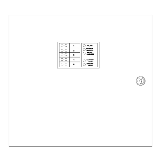
5.5 BATTERY FAULT LED Battery removal, low voltage and open battery leads will turn on the yellow battery fault LED and the common trouble LED. 5.6 GROUND FAULT LED Any ground fault of 10K ohms or less will turn on the yellow ground fault LED steadily, flashing the common trouble LED and sounding the common trouble buzzer intermittently. -
Page 8: System Checkout
7. SYSTEM CHECKOUT BEFORE TURNING POWER ON: 1. Check all external wiring for opens, shorts or grounds. 2. Check that transformer cables are securely connected. 3. Check the A.C. power wiring for proper connection. DO NOT connect batteries in order to prevent sparking. -
Page 9: Backbox & Flush Trim Mounting Details
FIGURE 1: BACKBOX & FLUSH TRIM MOUNTING DETAILS... -
Page 10: Circuit Board Layout
FIGURE 2: CIRCUIT BOARD LAYOUT... -
Page 11: Detection And Signal Wiring Instruction
FIGURE 3: DETECTION AND SIGNAL WIRING INSTRUCTION... -
Page 12: Wiring Table For Detection Zones
FIGURE 4: WIRING TABLE FOR DETECTION ZONE... -
Page 13: Wiring Table For Bells And Horns
FIGURE 5: WIRING TABLE FOR BELLS AND HORNS... - Page 14 FIGURE 6: ALARM , TROUBLE RELAY CONTACTS AND REMOTE ANNUNCIATION WIRING INSTRUCTION -10-...
-
Page 15: Smoke Detector
2. Whether mixing different models of compatible smoke detectors, or using the same model on the same Circuit, total standby current of all detectors must not exceed 3 mA. SMOKE DETECTOR MAKE MODEL / BASE MAKE MODEL / BASE MAKE MODEL / BASE MIRCOM CERBERUS PYROTRONICS FENWAL MIR-525 D1-2 PSD-7131 / 70-201000-001... - Page 16 A - A 0.12 mA 4451HT / B401B A - A 0.12 mA 4451HT / B406B A - A 0.12 mA MIRCOM 4451HT / B401 A - A 0.12 mA MIR-525U FDT-1 0.10 mA 5451 / B401B A - A 0.12 mA...
- Page 17 UNDERWRITER’S LABS INC. (ULI) UNITED STATES SIGNALING DEVICE CONTROL PANEL COMPATIBILITY System Sensor - SpecrAlert P2415 P2415W P241575 P241575W P2475 P2475W P24110 P24110W S2415 S2415W S241575 S241575W S2475 S2475W S24110 S24110W H12/24 H12/24W MDLW Wheelock AS-2415W-24-FR AS-241575W-FR AS-2430W-FR AS-2475W-FR AS-24110W-FR AS-2415C-FW AS-2430C-FW AS-2475C-FW...
-
Page 18: Appendix "B" Battery Calculations
ALARM FA-101U Fire Alarm , 1 Det, 1 Sig 0.066 0.125 FA-102U Fire Alarm, 2 Det, 1 Sig 0.076 0.135 FA-1025U Fire Alarm, 5 Det, 2 Sig 0.114 0.200 RTI-1 Remote Trouble Indicator 0.035 0.035 2-Wire Smoke Detectors ' 0.0001 * 0.090... - Page 19 MIRCOM Technologies Ltd., manufactured equipment is guaranteed to be free of defects in material and workmanship for a period of one (1) year from the date of original shipment. MIRCOM will repair or replace, at its option, any equipment which it determines to contain defective material or workmanship.
Need help?
Do you have a question about the FA-1025U and is the answer not in the manual?
Questions and answers