Table of Contents
Advertisement
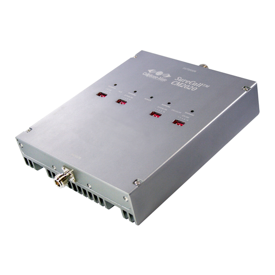
CM2020 Dual Band Amplifier
Upl i nk Freq. Ra nge (MHz)
824-849/1850-1910
Down Freq. Ra nge (MHz)
869-894/1930-1990
Supported Sta nda rds
CDMA, WCDMA,GSM,RDGE,TDMA AMPS.etc
Ga i n Adjus tment Ra nge
31dB
68/ 75/ 80dB
Si gna l Ga i n (depends on model)
Input/Output Impeda nce
50Ω
Noi s e Figure
5dB
VSWR
≤2.0
AC Power Tra ns former
110VAC, 60Hz IN / 5-20VDC OUT
Ca bl e
CM400 or LMR400
Power Cons umption
<20W
Di mens i ons
7.50" x 9.00" x 2"
Wei ght
6.5 l b
This manual applies to all CM2020 models.
Cellphone-Mate, Inc.
CM2020 (05/12) v1.1
Technical Support:
888.365.MATE (6283) phone
510.996.7250 fax
www.surecall.com
ENTERPRISE RECEPTION SOLUTION
Enterprise Cellular Amplifier
CM2020
User Manual
PARTS NO: CM2020-68/CM2020-75/CM2020-80
Advertisement
Table of Contents

Subscribe to Our Youtube Channel
Related Manuals for SureCall CM2020


Summary of Contents for SureCall CM2020
- Page 1 110VAC, 60Hz IN / 5-20VDC OUT www.surecall.com Ca bl e CM400 or LMR400 Power Cons umption <20W Di mens i ons 7.50” x 9.00” x 2” Wei ght 6.5 l b This manual applies to all CM2020 models. PARTS NO: CM2020-68/CM2020-75/CM2020-80...
-
Page 2: Table Of Contents
Table of Contents CHAPTER 1: Introduction - - - - - - - - - - - - - - - 1 4.2 - Soft Installation - - - - - - - - - - - - - - - - - 17 4.3 - Exterior Antenna - - - - - - - - - - - - - - - - 17 1.1 - Package Contents - - - - - - - - - - - - - - - - 1 4.4 - Internal Antennas - - - - - - - - - - - - - - - 18... - Page 3 UAL IN A READILY ACCESSIBLE LOCATION IN CASE ANY QUESTIONS ARISE ABOUT THIS PRODUCT. Copyright © 2011 by Cellphone-Mate, Inc. All rights reserved. SureCall is a registered trademark and Cellphone-Mate is a trademark of Cellphone-Mate, Inc. All other trademarks or registered trademarks are the property of their respective owners.
-
Page 4: Chapter 1: Introduction
CHAPTER 1: Introduction This chapter introduces the CM2020 Amplifier and this manual. Read this entire manual before proceeding with the installation. This manual applies to all CM2020 models. 1.1 - Package Contents Your amplifier box contains the following items: • CM2020 amplifier. -
Page 5: Features & Benefits
1.2 - Features & Benefits The CM2020 amplifier offers the following fea- CM2020 amplifier tures and benefits: requires following components for • Powerful in-building amplifier with 31dB of adjustable gain level. • External antenna (such • Extends cellular signals in areas with poor cov-... -
Page 6: How It Works
1.4 - How It Works • Sufficient CM400 ultra low loss interior/exte- rior cable (for amplifi- The CM2020 amplifier boosts cellular signals from ers above 55dB). the nearest tower to phones in a building and from those phones back to the tower to compen- •... - Page 7 CM2020 Amplifier - Installation Manual • Introduction: This chapter introduces the Procedures that must be followed in a specific CM2020 amplifier and this manual. order appear in numbered steps: • Safety: This chapter contains important safety 1. Perform this step first.
-
Page 8: Chapter 2: Safety
CHAPTER 2: Safety This chapter contains important • The installation process may require working in high locations such as roofs and/or ladders. safety information designed to pre- Follow applicable safety regulations and best vent personal injury, equipment mal- practices to avoid falling. Take care not to drop objects off any high area. - Page 9 CM2020 Amplifier - Installation Manual • Some components may be heavy and/or • Always power off the amplifier before working bulky. Always use proper lifting and carrying on the roof of the building or anywhere in techniques when handling components, espe- close proximity to the external antenna.
-
Page 10: Chapter 3: Planning
CHAPTER 3: Planning This chapter describes how to plan or a directional Yagi antenna pointed directly at the cellular tower (line of sight). You must your amplifier installation, including also consider attaching a grounded lightning how to determine the best locations protector between the exterior antenna and the amplifier. -
Page 11: Exterior Antenna
CM2020 Amplifier - Installation Manual 4. Decide where to route the cables between the omnidirectional antenna receives and transmits exterior antenna and the amplifier and signals over a horizontal 360-degree circle while between the amplifier and interior antennas. the Yagi antenna receives and transmits signals over a focused area and must be aimed directly 5. -
Page 12: Interior Antennas
CHAPTER 3: Planning • Not collocated with other antennas or used in flat panel antennas such as the CM248W provide conjunction with other antennas. a focused zone of coverage suitable for long narrow areas. The following example uses two dome •... -
Page 13: Antenna Separation
CM2020 Amplifier - Installation Manual 3.4 - Antenna Separation Keep in mind that floor structures in multistory buildings can cause significant signal loss, which means that you may need to install interior anten- Proper antenna separation is essential in order to nas on more than one floor. - Page 14 CHAPTER 3: Planning Distance from Point b to directly under- neath the exterior antenna. This is Point Note: Vertical separation is more impor- (c). This is distance bc. tant than horizontal separation. If you are unable to obtain the required sepa- Distance from Point c to the exterior ration horizontally, try raising the exte- antenna (Point d).
- Page 15 CM2020 Amplifier - Installation Manual 7. The straight-line distance ad is the square root Separate interior antennas based on the calcula- ( ) of the result obtained in Step 6. tions shown in Section 3.5. You may mix and...
-
Page 16: Calculating Signal Strength
CHAPTER 3: Planning • Inside antenna gain (IAG): This is the signal boost provided by an interior antenna and is You can calculate the number of antennas you will always a number with Cellphone- need using the following parameters (in dB): Mate antennas. -
Page 17: Amplifier Location
CM2020 Amplifier - Installation Manual • Splitter loss (SL): This is the signal loss caused 2. Find the signal strength S for the antenna by a splitter (used if you are installing multiple along the bottom of the graph on the follow- antennas). -
Page 18: Accessories
CHAPTER 3: Planning 3.7 - Accessories to help ensure personal safety during The final step in the planning process is to make sure you have all of the necessary accessories to complete the You will need all of the items listed in Chapter 1 of this manual plus some Note: You may need to obtain a permit or all of the following: from your local building department to... -
Page 19: Need Help
3.8 - Need Help? If you need help planning your please contact a qualified installer, the reseller from whom you purchased the amplifier, or Cellphone- Mate, Inc. Copyright 2011 Cellphone-Mate, Inc. All rights reserved. -
Page 20: Chapter 4: Installation
CHAPTER 4: Installation This chapter describes how to install 4.2 - Soft Installation the amplifier and antennas for best Perform a “soft” installation of all components to results. test signal coverage and oscillation before making the installation permanent. Avoid making holes or other permanent fixtures during this initial phase. -
Page 21: Internal Antennas
• An antenna (CM100-L, CAUTION: AVOID AIMING A YAGI ANTENNA TOWARD ANY INTERIOR (Please not, the CM100-L and CM100-S antennas are dual band ANTENNA . and the CM288W and 230W antennas are wide-band.) • A Yagi antenna (such as the CM230W) must be 1. -
Page 22: Mounting The Amplifier
CHAPTER 4: Installation to follow the instructions included with the 2. Connect a length of CM400 or CM240 cable to antenna(s) for a safe installation. Remember: the antenna and tighten until hand-tight. • Dome antennas (CM222W, CM223, etc.) should 3. If you are installing multiple antennas, run the be mounted in the ceiling as close to the cen- cable to the splitter location and connect the ter of the desired coverage area as possible... - Page 23 CM2020 Amplifier - Installation Manual 2. Attach the included mounting kit to the ampli- 6. Verify that all cable connections are snug and fier using the screws provided. Tighten the that the exterior and interior antennas are screws by hand with a screwdriver until snug connected to the proper jacks.
-
Page 24: Chapter 5: Configuration & Testing
• Cellular Downlink Warning light/DIP switches 5.1 - DIP Switches and Lights (4): These DIP switches control the cellular amplification within the building. The CM2020 amplifier has the following indicators • Cellular Uplink Warning light/DIP switches and controls: (5): These switches control the cellular com- •... - Page 25 CM2020 Amplifier - Installation Manual When the amplifier is powered on: From left to right, the DIP switches in each bank provide 1, 2, 4, 8, and 16 dB of attenuation • The green Power light (3) should illuminate. (reduced amplification). These switches are cumu- •...
-
Page 26: Initial Configuration
CHAPTER 5: Configuration & Testing • Turning ON all switches in a bank = 1. Make sure that exterior and interior antenna 1+2+4+8+16dB attenuation = 31dB attenua- cables are snugly connected to the proper tion. For example, in a 68dB amplifier, that ports on the amplifier. -
Page 27: Testing
CM2020 Amplifier - Installation Manual 5. Verify that the green Power light is illumi- 7. Once the amplifier is powered on and no red nated. Warning lights are illuminated, you may pro- ceed to adjust the amplifier. 6. If any red Warning light(s) illuminate, immedi- ately power off the amplifier by either unplug- 5.4 - Testing... - Page 28 CHAPTER 5: Configuration & Testing many areas of the building as possible. A suc- (if equipped). If oscillation is or becomes cessful installation means that you can make severe, the amplifier will power down and will calls without dropping and/or have a reliable then wake every 30 seconds for the next 15 data connection.
-
Page 29: Automatic Shutdown
5.6 - Automatic Shutdown eral, the cellular side will oscillate more easily than the PCS side. If equipped, the CM2020 amplifier includes an 4. The amplifier will wake back up. When this automatic shutdown feature that works in the fol- occurs, the power light will be green. -
Page 30: Chapter 6: Warranty
CHAPTER 6: Warranty This chapter contains the warranty solely the fault of CELLPHONE-MATE Inc. Incorrect installation or misuse will void this information for your CELLPHONE- warranty. Upon the return of a defective prod- MATE product and also contains uct, CELLPHONE-MATE will issue the customer a working replacement. -
Page 31: Warranty Information
CM2020 Amplifier - Installation Manual 6.2 - Warranty Information ucts without incurring any obligation to make the same changes on previously delivered 1. CELLPHONE-MATE, Inc. warrants to the Buyer products. that each of its products will be free from 2. As a condition of the warranties provided for... - Page 32 CHAPTER 6: Warranty ing to the Buyer’s order if they satisfactorily IMPLIED, IN LAW OR IN FACT, ORAL OR IN fulfill the performance requirements that WRITING. CELLPHONE-MATE, INC.’S AGGRE- were published in the product specification lit- GATE LIABILITY IN DAMAGES OR OTHERWISE erature, or in accordance with samples pro- SHALL NOT EXCEED THE PAYMENT, IF ANY, vided by CELLPHONE-MATE, Inc.
-
Page 33: Contact Information
CM2020 Amplifier - Installation Manual 6.3 - Contact Information award rendered may be entered in any court having jurisdiction thereof. You may consult a Cellphone-Mate, Inc. customer 7. If one or more provisions provided herein are service agent directly by contacting us as follows:... -
Page 34: Chapter 7: Regulatory Information
CHAPTER 7: Regulatory Information This chapter contains the regulatory provide reasonable protection against harmful interference in a residential installation. This information for the FCC (USA) and equipment generates, uses, and can radiate radio Industry Canada (Canada). frequency energy and, if not installed and used in accordance with the instructions, may cause harmful interference to radio communications. -
Page 35: Industry Canada
CM2020 Amplifier - Installation Manual 7.2 - Industry Canada • Connect the equipment to an outlet on a cir- cuit different from that to which the receiver is connected. IC ID: 7784A-D85UNDER • Consult the dealer or an experienced radio/TV This device meets all requirements of the Cana- technician for help. - Page 36 CHAPTER 7: Regulatory Information ated and can cause interference to adjacent band centes à la bande utilisateurs. Ce pouvoir est de la users. This power reduction is to be by means of réduction par le biais de la sortie d’alimentation input power or gain reduction and not by an ou la réduction de gain et non par un atténuateur attenuating at the output of the device.
- Page 37 CM2020 Amplifier - Installation Manual This page intentionally left blank. Copyright 2011 Cellphone-Mate, Inc. All rights reserved.
Need help?
Do you have a question about the CM2020 and is the answer not in the manual?
Questions and answers