Table of Contents
Advertisement
Advertisement
Table of Contents

Related Manuals for Glidecam Industries Glidecam HD-1000


Summary of Contents for Glidecam Industries Glidecam HD-1000
- Page 1 1 0 0 0 / 2 0 0 0 / 4 0 0 0 MANUAL Set-up and Operations Guide Glidecam Industries, Inc. 23 Joseph St, Kingston, MA 02364 Customer Service Line 1-781-585-7900 Manufactured in the U.S.A. COPYRIGHT 2008-2009 GLIDECAM INDUSTRIES,INC. ALL RIGHTS RESERVED...
-
Page 2: Table Of Contents
table of contents SECTION # PAGE # 1. Introduction 2. Glidecam HD-2000 Parts and Components 3. Assembling your Glidecam HD-2000 4. Attaching your camera to your Glidecam 5. Balancing your Glidecam HD-2000 6. Handling your Glidecam HD-2000 7. Operating your Glidecam HD-2000 8. -
Page 3: Please Note
PLEASE NOTE Since the Glidecam HD-2000 is essentially the same as the HD-1000 and the HD-4000, this manual only shows photographs of the Glidecam HD-2000 being setup and used. The Glidecam HD-1000 and the HD-4000 are just smaller and larger versions of the HD- 2000. -
Page 4: Introduction
#1 Introduction Congratulations on your purchase of a Glidecam HD-1000 and/or Glidecam HD-2000/Glidecam HD- 4000. The amazingly advanced and totally re-engineered HD-Series from Glidecam Industries represents the top of the line in hand-held Camera Stabilization. The lightweight and state-of-the-art Glidecam HD-1000, HD-2000, and HD-4000 hand-held Camera Stabilizers will transform your hard to watch, shaky camera footage into hypnotically smooth, professional footage. -
Page 5: Glidecam Hd-2000 Parts And Components
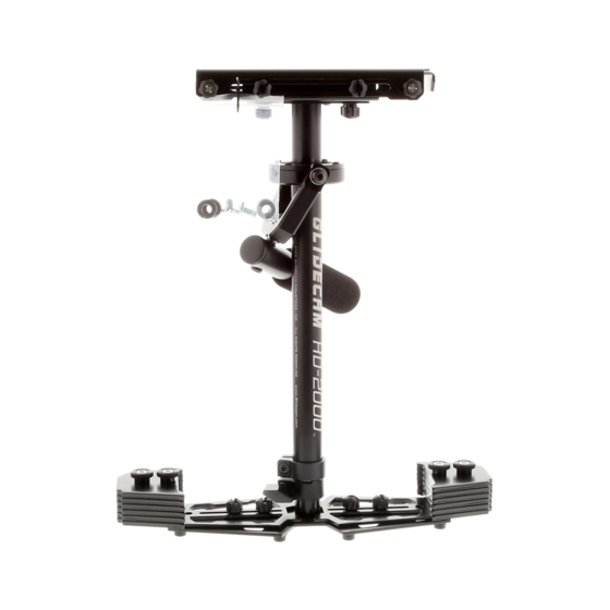
If you have need of any technical assistance, you can call our Technical Support Line at 1-781-585-7900, Monday through Friday between the hours of 9:00 am and 5:00 pm, Eastern Time. We’re sure that once you have your Glidecam HD-1000, HD-2000, or HD-4000 up and running, you will find years of enjoyment with it. - Page 6 This is the Glidecam HD-2000 CENTRAL POST with attached gimbal assembly. ***The HD-1000 has a smaller CENTRAL POST and the HD-4000 has a longer CENTRAL POST. Warning – Do not adjust or tighten the factory settings on the gimbal, handle, and yoke.
- Page 7 ***The QUICK RELEASE PLATES for the HD-1000 and the HD-4000 are different. This is the CAMERA-MOUNTING PLATFORM with front to back and side to side movement adjustment knobs.
- Page 8 These are the 10 HD2000 and HD4000 COUNTER WEIGHT PLATES (shown in bag). The HD1000 has 8 COUNTER WEIGHT PLATES. This is the HARDWARE set for the Glidecam HD-2000. ***The Glidecam HD-1000 and HD-4000 have slightly different HARDWARE.
- Page 9 Camera Mounting Screws Counter Weight Plates ¼”Washers Black Bolts for Counter Plates Rubber Washers Black Thumb Nuts...
-
Page 10: Assembling Your Glidecam Hd-2000
#3 Assembling your Glidecam HD-2000 First, get the BASE PLATFORM and the TELESCOPING POST. photo BASE PLATFORM and photo #12 for the TELESCOPING POST. Note the threaded insert located in the bottom of the TELESCOPING POST. - Page 11 Connect the TELESCOPING POST to the BASE PLATFORM by tightly screwing the TELESCOPING POST onto the treaded stud sticking up from the center of the BASE PLATFORM. At this point, your Glidecam HD-2000 should look like photo #14 which is showing TELESCOPING POST...
- Page 12 Now find a pair of bolts and attach RUBBER WASHERS as shown in the photo to the left. Repeat this step. Now, insert the selected bolts with RUBBER WASHERS attached through the slots in the BASE PLATFORM as shown in this picture and repeat this procedure for the slots on the other side of the BASE PLATFORM.
- Page 13 Take COUNTER WEIGHT PLATES and slide them down the bolts on the BASE PLATFORM (the holes in the weights match the placement of the bolts). NOTE: Heavy Cameras require more COUNTER WEIGHTS than light Cameras Secure the COUNTER WEIGHT PLATES with the BLACK THUMB NUTS as shown in this photo and repeat this procedure for the COUNTER WEIGHT...
- Page 14 Now, insert the TELESCOPING POST with the attached BASED PLATFORM up into the CENTRAL POST (the Central Post can be seen in photo #21). TELESCOPING CLAMP’S “Adjustment Knob” should be aligned so that it looks like it does in photo #22. To align the TELESCOPING CLAMP’S “Adjustment Knob”...
- Page 15 Securely tighten the “Adjustment Knob” on the TELESCOPING CLAMP by rotating the Knob clockwise as shown in this photo. The “Adjustment Knob” should only be tightened by hand. WARNING: DO NOT OVERTIGHTEN THIS KNOB. At this point, this is what your HD-2000 should look like, which is with the CENTRAL POST and TELESCOPING POST...
- Page 16 This is a photo of the THREADED INSERT in the top of the CENTRAL POST. Rotate screw CAMERA MOUNTING PLATFORM into THREADED INSERT in the top of the CENTRAL POST. In the next procedure you are going to align the CAMERA MOUNTING PLATE so that its front edge is parallel to the front edge of the BASE PLATFORM.
- Page 17 Knob later when you use it. IMPORTANT NOTE: When using cameras that are less than one pound on the HD-1000 you will need to increase the camera weight by adding counter balance weight plates under the camera.
-
Page 18: Attaching Your Camera To Your Glidecam
#4 Attaching your camera to the Glidecam HD-2000 ***PLEASE NOTE*** These photographs show the GLIDECAM 2000 PRO for illustrative purposes. Now it is time to attach your Camera to the Glidecam HD-2000’s Quick Release Plate. To remove the quick release plate from the head assembly turn the knobs counterclockwise and then pull on the knobs to release. - Page 19 WASHERS at all if you trouble with the mounting procedure. ***You can use the same MOUNTING SCREWS and WASHERS for the HD-1000 and HD-4000. With your Camera base side up in your lap and with the QUICK RELEASE PLATE in...
- Page 20 If all is correct, your Camera and QUICK RELEASE PLATE should now be securely attached to each other as shown in Photo #35 NOTE: If you can easily rotate the QUICK RELEASE PLATE on the base of your Camera, even though you have adequately tightened the CAMERA MOUNTING SCREW, and you do not feel comfortable tightening the CAMERA MOUNTING SCREW any more, then you should...
-
Page 21: Balancing Your Glidecam Hd-2000
#5 Balancing your Glidecam HD-2000 Before you begin the balancing process check for the following: 1) Camera is securely attached to the QUICK RELEASE PLATE and the four knobs are pushed in and tightened. 2) Lens cap has been removed and secure. 3) Camera Battery and Video Tape are installed 4) Flip out LCD in its operating position (if... - Page 22 When testing for correct horizontal balance you need to make sure that you pick up your HD-2000 from a flat and level surface (a table for example) and that you let the HD-2000 hang freely as you hold it as shown in Photo # 38.
- Page 23 If the HD-2000 leans to the right, then you will have to loosen the THUMB SCREWS on the bottom of the CAMERA MOUNTING PLATFORM and then turn side side adjustment knob counterclockwise. If the HD-2000 leans to the left from the operator’s point of view as in Photo #41 then move it to the right by turning the side to side adjustment knob clockwise.
- Page 24 NOTE: LATER AFTER YOU ADJUST THE VERTICAL BALANCE OF THE HD-2000 YOU WILL HAVE TO GO BACK AND READJUST THE HORIZONTAL BALANCE AGAIN IN ORDER TO OBTAIN A TRUE FINE BALANCE WHOLE SYSTEM. BALANCING THE VERTICAL AXIS Now that your HD-2000 is horizontally balanced, it’s vertical axis can now be tested and properly balanced.
- Page 25 To test the balance of the vertical axis, perform what is called the SLED ARC TEST. To perform the “Sled Arc Test,” simply hold the HD-2000 by its handle and then grab hold of the back end of the HD-2000’s BASE PLATFORM, then pull the BASE up and back until the HD-2000’s CENTRAL POST is horizontal and motionless (see Photo #42).
-
Page 26: Handling Your Glidecam Hd-2000
#6 Handling Your Glidecam HD-2000 Before you operate and film things with your HD- 2000, you will need to know how to handle it. When handling your HD-2000 you will use on hand to hold onto the handle and the other hand to gently guide the Camera in the direction you wish to shoot. -
Page 27: Operating Your Glidecam Hd-2000
#7 Operating your Glidecam HD-2000 The Glidecam HD-2000 is designed to work correctly only when operated with two hands (see Photos 46 and 48). If you try to operate the unit with just your “Holding Hand,” the Camera will most likely drift away from its original position. - Page 28 Photos #51 through #53 show the Glidecam HD-2000 being held and used in different ways. Operating your Glidecam HD-2000 extended periods of time can easily tire your “Holding Hand.” If fatigue sets in while shooting you can try operating the Glidecam HD-2000 with your other hand.
-
Page 29: Shooting Tips
#8 Shooting Tips Use of a Wide Angle Lens Converter If you have a common consumer Camcorder you will probably discover that the widest focal length setting on its lens is not very wide. You might find that this wide setting is not adequate enough to give you the look produced by professional Hollywood dollies, cranes, and stabilizers. -
Page 30: Improper Techniques
#9 Improper Techniques When shooting with the Glidecam HD- 2000, do not grab the CENTRAL POST as in Photo #56. This defeats the purpose and isolation that the three axis gimbal provides. Instead, handle your Glidecam HD-2000 as shown in Photo #46 and #48. Do not allow the Handle of the Glidecam HD-2000 to come in contact with CAMERA MOUNTING PLATFORM as... -
Page 31: Other Camera Attachment Methods
#10 OTHER CAMERA ATTACHMENT METHODS Creating a gasket - If when attaching your camera to the QUICK RELEASE PLATE you find that the bottom of your camera isn’t flat enough to allow for a good solid attachment, try making and adding a paper/cloth or rubber gasket to the QUICK RELEASE PLATE. -
Page 32: Maintenance
#12 MAINTENANCE Bearing Maintenance: The main bearing on your Glidecam HD-2000 is attached to the Central Support Post about two inches down from the top. It is metal and is partially enclosed by the Bearing Assembly. If after some period of time your bearing doesn’t turn smoothly, you can oil it lightly with light lubricating oil. -
Page 33: Warranty
PARTICULAR PURPOSE, ARE LIMITED TO THE NINETY (90) DAY WARRANTY PERIOD. To obtain service during (or after) the warranty period: Contact Glidecam Industries’ Customer Service Department by calling 1-781-585-7900 or write to us at: 23 Joseph St., Kingston, MA 02364, and explain the problem. -
Page 34: Online Information
For more information product GLIDECAM performance and training please visit the video page and GLIDECAM workshop page. GLIDECAM www.glidecam.com/videos.php www.glidecam.com/workshops.php...
Need help?
Do you have a question about the Glidecam HD-1000 and is the answer not in the manual?
Questions and answers