Table of Contents
Advertisement
Quick Links
Advertisement
Table of Contents

Related Manuals for Glidecam Industries X-10


Summary of Contents for Glidecam Industries X-10
- Page 1 X-10 Quick Setup Guide GLIDECAM INDUSTRIES, INC. 23 Joseph Street Kingston, MA 02364 Customer Service Line: 781-585-7900 Manufactured in the U.S.A . © COPYRIGHT 2007-2008 GLIDECAM INDUSTRIES, INC., ALL RIGHTS RESERVED Glidecam is registered at the PATENT and TRADEMARK office.
-
Page 3: Table Of Contents
TABLE OF CONTENTS 1. INTRODUCTION 2. QUICK SETUP 3. ADJUSTING THE LOAD SETTINGS OF YOUR SUPPORT ARM 4. REMOVING THE SPRINGS FROM YOUR SUPPORT ARM 5. INSTALLING THE SPRINGS INTO YOUR SUPPORT ARM 6. SPECIFICATIONS 7. WARNINGS 8. MAINTENANCE 9. WARRANTY... -
Page 5: Introduction
INTRODUCTION Congratulations on your purchase of a GLIDECAM X-10. In order to use the GLIDECAM X-10 system, it is best to have a basic understanding of how the system works in advance. So please make sure you read this section before trying to setup and operate the GLIDECAM X -10. - Page 6 While the GLIDECAM X-10 is in essence a very simple device, its simplicity doesn’t lend ease in answering that often asked question, “how does it work?” To answer this question would require delving into Newtonian Physics and Classical Mechanics. We would have to explain center of gravity displacement, inertia, reduced friction and angular motion reduction etc.
-
Page 7: Quick Setup
CHAPTER TWO QUICK SETUP Since you will be using your GLIDECAM X-10 with either a GLIDECAM 2000 PRO or a GLIDECAM 4000 PRO (hereafter referred to as the SLED), you should make sure that your SLED is already setup and properly balanced. Please see the GLIDECAM 2000 PRO or 4000 PRO Manual for details regarding proper SLED setup and balancing procedures. - Page 8 Figure 3 When you park your SLED onto the DOCKING BRACKET, make sure that the SLED’S HANDLE is facing directly outwards as in figure 3. By parking your SLED this way on the DOCKING BRACKET, it will be easily accessible to you when it comes time to put the SLED onto the end of the SUPPORT ARM.
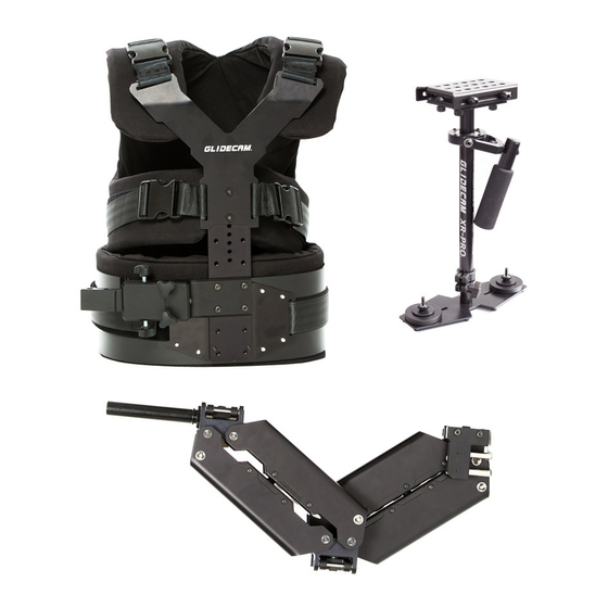
- Page 9 THE GLIDECAM X-10 SUPPORT ARM The GLIDECAM X-10’s Dyna-Elastic™ dual-articulating SUPPORT ARM incorporates 38 precision radial bearings within its machined T6 aluminum structure. The placement and implementation of these double-shielded bearings produce minimal friction and allow the Dyna-Elastic™ SUPPORT ARM to pivot and boom very smoothly, and with virtually no noise.
- Page 10 Figure 4 The GLIDECAM X-10 SUPPORT ARM (figure 4) comes pre -configured with four EXTENSION SPRINGS, which are already installed. These SPRINGS are also preset to their weakest LOAD SETTING. Later, in the CONFIGURATION SECTION, we will discuss how to make adjustments to the arm in detail. For now, leave the SPRINGS in the SUPPORT ARM at their factory setting.
- Page 11 7. Do not OVERTIGHTEN this PLASTIC TIGHTENING SCREW, for this could damage the THREADS. The reason that the TIGHTENING SCREW is made of plastic is so that it will not scratch the ARM POST. THE GLIDECAM X-10 SUPPORT VEST...
- Page 12 The GLIDECAM X-10 SUPPORT VEST is lightweight, comfortable and can be adjusted to fit a wide range of operators. High endurance, dual density, EVA foam padding and integral T6 aluminum alloy create a vest that can hold and evenly distribute the weight of the system across the operator's shoulders, back, and hips.
- Page 13 Figure 9 Connect the GLIDECAM X-10 SUPPORT ARM to the GLIDECAM SUPPORT VEST. First, note the location of the two RECEIVING HOLES in the ARM CONNECTOR BAR shown by the solid arrow in figure 9.
- Page 14 Figure 10 If everything has been done properly so far, you should now have the SUPPORT ARM attached to the VEST, as in figure 10 (without the camera). Figure 11 Figure 12...
- Page 15 You can now attach the SUPPORT ARM to the SLED by carefully aligning and guiding the ARM POST all the way into the bottom of the SLED HANDLE as in figures 11 and 12. After you have done this, hold onto the SLED HANDLE firmly so that as you carefully lift the SLED straight up and out of the DOCKING BRACKET, you can make sure that the weight of the SLED is in the control of your ARM and not the SPRING-LOADED SUPPORT ARM.
- Page 16 Figure 14* The GLIDECAM X-10 is designed to work best when the system is operated with the SLED positioned directly in front of you, as in figures 14 and 15. This position allows you a clear view of either the LCD MONITOR on your camcorder or the LCD MONITOR on the BASE PLATFORM of your SLED.
-
Page 17: Adjusting The Load Settings Of Your Support Arm
SPRING from the ARM. Both of these changes can be made using the supplied ALLEN WRENCHES (not shown). When you receive your GLIDECAM X-10, it comes pre-configured with four SPRINGS already installed and set to their weakest SPRING TENSION setting. - Page 18 Figure 17 Figure 18...
- Page 19 18-pound SLED is used with four SPRINGS installed in the arm. We have provided six STEEL WEIGHT PLATES (figure 19) with the GLIDECAM X-10 so that you may use them to increase the total weight of your SLED.
- Page 20 Figure 19 The heavy, stainless steel ARM POST weighs approximately 1.25 pounds and can be used to quickly increase the total load at the end of the ARM. Increasing the load at the end of the SUPPORT ARM is, in effect, equivalent to increasing the weight of the SLED.
-
Page 21: Removing The Springs From Your Support Arm
CHAPTER FOUR REMOVING THE SPRINGS FROM YOUR SUPPORT ARM Figure 21 In general, when using a GLIDECAM 2000 PRO, you will achieve superior stabilization with only two SPRINGS installed in the SUPPORT ARM. When using a GLIDECAM 4000 PRO, you will achieve superior stabilization with four SPRINGS installed in the SUPPORT ARM. - Page 22 Figure 23 In order to remove or install either of the SPRINGS in the SUPPORT ARM, you must first make sure that the SLED is not on the end of the ARM and that the ARM is not attached to the VEST. You must also make sure that the ARM is not under load and that it is angled upwards.
- Page 23 Figure 24 Figure 25 With the ARM angled downwards, you can now easily remove the RETAINING BOLTS as shown in figures 24 and 25.
- Page 24 Figure 26 Now that the ADJUSTER BOLT and RETAINING BOLTS are disconnected from each end of the SPRING, you will be able to slide the SPRING out of the SUPPORT ARM as shown in figure 26.
- Page 25 CHAPTER FIVE INSTALLING THE SPRINGS INTO YOUR SUPPORT ARM Figure 27 Figure 28 When installing the SPRINGS into the SUPPORT ARM, you need to make sure you are holding the back end of the SPRING (shown in figure 28) and inserting the front end of the SPRING (shown in figure 27) into the SUPPORT ARM, as shown in figure 29.
- Page 26 Make sure the SUPPORT ARM is angled downwards so you can easily install the SPRINGS. Figure 30 Insert the SPRING into the SUPPORT ARM. Next, thread the RETAINING BOLTS into the end of the SPRING and use the ALLEN WRENCHES to firmly tighten the RETAINING BOLTS into the back of the SPRING as shown in figure 30.
- Page 27 Figure 32 Now that the SPRING is connected to the RETAINING BOLTS, angle the SUPPORT ARM upwards, taking care that the HEADS of the RETAINING BOLTS do not hit any part of the ARM as in figure 32. Figure 33...
- Page 28 With the SPRING inside the SUPPORT ARM and the ARM angled upwards, manually connect the ADJUSTER BOLT so that it threads into the center of the SPRING as shown in figure 33. Using an ALLEN WRENCH, rotate the ADJUSTER BOLT clockwise until the SPRING reaches at least the position marked “0”...
-
Page 29: Installing The Springs Into Your Support Arm
Individual Weight Plates: each 12.9oz (366 grams) All measurements and weights are approximate. The GLIDECAM X-10 System includes: GLIDECAM X-10 SUPPORT ARM, SUPPORT VEST, DOCKING BRACKET, (1) Stainless Steel ARM POST, (1) Aluminum ARM POST, (6) Steel WEIGHT PLATES, Hardware and Operations Manual. -
Page 31: Warnings
You should also make sure that you are very careful when u sing the GLIDECAM X-10 at night or in low light conditions. Do not make the mistake of focusing so much on what you are shooting that you trip over something, or wander into something dangerous like a body of water or automobile traffic. -
Page 33: Maintenance
WAIST SUPPORT section of the VEST too tightly, as this could break the plastic. Also, when shipping, make sure that all of the parts of the GLIDECAM X-10 are packed in such a way that they cannot bang into, or rub directly against one another. -
Page 35: Warranty
For one year from the date of shipment, we will repair or replace your Glidecam X-10, free of charge, in the event of a defect in materials or workmanship (the shipment date appears on your purchase receipt) that occurs during normal use in accordance with the Glidecam X-10’s instruction manual.
Need help?
Do you have a question about the X-10 and is the answer not in the manual?
Questions and answers