Table of Contents
Advertisement
Quick Links
Columbia/Shenandoah
®™
Waste Oil-Fired Boiler
Owner's Manual
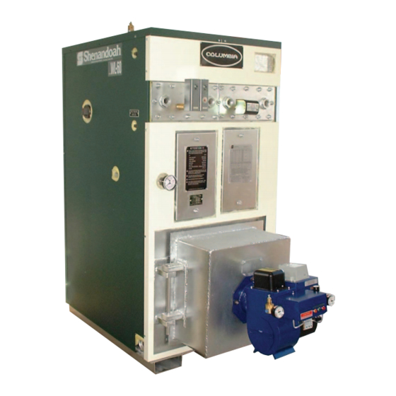
WL-60 / L-24 Boiler
All Installations Must Be In Accordance With State and Local Codes and it is
the responsibility of the installer to assure all codes are met
For service, call your dealer or installer at:
or Columbia Boiler at (610) 323-2700 to find the distributor for your area
Date Installed: ____________________________
WARRANTY NOTICE
Use of Columbia Boiler Company equipment on equipment not manufactured or designed for use by
Columbia Boiler, VOIDS the warranty - property or personal damage could occur.
Sizing of the boiler is the responsibility of the purchaser.
A complete heat loss calculation for the structure or process is necessary to select the proper unit size.
Columbia Boiler Company
P O Box 1070
Pottstown, PA 19464 USA
Advertisement
Table of Contents

Related Manuals for Columbia WL-60


Summary of Contents for Columbia WL-60
- Page 1 Date Installed: ____________________________ WARRANTY NOTICE Use of Columbia Boiler Company equipment on equipment not manufactured or designed for use by Columbia Boiler, VOIDS the warranty - property or personal damage could occur. Sizing of the boiler is the responsibility of the purchaser.
-
Page 3: Table Of Contents
TABLE OF CONTENTS SUBJECT PAGE PACKING LIST SPECIFICATIONS WL 60 / L 24 BOILER CONTROLS BOILER FLAME & BRICK INSTALLATION INSTRUCTIONS 10-11 CONTROL LOCATIONS & PORTS WL 60 NOTES CONTROL LOCATIONS & PORTS L 24 18-19 COIL INSTALLATION L24/WL60 BASIC BOILER & RADIANT HEAT INFORMATION CABINET / JACKET ASSEMBLY WATER TREATMENT 23-25... -
Page 4: Packing List
PACKING LIST 1 Boiler (coils installed if ordered) 1 Carton of cabinet panels 1 Temp/Pressure Gage 1 ASME Relief Valve (15 psi steam or 30 psi water) 1 Operating Aquastat w/ Thermowell or Steam Control 1 High Limit Aquastat w/ Thermowell or High Limit Steam Control 1 Low Water Cutoff w/ remote sensor (manual reset unless specified) 1 Water Level Gauge (glass) When boiler ordered as steam 1 Boiler Manual... - Page 5 COLUMBIA WL-60 WASTE OIL-FIRED BOILERS Product Specifications 1. Boiler Construction: 1. Boiler shall meet EPA exemption guidelines for safe disposal (40 CFR 266) of used oil. 2. The boiler shall be ASME, I.B.R., ETLM approved and stamped to conform with the National Board of Boiler and Pressure Vessel Inspectors.
- Page 6 4. Controls: 1. Shall be provided with an adjustable Operating Aquastat or Steam Pressuretrol that is UL recognized for 8A at 120v. 2. Shall be provided with an adjustable High L imit Aquastat or High Limit Steam Pressuretrol that is UL recognized for 8A at 120V.
- Page 7 COLUMBIA L-24 WASTE OIL-FIRED BOILERS Product Specifications A. Boiler Construction: 1. Boiler shall meet EPA exemption guidelines for safe disposal (40 CFR 266) of used oil.. 2. The boiler shell and tubes shall be ASME, I.B.R., ETLM and stamped to conform with the National Board of Boiler and Pressure Vessel Inspectors.
- Page 8 D. Controls: 1. Shall be provided with an adjustable Operating Aquastat or Steam Pressuretrol that is UL recognized for 8A at 120v. 2. Shall be provided with an adjustable High Limit Aquastat or High Limit Steam Pressuretrol that is UL recognized for 8A at 120V.
-
Page 9: Boiler Room Requirements
BOILER ROOM REQUIREMENTS A. Room should be well lighted and should have a source of emergency light. B. Convenient water supply available for boiler and to clean the boiler room floor. C. Unobstructed floor drains. D. Since the combustion process requires a supply of air at all times, it is essential that provisions are made to supply adequate air to the boiler room. -
Page 10: Boiler Controls
Frequently Used Boiler Terms BTU - British Thermal Unit, amount of energy to raise one lb. of water one degree F. 1000 BTU = 1 lb. of steam 150 BTU = 1 sq. ft. of hot water 34.5 lbs. steam/hr. = 1 boiler horsepower 1 Boiler hp = 140 sq. -
Page 11: Boiler Flame & Brick Installation Instructions
Items Not Provided That Should be Considered: Pressure Reducing Valve - used to automatically maintain a desired pressure in the system, acts as a make-up water supply. Tempering Valve - allows hot water from boiler to accurately mix with returning cool water to make desired water ready to go to the application. The hot water should be at least 20 degrees warmer than the return water for smooth operation. - Page 12 Brick Lining Location In WL 60...
- Page 13 Model WL60 Boiler Connection Ports (Port, Quantity, NPT, Suggested Uses *) 1/2” Water level glass, make-up water inlet 3/4” Aquastats (water), Controllers (Steam), 750 LWC probe 1” Relief Valve, pr./temp gauge 1-1/4” Relief Valve (alternate) 2” Drains or Alternate Returns 2-1/2”...
-
Page 18: Notes
Notes... - Page 20 PRESSURE GAUGE AQUASTATS LWC SENSOR ELEC. BOX...
-
Page 21: Coil Installation
COIL INSTALLATION Note the Model L24 can accept just one coil, the Model 60 can utilize one or two. Coil Installation: Model L24: The front cover plate and rubber gasket on the boiler needs removed first. The coil can be inserted in the boiler after the plate is removed. The coil is attached at the rear of the boiler. -
Page 22: Basic Boiler & Radiant Heat Information
Basic Information for a Boiler System Water [properly treated] is the most common fluid used in a closed loop hydronic system. Other Fluids Used in Closed Loop Systems • Glycol (antifreeze) is used in systems where below freezing or above boiling point temperatures may be reached. - Page 23 Expansion Tank • Heating water causes it to expand, thus creating a need for a expansion or overflow tank. • If the expanding water is trapped it will create unsafe pressures. • Tanks should be rated 75 psi or greater. •...
-
Page 24: Cabinet / Jacket Assembly
BOILER JACKET PANEL ASSEMBLY INSTRUCTIONS *Model L24 will require that the lower part of cabinet front be snapped off at perforations. 1. Model WL60 and L24, mount burner on boiler swing door. 2. Do not pipe the boiler until cabinet panels are on. 3. -
Page 25: Specifications Wl 60 / L
Hot water boilers are subject to serious damage and failure if leaks develop in the hydronic system that requires excessive make-up water. The make-up water introduces high levels of oxygen which will lead to cor- rosion and component or system failure in a very short time. All boilers and systems should be checked for leaks on a frequent basis. - Page 26 • Another test which is sometimes used as a gauge of solids is to measure the chloride present in the boiler water. The ratio of chlorides in the boiler water to that of the feed water can be used as a means to determine the amount of blow down required.
-
Page 27: Boiler Maintenance And Model 24 Swing Door Operation
1. Turn burner power off to prevent accidental burner firing. Remove the front cleanout door(s) and open burner door. The WL-60 door will swing open simply by removing the 3 hex nuts on the handle side of the door. If burner is hard piped, disconnect pipe fittings to allow door to swing freely. The L-24 has a slightly different procedure. - Page 28 The Model L-24 Boiler has a special swing door assembly for cleaning the fire chamber. Hinge bolt and nut Hinge bolt and nut If burner is hard piped, disconnect pipe fittings to allow door to swing freely. Insure that the burner door is not hot.
-
Page 29: Burner / Pump / Chimney , Air & Oil Supply
should only be used in closed circulating systems without tankless coils. Propylene glycol should be used in boilers that have tankless coils installed. • Antifreeze solutions expand more than water for a given temperature rise. Allowance must be made for this additional expansion when antifreeze solution is used in the heating system. - Page 30 cations of the National Fire Protection Association, Battery March Park, Qunicy, Massachusetts 02269: N.F.P.A. No. 30 Flammable and Combustible Liquid Codes N.F.P.A. No. 31 Standard for Installation of Oil Burning Equipment N.F.P.A. No. 88A Standard for Parking Structures N.F.P.A. No. 88B Standard for Repair Garages N.F.P.A.
- Page 31 FIELD ASSEMBLY INSTRUCTIONS - BURNER 1) PRIOR TO INSTALLING BURNER, CHECK FOR SHIPPING DAMAGE TO FLAME RETENTION HEAD AND IGNITION ELECTRODE ALIGNMENT. 2) If components are not as shown you can make adjustments to the electrodes by removing the hole plug on top of burner tube near mount flange. With screw driver, loosen the screw holding the electrode clamping plate.
- Page 32 INSTALLATION OF CHIMNEY SYSTEM INSTALL CHIMNEY TO FLUE COLLAR OF BOILER OR HEATER 1) Select a location for your boiler observing minimum clearance to combustibles. Consider that maintenance and cleaning will be required. Allow adequate work space around burner and stack. 2) For best operation minimize distance of horizontal chimney runs.
- Page 33 COMPRESSED AIR SUPPLY 1. A minimum 2 CFM at 40 psi is needed into the B-5 single burner and 4-5 CFM @ 40 psi for the B-10 double burner. Use a hydraulic quick disconnect or put ample flex in the line to swing burner open when servicing.
-
Page 35: Electrical / Wiring Diagrams
Suction Line: Field provides piping from Check Valve to Filter. Secure piping to keep the Suction Strainer 6 inches off the bottom of the tank in order to avoid water and antifreeze pickup from the bottom of the oil tank. Plan ahead for routine service of components. - Page 39 B10 DUAL NOZZLE BURNER INTERNAL WIRING...
-
Page 41: Start Up
INITIAL START UP AND OPERATING SEQUENCE 1. Check secondary air settings as described in section #3 on page 41. Place the 3-position toggle switch on the Burner to “OFF.” Energize the boiler circuit with electricity. The amber and red lights on the slide gun will come on. - Page 42 FINE TUNING THE BURNER OBSERVE THE FLAME DAILY. ALLOWING BOILER TO OVER FIRE WILL DESTROY THE HEAT EXCHANGER AND VOID THE WARRANTY. UNDERFIRING MAY LEAD TO CONDENSA- TION AND RUST THE CHIMNEY OR BOILER. Due to variations in used oils, the air and oil pressure gauge setting are approximate. Final adjustments need to be made with your specific fuel.
-
Page 43: Burner Maintenance
PRIMARY CONTROL FUNCTION - SAFETY LOCKOUT CAUTION: DO NOT RETRY IGNITION MANUALLY IF THE BURNER FAILS AND THE BOILER IS HOT! FORCING A REFIRE AT THIS TIME CAN PUT FUEL INTO THE HOT COMBUSTION CHAMBER AND CAUSE AN EXPLOSION HAZARD. THE CONTROL WILL AUTOMATICALLY ATTEMPT TO RESTART AFTER 45-60 SECONDS IF THE CAD CELL DETECTS A FLAME INITIALLY. - Page 44 CAUTION: Used oil may contain heavy metal compounds and foreign materials. When burned, the compounds are deposited in the boiler and chimney. Protective clothing, including gloves, face mask, and respirator must be worn when cleaning is done. All waste materials removed when cleaning the system should be stored in a closed noncombustible container until properly disposed.
- Page 45 Assembly of Nozzle O-RING 57186 FERRULE DISTRIBUTOR For a more thorough service the following burner components can be cleaned as a preventative yearly maintenance.
- Page 47 ALUMINUM PREHEAT BLOCK For a more thorough service the aluminum preheat block can be cleaned. The need to increase oil pressures to maintain a good flame is a indicator block passages may be restricted. How quickly a block becomes restricted varies with hours of use and oil quality. Block cleaning is a skilled service that inexperienced persons should not undertake.
-
Page 50: Trouble Shooting Guide
END OF HEATING SEASON/SUMMER STORAGE 1. Turn off power to boiler and set aquastat or thermostat to “off.” 2. Clean boiler and chimney thoroughly. See previous sections for details. 3. Spray interior of combustion chamber with light oil to protect against corrosion. 4. - Page 51 7. Check for condensation in compressed air line. Air solenoid could be sticking or air proving switch stuck in open position. This would keep power from igniter, burner motor, and oil valve. Indicator would be green light does not come on. Fluttering Or Pulsating Flame 1.
-
Page 52: Parts
Poor Draft 1. Confirm there is -.04 to -.06 inches water column at breech of exchanger. 2. Firebox, flue outlet, or stack is plugged with ash. 3. Exhaust fan in building reverses draft in chimney. 4. Cold building at night creates down draft in chimney. 5. - Page 54 USED OIL FIRED BURNER 120V/60 Both 220V/50 Description BURNER PARTS 56060 56063 B10 Burner Complete 56030 56035 B5 Burner Complete, 235 KBTU 56045 56033 B5 Burner Complete, 350 KBTU 56038 56048 B5 Burner Complete, 500 KBTU 56915 56887 B10 Slide gun Assembly Complete 56905 56882 B5 Slide gun Assembly Complete...
- Page 55 120V/60 Both 220V/50 Description BURNER PARTS 57146 Temperature Sensor, 140 Degrees 57149 Temperature Sensor, 160 Degrees 57160 57161 Heater Element, 130 Watt 57165 57166 Heater Element, 300 Watt 57172 Male Electric Plug 57110 Electrodes (set of 2) 56921 Electrode Clamp 56920 B5 Sleeve Support Assembly for Block 56959...
- Page 56 120V/60 Both 220V/50 Description BURNER PARTS 57199 1/8 NPT Sale Brass Hex Nipple 57119 8 Pole Terminal Strip 57193 1/8 NPT Male Swivel Adapter 57214 42202050 Hour meter 57215 Hour Meter Bracket 57235 Quick Disconnect Cord, Burner End, Male 57240 Quick Disconnect Cord, Junction Box End, Female 57207 5722...
-
Page 57: Boiler Parts
120V/60 Both 220V/50 Description BURNER PARTS 56925 56937 J-Oil Pump Assembly; Motor, Base, Pump Head 56934 J-Oil Pump Only less Motor and Housing 56923 Gasket for J-Oil Pump Cover 56930 56941 1/4 HP Motor only for J-Oil Pump, 57261 Coupler for J Oil Transfer Pump 57262 Shaft Seal;... - Page 58 Notes...
- Page 60 CC-6532 01/08 - 250...
Need help?
Do you have a question about the WL-60 and is the answer not in the manual?
Questions and answers