Table of Contents
Advertisement
EMPIRE
EMPIRE
Comfort Systems
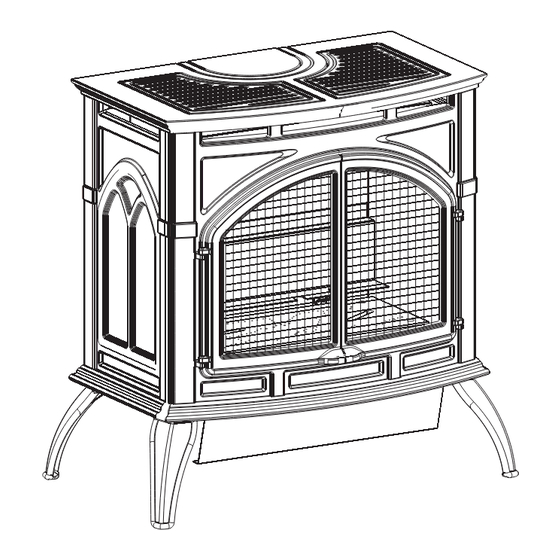
The Heritage Cast Iron Stoves
This appliance may be installed in an aftermarket,
permanently located, manufactured (mobile) home,
where not prohibited by local codes.
This appliance is only for use with the type of gas
indicated on the rating plate. This appliance is not
convertible for use with other gases.
WARNING: If the information in these instruc-
tions are not followed exactly, a fire or explosion
may result causing property damage, personal
injury or loss of life.
— Do not store or use gasoline or other flamma-
ble vapors and liquids in the vicinity of this or
any other appliance.
— WhAT TO DO IF yOU SMELL GAS
•
Do not try to light any appliance.
•
Do not touch any electrical switch; do not
use any phone in your building.
•
Immediately call your gas supplier from a
neighbor's phone. Follow the gas suppli-
er's instructions.
•
If you cannot reach your gas supplier, call
the fire department.
— Installation and service must be performed by
a qualified installer, service agency or the gas
supplier.
INSTALLATION INSTRUCTIONS
OWNER'S MANUAL
GAS-FIRED
AND
CAST IRON
UNVENTED ROOM hEATER
MODELS
VFP30CA30(B,F,M,S,W)N-3
VFP30CA30(B,F,M,S,W)P-3
Installer: Leave this manual with the appli-
ance.
Consumer: Retain
this
reference.
This is an unvented gas-fired heater. It uses air
(oxygen) from the room in which it is installed.
Provisions for adequate combustion and ventilation
air must be provided. Refer to page 7 .
WARNING: If not installed, operated and main-
tained in accordance with the manufacturer's
instructions, this product could expose you to
substances in fuel or from fuel combustion which
can cause death or serious illness.
WATER VAPOR: A By-PRODUCT OF
UNVENTED ROOM hEATERS
Water vapor is a by-product of gas combustion. An
unvented room heater produces approximately one
(1) ounce (30 ml) of water for every 1,000 BTU's
(.3KW's) of gas input per hour. Refer to page 6.
manual
for
future
Page 1
Advertisement
Table of Contents
Troubleshooting

Subscribe to Our Youtube Channel
Related Manuals for Empire Comfort Systems VFP30CA30 Series


Summary of Contents for Empire Comfort Systems VFP30CA30 Series
-
Page 1: Cast Iron
INSTALLATION INSTRUCTIONS EMPIRE EMPIRE OWNER'S MANUAL Comfort Systems The Heritage Cast Iron Stoves CAST IRON UNVENTED ROOM hEATER MODELS VFP30CA30(B,F,M,S,W)N-3 VFP30CA30(B,F,M,S,W)P-3 GAS-FIRED This appliance may be installed in an aftermarket, permanently located, manufactured (mobile) home, where not prohibited by local codes. This appliance is only for use with the type of gas indicated on the rating plate. -
Page 2: Table Of Contents
TABLE OF CONTENTS section Page iMPoRtant saFetY inFoRMation ................3 saFetY inFoRMation FoR UseRs oF LP-gas ............4 intRoDUction ........................5 sPeciFications .........................6 WateR VaPoR: a BY-PRoDUct oF UnVenteD RooM HeateRs ......6 PRoVisions FoR aDeQUate coMBUstion & VentiLation aiR .......7 gas sUPPLY .........................8 cLeaRances ........................9 aDJUsting aiR sHUtteR .....................10 Log PLaceMent ......................11... -
Page 3: Important Safety Information
IMPORTANT SAFETy INFORMATION ThIS IS A hEATING APPLIANCE Do not oPeRate tHis aPPLiance WitHoUt FRont PaneL instaLLeD. • An unvented room heater having an input rating of more than • WARNING: DO NOT operate this appliance unless 6,000 Btu per hour shall not be installed in a bathroom. all components including logs, burners, and controls •... -
Page 4: Safety Information For Users Of Lp-Gas
SAFETy INFORMATION FOR USERS OF LP-GAS Propane (LP-Gas) is a flammable gas which can cause fires by point with the members of your household. Someday when and explosions. In its natural state, propane is odorless and there may not be a minute to lose, everyone's safety will depend colorless. -
Page 5: Introduction
INTRODUCTION placement. Do not install unit with damaged, incomplete, or substitute Always consult your local Building Department regarding regulations, parts. Read all instructions before starting installation and follow these codes or ordinances which apply to the installation of an unvented instructions carefully during installation to insure maximum benefit room heater. and safety. Failure to follow them will void your warranty and may This appliance may be installed in an aftermarket* permanently present a fire hazard. located, manufactured (mobile) home, where not prohibited by state or local codes. The warranty will be voided by, and the warranter disclaims any *Aftermarket: Completion of sale, not for purpose of resale, from the responsibility for the following actions: manufacturer. • Installation of any damaged fireplace. This appliance is only for use with the type of gas indicated on the • Modification of the fireplace. rating plate. •... -
Page 6: Specifications
SPECIFICATIONS Model VFP30CA30(B,F,M,S,W) Accessories Input BTU/HR (KW/H) Maximum 32,000 (9.4) FRBc Battery Operated Remote Control BTU/HR (KW/H) Minimum 22,400 (6.6) FRBtc Battery Operated Remote Control w/Thermostat Height 27 3/4" (704.9 mm) FRBtP 7-Day Programmable Remote Width 28 1/16" (712.8 mm) FRec Electric Remote Control Depth 17 1/8" (435.0 mm) Wall Switch Gas Inlet 3/8" (9.5 mm) Millivolt Wall Thermostat - Reed Switch Remote Wall Thermostat Accessories Automatic Blower Shelf Kit - Includes both left & right shelves Stone Inlay Replaces Standard Grill Top csk-B Porcelain Black csi-8V Stone Inlay Venetian Gold csk-F Matte Black csi-9a Stone Inlay Adobe Frost csk-M Porcelain Mahogany... -
Page 7: Provisions For Adequate Combustion & Ventilation Air
PROVISIONS FOR ADEqUATE COMBUSTION & VENTILATION AIR This heater shall not be installed in a confined space or unusually Warning: If the area in which the heater may be operated is smaller tight construction unless provisions are provided for adequate than that defined as an unconfined space or if the building is of combustion and ventilation air. unusually tight construction, provide adequate combustion and ventilation air by one of the methods described in the National The National Fuel Gas Code, ANSI Z223.1 defines a confined space Fuel Gas Code, ANSI Z223.1/NFPA 54, Air for Combustion and as a space whose volume is less than 50 cubic feet per 1,000 Btu per Ventilation, or applicable local codes. -
Page 8: Gas Supply
GAS SUPPLy Check all local codes for requirements, especially for the size and type of gas supply line required. Recommended Gas Pipe Diameter Pipe Length Schedule 40 Pipe Tubing, Type L Inside Diameter Outside Diameter Nat. L.P. Nat. L.P. 0-10 feet 1/2” 3/8” 1/2” 3/8” 0-3 meters 12.7 mm 9.5 mm 12.7 mm 9.5 mm 10-40 feet 1/2” 1/2” 5/8” 1/2” 4-12 meters 12.7 mm 12.7 mm 15.9 mm 12.7 mm 40-100 feet 1/2” 1/2” 3/4”... -
Page 9: Clearances
CLEARANCES 4” (102mm) HEATER CORNERS Clearances (Figures 2, 3, and 4) TO SIDE WALL When facing the front of the appliance the following minimum clearances to combustible construction must be maintained. Top of appliance (ceiling) 36 inches Rear Wall 2 inches Side Wall 6 inches Heater Corners (45° angle) to Wall 4 inches Floor 0 inches Provide adequate clearances around air openings. Adequate accessibility clearances for purposes of servicing and proper operation must be provided. Installation on Rugs and Tile This appliance must be installed on a flat, solid, continuous surface (e.g. wood, metal, concrete). This may be the floor, or it may be raised up on a platform to enhance its visual impact. The appli- ance may be installed on carpeting, vinyl, wood flooring or other... -
Page 10: Adjusting Air Shutter
aDJUsting aiR sHUtteR The air shutter has been factory set to the optimum performance level for this appliance. LP air shutter is not adjustable. 1. Remove cast iron top and carefully set aside. 2. Remove cast iron front and carefully set aside. 3. Remove screen door by removing two (2) screws. See Figure 4. Carefully remove logs and set aside. 5. Remove the log shelf by removing the two (2) screws securing the log shelf to the rear wall. See Figure 6. 6. Remove the burner by removing the two (2) screws at the front of the burner as shown in Figure 7. 7. Carefully remove the burner by lifting straight up. 8. Loosen the two (2) nuts on the air shutter shown in Figure 8 to adjust the air shutter. Figure 8 call-out demonstrates the proper locations for Natural Gas. LP utilizes a fixed air shutter. Figure 6 9. Tighten the two (2) nuts back down locking the air shutter in place. Be sure that the air shutter is the same distance from the burner orifice on both sides of the air shutter for proper burner fit up. 10. Carefully replace the burner by dropping it down over the orifice holder and air shutter lining up the front mounting holes with the holes on the firebox. -
Page 11: Log Placement
Log PLaceMent 1. Remove cast iron top and carefully set aside. LEFT TWIG RIGHT TWIG 2. Remove cast iron front and carefully set aside. 3. Remove two (2) screws from screen frame assembly. 4. Carefully remove screen frame assembly and set aside. 5. Remove logs from shipping crate. Remove all protective packaging from logs and interior of firebox. REAR LOG 6. Place rear log onto two (2) pins on rear log support. 7. Place center left front log onto flat portion of left side of burner. -
Page 12: Operating Guidelines
OPERATING GUIDELINES CAUTION: During the initial purging and subsequent lightings, Before operating this heater, please review the safety warnings never allow the gas valve control knob to remain depressed in pages at the beginning of this manual and those precautions and the "pilot" position without pushing the piezo ignitor button warnings listed below. -
Page 13: Lighting Instructions
LIGhTING INSTRUCTIONS FoR YoUR saFetY ReaD BeFoRe LigHting WARNING: IF yOU DO NOT FOLLOW ThESE INSTRUCTIONS EXACTLy, A FIRE OR EXPLO- SION MAy RESULT CAUSING PROPERTy DAMAGE, PERSONAL INJURy OR LOSS OF LIFE. A. This appliance has a pilot which must be lighted by hand. • If you can not reach your gas supplier, call the fire depart- When lighting the pilot, follow these instructions exactly. -
Page 14: Pilot Flame Characteristics
PILOT FLAME ChARACTERISTICS Cleaning and Maintenance/Pilot Figure 11 shows a correct pilot flame pattern. The correct flame Oxygen Depletion Sensor Pilot (Figure 13) will be blue and will extend beyond the thermocouple and ther- When the pilot has a large yellow tip flame, clean the Oxygen mopile. The flame will surround the thermocouple and thermopile Depletion Sensor as follows: just below the tip. A slight yellow flame may occur where the pilot 1. Clean the ODS pilot by loosening nut B from the pilot tubing. flame and main burner flame meet. Figure 12 shows an incorrect When this procedure is required, grasp nut A with an open pilot flame pattern. The incorrect pilot flame is not touching the wrench. -
Page 15: Main Burner Flame Characteristics
MAIN BURNER FLAME ChARACTERISTICS Cleaning and Maintenance / Main Burner Figure 14 shows a correct main burner flame pattern. Figure 15 Warning: Turn off heater and let cool before cleaning. shows an incorrect main burner flame pattern. After use, cleaning of the main burner may be required for the If main burner flame pattern is incorrect, as shown in Figure 15: proper flame. The main burner may be cleaned by applying air • See Troubleshooting, pages 18 and 19. pressure to the ports on the main burner. Cleaning the Log Set and Firebox CAUTION: Do not handle these logs with your bare hands. -
Page 16: Wiring
WIRING ON/OFF/REMOTE Switch Wiring of ON/OFF/REMOTE Switch with 750 Millivolt Wall This product is equipped with an ON/OFF/ReMote switch which Thermostat Accessory and Another Accessory is located on the wire channel. A wire harness is attached to the Connect the green and red, stripped and bare, wires on the ON/OFF/ ON/OFF/REMOTE switch. The red, black and green (wires) female REMOTE switch wire harness to the 750 millivolt wall thermostat AND to the remote receiver that is a component in the FRBC, FREC push-ons attach to the ON/OFF/REMOTE switch. At the opposite end of the wire harness, the black and green (wires) female push- OR to the FWS, wall switch. ons attach to the gas valve. An additional green wire and the red 1. Connect (1) wire from the 750 millivolt wall thermostat and (1) wire, which are stripped and bare, will attach to the 750 millivolt wire from appropriate accessory to the GREEN, stripped and wall thermostat accessory, or, to one of the other accessories that bare wire from the ON/OFF/REMOTE wire harness. 2. Connect (1) wire from the 750 millivolt wall thermostat and (1) can be purchased for use with your log set. wire from appropriate accessory to the RED, stripped and bare Operation of ON/OFF/REMOTE Switch with no Accessories wire from the ON/OFF/REMOTE wire harness. -
Page 17: Maintenance
WIRING (continued) Wiring Diagram REMOTE CONTROL RECEIVER/ THERMOSTAT/ CONTROLE E WIRING DIAGRAM DISTANCE DU RECEPTEUR (OPTIONAL) THERMOSTAT (FACULATIVE) THERMOSTAT GAS VALVE (OPTIONAL) WALL SWITCH VALVE DE GAZ INTERRUPTEUR MURAL REMOTE/OFF/ON SWITCH (FACULTATIVE) A DISTANCE/OUVERT/ FERME INTERRUPTEUR (OPTIONAL) REMOTE CONTROL RECEIVER (FACULTATIVE) CONTROLE E DISTANCE DU RECEPTEUR REMOTE/OFF/ON SWITCH... -
Page 18: Troubleshooting
TROUBLEShOOTING sYMPtoMs - PossiBLe caUses anD coRRections iMPoRtant: Operating heater where impurities in air exist may create odors. Cleaning supplies, paint, paint remover, cigarette smoke, cements and glues, new carpet or textiles, etc., create fumes. These fumes may mix with combustion air and create odors. 5. Pilot burning, no gas to burner, valve knob "ON", on/off 1. When ignitor button is pressed, there is no spark at ODS/ switch "ON." pilot. a. "On/Off" switch, wall switch, remote control or wires a. Ignitor electrode positioned wrong - Replace ignitor. -
Page 19: How To Order Repair Parts
Foreign matter between logs and main burner - remove burner is lit or shut off. foreign matter. a. Metal expanding while heating or contracting while cooling b. Gas leak - Locate and correct all leaks. - This is common with most heaters. If noise is excessive, contact service person. hOW TO ORDER REPAIR PARTS Parts can be ordered only through your service person or dealer. For best results, the service person or dealer should order parts through the distributor. Parts can be shipped directly to the service person/dealer. All parts listed in the Parts List have a Part Number. When ordering parts, first obtain the Model Number from the name plate on your equipment. Then determine the Part Number (not the Index Number) and the Description of each part from the following appropriate illustration and list. Be sure to give all this information. Heater Model Number Heater Serial Number Part Number Part Description Type of Gas (Propane or Natural) Do not order bolts, screws, washers or nuts. They are standard hardware items and can be purchased at any local hardware store. Shipments contingent upon strikes, fires and all causes beyond our control. Empire Comfort Systems, Inc. Nine Eighteen Freeburg Ave. Belleville, Illinois 62222-0529 26563-0-0410 Page 19... -
Page 20: Parts List
PARTS LIST PLEASE NOTE: When ordering parts, it is very important that part number and description of part coincide. INDEX NO. PART NO. DESCRIPTION 15484 oUtLet BaFFLe 24043 FIREBOX BRACE (2 REQUIRED) 23938 FiReBoX toP 24034 FiReBoX WaLLs 24017 ReaR Log sUPPoRt 15567 scReen FRaMe asseMBLY R-3624 PiLot asseMBLY - nat R-3623 PiLot asseMBLY - LPg 24560 PiLot BRacket 26562 BURneR asseMBLY P-253... -
Page 21: Parts View
PARTS VIEW 26563-0-0410 Page 21... -
Page 22: Casting Parts List
casting PaRts List PLEASE NOTE: When ordering parts, it is very important that part number and description of part coincide. INDEX PART DESCRIPTION INDEX PART DESCRIPTION COMMON PARTS PORCELAIN BLACK R-9671 INSERT TAB (4 REQUIRED) R-9571 Vent oPening inseRt R-9669 HINGE PIN (4 REQUIRED) R-9570 toP inseRt - RigHt R-9670 BOLT, 1/4-20 X 1/2” (24 REQUIRED) R-9569 toP inseRt - LeFt MATTE BLACK R-9568 casting toP R-9539 Vent oPening inseRt R-9681 casting FRont... -
Page 23: Casting Parts View
casting PaRts VieW 26563-0-0410 Page 23... -
Page 24: Accessory Side Shelves Installation Instructions
accessoRY siDe sHeLVes instaLLation instRUctions Installing Accessory Side Shelves: 8. Attach side shelf supports one at a time, using (2) ¼-20 hex 1. Remove cast iron or stone inlay inserts from casting top and head bolts per support, sliding support flush to casting before carefully set them aside. fully tightening bolts as shown in Figure 20. 2. Remove cast iron top from stove and place upside down on a 9. Replace cast iron or stone inlay inserts into casting top. flat, soft smooth surface to avoid damage. 3. Remove (4) ¼-20 hex head bolts from the outer edges of cast Note: Be sure to remove side shelf supports prior to removing iron top. cast iron top to eliminate potential scratching or chipping to the 4. Place left and right side shelves in place shown in Figure 19. cast iron sides. 5. Replace (4) ¼-20 hex head bolts to attach side shelves to Note: Due to inherent properties of the casting process, non-com- cast iron top, be sure shelf is tight to casting top before fully bustible shims may be required to level accessory side shelves to... -
Page 25: Optional Blower Installation Instructions
oPtionaL BLoWeR instaLLation instRUctions Installing Optional CIB3 Blower 10. Install rheostat through hole in wire channel and align small 1. Loosen, but do not remove, four (4) hex-head screws located tab with small hole. on the exterior, bottom of the appliance. 11. Use an 11/16” wrench to tighten rheostat nut on stationary 2. Position the blower assembly at the rear of the appliance. The portion of knob stem of the rheostat. Note: Nut is self-tapping blower assembly has four (4) keyholes for attachment to the and can be started at an angle. exterior, bottom of the appliance. 12. Push rheostat knob onto knob stem until fully seated. 3. Place the large diameter holes in the keyholes over and behind 13. Bend the fan control tab, located on the left side of the back the four (4) hex-head screws that were loosened in Step 1. of the unit, inward toward the unit. See Figure 23. Be sure tab Push inward on the blower assembly to lock the keyholes into is bent at least 90 degrees to allow fan control bracket to slide... - Page 26 oPtionaL BLoWeR instaLLation instRUctions Cleaning CAUTION: Label all wires prior to disconnection when servicing The blower wheel will collect lint and could require cleaning once controls. Wiring errors can cause improper and dangerous a year. If the air output decreases or the noise level increases, it operation. Verify proper operation after servicing. indicates a dirty wheel. Blower Motor The blower motor does not have oiling holes. Do not attempt to WARNING: oil blower motor. Unplugging of blower accessory will not stop the heater from cycling. To shut heater off: Turn temperature dial or Wiring thermostat to lowest setting.
-
Page 27: Optional Blower Installation Instructions
oPtionaL BLoWeR instaLLation instRUctions PARTS LIST INDEX PART DESCRIPTION NUMBER NUMBER R-1454 BRass BUsHing R-1499 RUBBeR gRoMMet 24231 BLoWeR HoUsing R-1410 stRain ReLieF BUsHing R-9927 BLoWeR asseMBLY 24225 BLoWeR coVeR R-6159 coRD set R-9699 WiRe HaRness R-2503 Fan contRoL 24222 Fan contRoL BRacket R-2805 AUTO OFF/ON SWITCH... -
Page 28: Service Notes
seRVice notes Page 28 26563-0-0410... - Page 29 seRVice notes 26563-0-0410 Page 29...
- Page 30 seRVice notes Page 30 26563-0-0410...
-
Page 31: Quick Reference
Web Site: www.empirecomfort.com Empire Comfort Systems EMPIRE EMPIRE 918 Freeburg Avenue Belleville, Illinois 62220-2623 Comfort Systems The Heritage Cast Iron Stoves Models: VFP30CA30B, VFP30CA30F, VFP30CA30M, VFP30CA30S, VFP30CA30W Specifications Model VFP30CA30(B,F,M,S,W) Input BTU/HR (KW/H) Maximum 32,000 (9.4) BTU/HR (KW/H) Minimum 22,400 (6.6) Height 27 3/4"... - Page 32 Empire Comfort Systems Inc. EMPIRE EMPIRE 918 Freeburg Ave. Belleville, IL 62220 PH: 618-233-7420 or 800-851-3153 FAX: 618-233-7097 or 800-443-8648 info@empirecomfort.com Comfort Systems www.empirecomfort.com Page 32 26563-0-0410...
Need help?
Do you have a question about the VFP30CA30 Series and is the answer not in the manual?
Questions and answers