Table of Contents
Advertisement
WARNING: If the information in this
manual is not followed exactly, a fire
or explosion may result causing prop-
erty damage, personal injury or loss
of life.
— Do not store or use gasoline or other
flammable vapors and liquids in the
vicinity of this or any other appliance.
— WHAT TO DO IF YOU SMELL GAS
•
Do not try to light any appliance.
•
Do not touch any electrical switch;
do not use any phone in your build-
ing.
•
Immediately call your gas supplier
from a neighbor's phone. Follow
the gas supplier's instructions.
•
If you cannot reach your gas sup-
plier, call the fire department.
— Installation and service must be per-
formed by a qualified installer, service
agency or the gas supplier.
R-2688
INSTALLATION INSTRUCTIONS
OWNER'S MANUAL
AND
UNVENTED
ROOM HEATER
MODEL
EE-25-2
EFFECTIVE DATE
APRIL, 2001
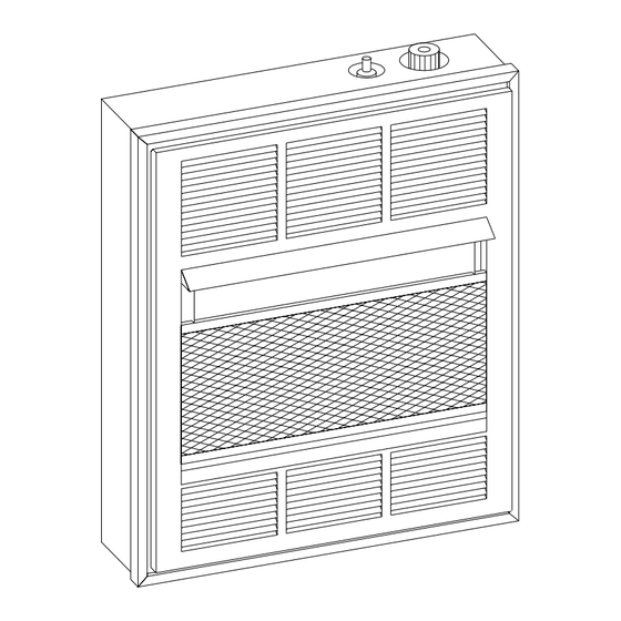
This is an unvented gas-fired heater. It
uses air (oxygen) from the room in which
it is installed. Provisions for adequate com-
bustion and ventilation air must be pro-
vided. Refer to page 6.
WARNING: If not installed, operated and
maintained in accordance with the manu-
facturer's instructions, this product could
expose you to substances in fuel or from
fuel combustion which can cause death or
serious illness.
WATER VAPOR: A BY-PRODUCT OF
UNVENTED ROOM HEATERS
Water vapor is a by-product of gas
combustion. An unvented room heater
produces approximately one (1) ounce
(30ml) of water for every 1,000 BTU's
(.3KW's) of gas input per hour. Refer to
page 6.
Page 1
Advertisement
Table of Contents

Related Manuals for Empire Comfort Systems EE-25-2


Summary of Contents for Empire Comfort Systems EE-25-2
-
Page 1: Installation Instructions
INSTALLATION INSTRUCTIONS OWNER'S MANUAL UNVENTED ROOM HEATER MODEL EE-25-2 WARNING: If the information in this EFFECTIVE DATE manual is not followed exactly, a fire APRIL, 2001 or explosion may result causing prop- erty damage, personal injury or loss of life. This is an unvented gas-fired heater. -
Page 2: Table Of Contents
TABLE OF CONTENTS SECTION PAGE Important Safety Information ........................3 Safety Information for Users of LP Gas ..................... 4 Introduction ..............................5 Specifications ............................. 5 Water Vapor: A By-Product of Unvented Room Heaters ................6 Provisions for Adequate Combustion and Ventilation Air ................. 6 Gas Supply .............................. -
Page 3: Important Safety Information
IMPORTANT SAFETY INFORMATION THIS IS A HEATING APPLIANCE DO NOT OPERATE THIS APPLIANCE WITHOUT FRONT PANEL INSTALLED. • An unvented room heater having an input rating of more • Installation and repair should be done by a QUALIFIED than 10,000 Btu per hour shall not be installed in a SERVICE PERSON. -
Page 4: Safety Information For Users Of Lp Gas
SAFETY INFORMATION FOR USERS OF LP-GAS Propane (LP-Gas) is a flammable gas which can cause fires by point with the members of your household. Someday when there may not be a minute to lose, everyone's safety will and explosions. In its natural state, propane is odorless and colorless. -
Page 5: Introduction
INTRODUCTION Instructions to Installer Important Installer must leave instruction manual with owner after All correspondence should refer to complete Model No., Serial installation. No. and type of gas. 2. Installer must have owner fill out and mail warranty card Notice: During initial firing of this unit, its paint will bake out, and supplied with unvented room heater. -
Page 6: Water Vapor: A By-Product Of Unvented Room Heaters
WATER VAPOR: A BY-PRODUCT OF UNVENTED ROOM HEATERS Water vapor is a by-product of gas combustion. An unvented The following steps will help insure that water vapor does not room heater produces approximately one (1) ounce (30ml) of become a problem. water for every 1,000 BTU's (.3KW's) of gas input per hour. -
Page 7: Gas Supply
GAS SUPPLY The gas line can be routed either through the floor or wall. The gas gas inlet. This should consist of a vertical length of pipe tee line opening should be made at this time. Location of the opening connected into the gas line that is capped on the bottom in which will be determined by the position of floor joists and the valve and condensation and foreign particles may collect. -
Page 8: Clearances
CLEARANCES When facing the front of the appliance the following minimum clearances to combustible construction must be maintained. Left side 5 inches (127mm). Right side 5 inches (127mm). Do not install in alcove or closet. Rear wall 0 inches (0mm). Ceiling 36 inches (914mm). Floor (top surface of carpeting, tile, etc.) 2 inches (51mm). -
Page 9: Wall Mount Installation
WALL MOUNT INSTALLATION On Sheet Rock Wall Refer to Figure 7 for measurements in order to locate (3) mount- 1. After locating mounting holes, drill (3) 5/16" (8mm) ing holes on wall. Figure 7 is the front view of the heater. diameter holes into the wall. -
Page 10: Lighting Instructions
LIGHTING INSTRUCTIONS FOR YOUR SAFETY READ BEFORE LIGHTING WARNING: If you do not follow these instructions exactly, a fire or explosion may result causing property damage, personal injury or loss of life. A. This appliance has a pilot which must be lighted by •... -
Page 11: Main Burner Flame Characteristics
MAIN BURNER FLAME CHARACTERISTICS There will be a short blue inner flame with a much larger lighter blue secondary flame. The burner flame may have a small yellow tip when hot. Dust in the combustion air will produce an orange or red flame. -
Page 12: Thermostat Operation
THERMOSTAT OPERATION To ignite main burner, rotate gas control knob counterclockwise The LO and HI setting has temperature range of approximately toward HI setting. To shut down main burner, rotate gas control 55 F (12.78 C) to 90 F (32.22 C), respectively. This is the knob clockwise toward LO setting. -
Page 13: Parts List
PARTS LIST PLEASE NOTE: When ordering parts, it is very important that part number and description of part coincide. Index Part Index Part Number Description Number Description R-1981 Piezo Ignitor VF-150 Frame Assembly VF-167 Casing Assembly R-1945 Ignitor Wire SR-113 Valve Bracket 732063 Electrode... -
Page 14: Parts View
PARTS VIEW Page 14 R-2688... -
Page 15: Optional Blower Installation Instructions
OPTIONAL BLOWER INSTALLATION INSTRUCTIONS EEB-1 for Unvented Room HeaterModel EE-25-(1, 2) INSTALLING OPTIONAL BLOWER EEB-1. If heater is 8. Remove #8 x 3/8" (10mm) screw from switch box cover and installed on wall, in order to install optional blower, the remove switch box cover from switch box. -
Page 16: Optional Blower Installation Instructions
OPTIONAL BLOWER INSTALLATION INSTRUCTIONS (continued) Wiring The appliance, when installed, must be electrically grounded in accordance with local codes or, in the absence of local codes, with the National Electrical Code ANSI/NFPA No. 70, if an external electrical source is utilized. This appliance is equipped with a three-prong [grounding] plug for your protection against shock hazard and should be plugged directly into a properly grounded three-prong receptacle.
Need help?
Do you have a question about the EE-25-2 and is the answer not in the manual?
Questions and answers