
Subscribe to Our Youtube Channel
Related Manuals for nexstyle 654OSA009STS


Summary of Contents for nexstyle 654OSA009STS
-
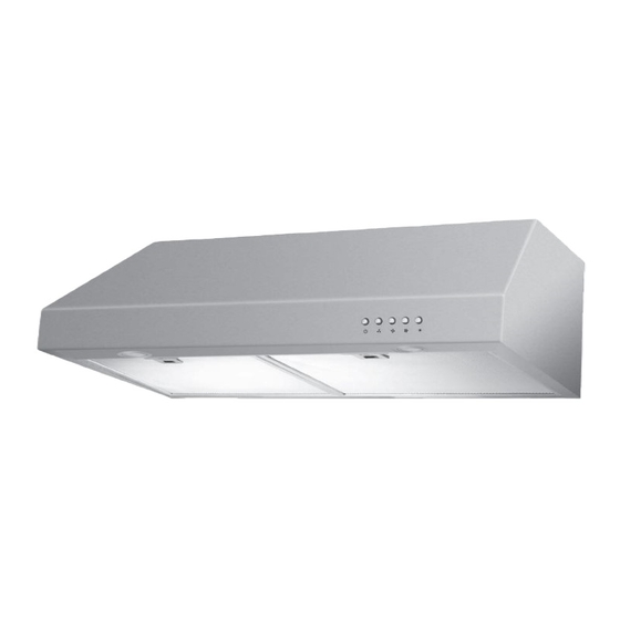
Page 1: Stainless Steel
Model#: 654OSA009STS Installation Guide and User Manual Please read and save this guide before using your range hood. Store the guide in a safe place so you will know where it is when you want to refer to it. -
Page 2: Do Not Return The Unit To The Place Of Purchase
IMPORTANT Carefully check the unit prior to installation to ensure there is no damage. Do not dispose of any packaging until you are satisfied with your new range hood. If you have any problems with this unit or there are missing or damaged parts, please call toll free: 1-800-459-4409 DO NOT RETURN THE UNIT TO THE PLACE OF PURCHASE... -
Page 3: Important Safety Instructions
IMPORTANT SAFETY INSTRUCTIONS Read all instructions before installing and operating this appliance. INSTAllATION Do not install if the appliance is damaged. 1. The instructions in this manual are intended for qualified installers, service technicians or other qualified persons. NEVER attempt to install this appliance yourself. -
Page 4: Safety Note
ClEANINg Do not operate blowers when filters are removed. 1. The saturation of greasy residue in the blower and filters may cause increased flammability. Keep this appliance clean and free of grease and residue build-up at all times to prevent possible fires. 2. -
Page 5: Before You Start
BEFORE YOU START... It is very important for your safety and the safety of others that you follow the many important safety messages in this manual and on your appli- ance. Always read and obey all safety messages. All safety messages will tell you what the potential hazard is, how to reduce the possibility of injury, and what can happen if the instructions are not followed. - Page 6 6) Ducted fans must always be vented to the outdoors. WARNING: To reduce the risk of fire, use only metal duct work. CAUTION: For general ventilation use only. Do not use the range hood fans to exhaust hazardous or explosive vapours. WARNING : To reduce the risk of injury in the event of a range top grease fire, observe the following: (Based on “kitchen fire safety tips”...
-
Page 7: Grounding Instructions
WARNING: FOR GENERAL VENTILATION USE ONLY. DO NOT USE THIS RANGE HOOD TO VENTILATE HAZARDOUS OR EXPLOSIVE MATERIAL AND VAPOURS. TO REDUCE THE RISK OF A RANGE TOP GREASE FIRE: 1) Never leave range unattended when in use. 2) Boil overs cause smoking and greasy spillovers that may ignite. 3 Heat oils slowly on low or medium setting. -
Page 8: Electrical Requirements
ElECTRICAl REQUIREMENTS OBSERVE ALL GOVERNING CODES AND ORDINANCES IMPORTANT: It is the customer’s responsibility to contact a qualified electrical installer and assure that the electrical installation is adequate and complies with the National Electrical Code, or CSA standards and all local codes and ordinances. - Page 9 9. When cutting or drilling into the wall or ceiling, do not damage electrical wiring and other hidden utilities. 10. Wire sizes must conform to the requirements of the National Electrical Code ANSI/NFPA 70 - latest edition*, or CSA Standards C22.1-94, Canadian Electrical Code Part 1 and C22.2 No.
-
Page 10: List Of Materials
lIST OF MATERIAlS TOOLS FOR INSTALLATION: powered screwdriver utility knife level or drill measuring tape flat-blade screwdrivers adjustable marker or wrench Philips pencil tape screwdrivers needle nose hammer pliers Notice: 1. Remove the range hood from the carton packaging and place on a flat surface for assembly. -
Page 11: Supplied Parts
SUPPLIED PARTS: Description Qty. Range Hood (with 2 filters) Damper (located inside the hood) ø4 mm x 8 mm tapping screw ø5 mm x 30 mm tapping screw Installation Guide installation guide range hood x 1 ø5 mm x 30 mm tapping screw x 4 ø4 mm x 8 mm tapping screw x 2 damper x 1... -
Page 12: Planning For Installation
PlANNINg FOR INSTAllATION WARNING * Proper installation is your responsibility - Have a qualified technician install this range hood. * Read the entire installation guide and user manual thoroughly, and understand instructions and warnings. * PERSONAL INJURY HAZARD - Because of the weight and size of the range hood, two or more people are needed to move and safely install the range hood. -
Page 13: Operation Test
Ceiling Range Hood Min: 61 cm (24 in) Height Max: 76.2 cm (30 in) Appox. 91.4 cm (36 in) OPERATION TEST: Before permanently mounting the range hood, temporarily wire the range hood and test for proper operation. If the rangehood is not operating correctly do not continue with the installation. - Page 14 OUTDOOR VENTING METHODS: This range hood can be top or back vented. Check to see which venting method you have. If this is a new installation, choose which venting method suits your needs. NOTE: Before making any cuts or holes for installation, carefully measure and mark all measurements.
- Page 15 IMPORTANT: - Vent system must terminate outdoors (through roof or side wall). - Do not terminate the vent system in an attic or any other enclosed area. - Use only metal/flexible aluminum vents. - Never use plastic vents. - Always keep ducts clean to ensure proper air flow. - NEVER exhaust air or terminate duct work between walls, crawl spaces, ceilings, attics or garages.
-
Page 16: Installation Instructions
Calculate the duct run length: If ducted with the required minimum of 15 cm (6 in.) round duct work, the duct run should not exceed 10.7 m (35 ft.). Calculate the length of the duct work by adding the equivalent feet as below for each piece of duct in the system. - Page 17 1. Determine the venting method (vertical top venting or horizontal back venting). 2. Use a hammer and flat tipped screwdriver to gently punch out the appropriate electrical knock-out hole (figure 1). Be very careful not to leave any broken pieces inside the range hood. Electrical knock-out hole Fig.
- Page 18 Top Venting Back Venting Fig.2 4. Install the damper with two 4mm x 8mm tapping screws (figure 3). If this hood replaces an existing unit, the location of the air exhaust can vary from one manufacturer to another. Make sure the damper fits in the existing opening before installing.
- Page 19 5. Seal the damper to the hood using duct tape (figure 4). Fig.4 6. Turn the hood upside down on a protective covering such as card- board or a large towel. Remove the 2 aluminum filters and bottom panel. (a) Remove the aluminum filters by pulling the handles.
- Page 20 8. Screw the four Ø 5 mm x 30 mm tapping screws into the pilot (0.28 in) holes. Leave screw heads about 7 mm (0.28 in) from the cabinet Fig.7 surface (figure 7). 9. Lift range hood into position, feeding electrical wires through wiring opening.
- Page 21 11. Connect the electrical wires from the range hood to the house wiring. Make sure you read and understand the electrical requirements section at the beginning of this manual. WARNING: All wiring should be done by or approved by a qualified electrician.
-
Page 22: Maintenance
MAINTENANCE Prior to any maintenance operation ensure that the range hood is discon- nected from the power supply. WARNING ELECTRICAL SHOCK HAZARD Do not perform service on an electrically live system. Disconnect the main electrical supply before servicing this device. Touching electrical connectors or other exposed electrical circuitry inside this range hood when they are energized could result in death, serious bodily injury, or property damage. -
Page 23: Replacing Filters
Cleaning aluminium filters: - The filters fitted by the factory are intended to filter out residue and grease from cooking. It need not be replaced on a regular basis but are required to be kept clean. - Do not accumulate oil over 80% of the filter surface to avoid oil dropping on range. -
Page 24: Operation
1. Turn off the range hood. 2. Ensure the lights are cool to the touch. 3. Turn bulb anti-clockwise to remove. 4. Install a new GU10 twist and lock base lamp (MAX. 25W/ Rotate anti-clockwise JDR 16) and turn clockwise and pull out to remove to install the light bulb. - Page 25 - Make sure the wiring between the switch board and control board are connected properly. 2. The range hood vibrates when the blower is on: - The range hood might not have been secured properly to the wall. - Check if the motor is secured in place. If not, then tighten the motor in place.
-
Page 26: Wiring Diagram
WIRINg DIAgRAM Yellow & Green Motor 25W/JDR 16 GU10 Capacitor Light White 5µ F/370V Black Black Black White White Black Grey SPECIFICATIONS 757mm (29-13/16 in) 706mm (27-3/4 in) 250mm (9-13/16 in) 28mm 22mm (7/8 in) 39mm (1-1/4 in) dia. hole (1-1/2 in) 18mm (11/16 in) - Page 27 PARTS Control Switch Damper Hood body Light Light Motor Bottom Panel Fan Guard Aluminium Filters...
- Page 28 1-YEAR HOME USE WARRANTY This product is warranted to the original purchaser to be free of defects in material and workmanship for one (1) year from the date of purchase. This warranty does not extend to commercial or institu- tional use or installation. Warranty service should be arranged through the point of purchase. The purchaser is responsible for transporting the unit to and from the point of purchase.
Need help?
Do you have a question about the 654OSA009STS and is the answer not in the manual?
Questions and answers
What is the measurements of replacing the filters?
The Nexstyle 654OSA009STS range hood requires aluminum grease filters with stainless steel clips for replacement. The specific measurements for these filters are not provided in the given context.
This answer is automatically generated