Table of Contents
Advertisement
Advertisement
Table of Contents

Summary of Contents for Mackenzie M2
-
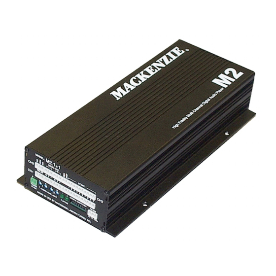
Page 1: Digital Audio Player
HIGH FIDELITY MULTI-CHANNEL DIGITAL AUDIO PLAYER User's Manual Version 1.1 Revised 12/23/2003 Doc 99-20-078 - $25.00 MACKENZIE LABORATORIES, INC. Tel: (909) 394-9007 Fax: (909) 394-9411 1163 Nicole Court Web: www.macklabs.com Glendora, CA 91740 USA Email: info@macklabs.com... - Page 2 Regulations: FCC (Part 15) Radio Frequency Interference The M2 generates and uses radio frequency energy and if not installed and used in strict accordance with the manufacturer's instructions, may cause interference to radio and television reception. Unit complies with the limits for Class A devices in accordance with the specifications in Subpart J of Part 15 of the FCC Rules.
-
Page 3: Table Of Contents
M2-SW, Composer software PCMCIA FLASH memory M2-RM-x - M2 rack mount packaging. 1U package contains power supply and houses up to 3 M2 modules. Must be ordered as a system, not field upgradable. M2 User's Manual V 1.0 Revised 4/21/2003... -
Page 4: Overview
.WAV files then converts them to MPEG. The MPEG files then may be copied to the a PCMCIA drive on the computer or downloaded directly to the M2 over the RS232 port Message playback is controlled by simple contact closures or by RS232 commands. Audio outputs are balanced and level is controlled via potentiometers. -
Page 5: General Specifications
No parity, 8 bits, 1 stop bit Relay Outputs: Playing Interface: Euro terminals Mechanical Wall Mount/Table top - 5.7"W x 12" L x 2.4" H Rack mount(optional) - 1U Chassis - aluminum extrusion, painted M2 User's Manual V 1.0 Revised 4/21/2003 Page 5... -
Page 6: Hardware Configurations
1.3.3. M2.2 Single Balanced Stereo audio channel, 20 message input selections, RS232, wall/table top mount package. Interfaces of M2.1 PLUS, Second Stop contact Start contacts 11 - 20 Second Input Common M2 User's Manual V 1.0 Revised 4/21/2003 Page 6... -
Page 7: Installation & Configuration
2. Installation & Configuration This section provides complete instructions for mounting the M2 High Fidelity Multi-Channel Digital Audio Player on a Wall or Table. It also illustrates all interface requirements to auxiliary equipment, including inputs and outputs. Configuration switch settings are provided. -
Page 8: Audio Level Adjust
Connect to common for message 10 playback Connecting any input to common activates the function 2.2.6. Playing LED Green LED which indicates the playing and boot status of the M2. M2 is not playing or no power supplied to the unit M2 is playing... -
Page 9: Config Switches
Position is ON This user adjustable dip switch is provided to allow the user to tailor the operation of the M2 to meet their demands. Note: This dip switch is read by the CPU only upon power up. Changing the position of the dip switch while the module is powered up will have no affect on the operation of the system. -
Page 10: Play Mode
Play one sequence per closure: If an activation input is maintained, the system will only play the message sequence one time. The M2 will wait for the input to go inactive for a preset amount of time before it will recognize that input for subsequent message activation. Other play activation will be serviced normally even with another input held active indefinitely. -
Page 11: Rs-232 Hardware Configuration
Transmit Ground 2.3. M2.1 Enhanced Configuration and Features: The M2.1 is the base model of the M2 family. All configuration and features for this model are covered in Section 2.2. 2.4. M2.1+1 Enhanced Configuration and Features: The M2.1+1 offers all the configuration and features of the base system with the addition of a second independent balanced stereo audio output and associated start contacts. -
Page 12: Ch 2, Relay
Connect to common for message 10 playback Connecting any input to common activates the function 2.4.5. CH 2, Playing LED Green LED which indicates the playing and boot status of the M2. M2 is not playing or no power supplied to the unit M2 is playing... -
Page 13: M2.2 Enhanced Configuration And Features
2.5. M2.2 Enhanced Configuration and Features: The M2.2 offers all the configuration and features of the base system with 10 additional start inputs. Contacts 11 - 20 are located above 1 - 10. 2.5.1. Remote Control, 11 - 20: 12 position pluggable terminal strip. Use for remote control start of message playback and stopping messages. - Page 14 If “XXXX” is in the location, the message is currently blank, and the location is available. If a “D” is in front of the message number, a message exists, but it is disabled and not available for playback. LST - This command lists the commands available to control the M2. Syntax; Example;...
- Page 15 STP - Stop message playback Syntax; STPchannel Where; channel is the channel, 1 or 2 or A(M2.1+1 only), that you want to stop. Entering no channel value or A(ALL) stops all channels from playing. Example; STP1<CR><LF> will stop message playback on channel 1.
- Page 16 NOTE: MUST BE IN QUOTES Example; DDEL"1.mpg"<CR><LF> deletes 1.mpg from memory card. DDLD - This command configures the M2 to receive a MPEG 1 Layer 2 file via YMODEM. Syntax; DDLDmsgnumber Where;...
-
Page 17: Playing - Rs-232
This process is valid for any message(1 - 255) that has a corresponding .MPG file on the memory card. M2 will report an error for a message request which does not have a corresponding .MPG file. Play relay contact will be active for the duration of play sequence. -
Page 18: Playing - Remote Contact
This process is valid for any Start input which has a corresponding .MPG file on the memory card. M2 will ignore an input which does not have a corresponding .MPG file. Play relay contact will be active for the duration of play sequence. -
Page 19: Composer
Browse the available disk drives, including mapped drives View the available WAV files in a folder Drag and drop WAV files into the Snippet section for compilation into an M2 memory. Delete / Add / Insert WAV files into the Snippet section. -
Page 20: Encoding Functions
Typically, this will be used to point to the PC Card drive where the M2 Memory card would be burned. If the User Double Left clicks a snippet in the snippet section, the Snippet properties screen will pop-up. - Page 21 Composer software uses the WAV file in the location specified to create an MPEG copy of the file for use with the M2. If the Source WAV file is moved, or deleted, the composer will not be able to re-encode that file. Checking this box causes the system to create a numbered copy of the WAV file in the CMACData folder for backup purposes.
-
Page 22: Memory Card Removal/Installation
The M2 utilizes removeable PCMCIA FLASH memory cards to store audio and configuration information. The image below illustrates how the card interfaces with the M2. The memory of the M2 is hot swappable and may be removed or installed without removing power from the system.
Need help?
Do you have a question about the M2 and is the answer not in the manual?
Questions and answers