Table of Contents
Advertisement
Quick Links
Advertisement
Table of Contents

Subscribe to Our Youtube Channel
Related Manuals for Paradise Datacom 4 RU Chassis


Summary of Contents for Paradise Datacom 4 RU Chassis
- Page 1 4 RU Chassis Solid State Power Amplifier Operations Manual Teledyne Paradise Datacom LLC Phone: (814) 238-3450 328 Innovation Blvd. Fax: (814) 238-3829 State College, PA 16803 USA Web: www.paradisedata.com Email: sales@paradisedata.com 201627 REV X ECO 16725 01/31/2012...
- Page 2 (SSPAs), Low Noise Amplifiers (LNAs), Block Up Converters (BUCs), and Modem products. Operating out of two primary locations, Witham, United Kingdom, and State College, PA, USA, Teledyne Paradise Datacom has a 20 year history of providing innovative solutions to enable satellite uplinks, battlefield communications, and cellular backhaul.
-
Page 3: Table Of Contents
Table of Contents Table of Contents ............................3 Section 1: General Information ....................... 9 1.0 Introduction ..........................9 1.1 Description ..........................9 1.2 Specifications ........................10 1.3 Equipment Supplied ......................10 1.4 Inspection ..........................10 1.5 Rack Mounting ........................10 1.6 Shipment.......................... - Page 4 2.2.1.4 Sys Info Page 4 ..................28 2.2.1.5 Sys Info Page 5 ..................28 2.2.1.6 Sys Info Page 6 ..................28 2.2.1.7 Sys Info Page 7 ..................29 2.2.1.8 Sys Info Page 8 ..................29 2.2.1.9 IP Info Page 1 ..................29 2.2.1.10 IP Info Page 2 ..................
- Page 5 2.4.1 Selecting the Master Unit ..................42 2.4.2 Controlling system operation ................. 43 2.4.3 N+1 Addressing ..................... 43 2.4.4 Adjust system gain ....................44 2.4.5 N+1 Automatic gain control option ................ 44 2.4.6 N+1 RF power measurements ................44 2.4.7 N+1 Fault Detection ....................45 2.5 Reflected Power Option ......................
- Page 6 5.4 Switch Connector ........................67 5.5 Link Cable ..........................68 5.6 Installation and SSPA Configuration ..................70 5.6.1 Installation ......................70 5.6.2 Setting SSPA Polarization priority ................. 71 5.7 Online/Standby Amplifier Selection ..................71 5.8 Auto vs. Manual switching mode ................... 72 5.9 Physically rotating transfer switch ..................
- Page 7 Appendix A: Ethernet Options Quick Set-Up ..................115 Appendix B: Proper 10/100 Base-T Ethernet Cable Wiring .............. 119 Appendix C: RM SSPA Control with Paradise Datacom Universal M&C ........123 Appendix D: Automatic Level Control ....................127 Appendix E: Documentation ....................... 129 Figures Figure 1-1: Solid State Power Amplifier Chassis RM Unit ............
- Page 8 Figure 7-5: Header Sub-Packet ....................82 Figure 7-6: Data Sub-Packet ....................... 83 Figure 7-7: Trailer Sub-Packet ....................86 Figure 7-8: Packet Wrapper technique ..................87 Figure 7-9: Terminal Mode Session Example ................97 Figure 7-10: UDP Redirect Frame Example ................99 Figure 7-11: Initializing Web Interface ..................
-
Page 9: Section 1: General Information
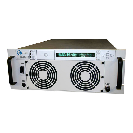
Section 1: General Information 1.0 Introduction This section provides the general information for the Teledyne Paradise Datacom Solid State Power Amplifier (SSPA) Chassis. This includes a description of the unit and safety precautions. 1.1 Description The Teledyne Paradise Datacom SSPA Chassis represents the latest in high power microwave amplifier technology. -
Page 10: Specifications
Perform a visual inspection of the equipment to make sure that all items on the packing list are enclosed. If any damage has occurred or if items are missing, contact: Teledyne Paradise Datacom LLC 328 Innovation Blvd. State College, PA 16803 USA... -
Page 11: Shipment
1.6 Shipment To protect the SSPA Chassis during shipment, use high quality commercial packing methods. When possible, use the original shipping container and its materials. Reliable commercial packing and shipping companies have facilities and materials to adequately repack the instrument. 1.7 Safety Considerations Potential safety hazards exist unless proper precautions are observed when working with this unit. -
Page 12: Rf Transmission Hazards
• Remove all conductive personal items (rings, watches, medals, etc.) • The work area should be secure and free of non-essential items. • Wear safety glasses and protective clothing. • Operators should never work alone on high risk devices. There should always be another person present in the same area to assist in the event of an emergency. - Page 13 • Operators should never work alone on hazardous equipment. There should always be another person present in the same work area to assist in the event of an emergency. • Operators should be familiar with procedures to employ in the event of an emergency, i.e., remove all power, CPR, etc.
- Page 14 THIS PAGE LEFT INTENTIONALLY BLANK 201627 REV X 4 RU SSPA Chassis Operations Manual...
-
Page 15: Section 2: Operation Of Stand-Alone Unit
Section 2: Operation of Stand-Alone Unit 2.0 Introduction This section contains operating information including a description of the front panel indicators and controls, and I/O connectors and their functions. 2.1 Description of Controls, Indicators and Connectors 2.1.1 Front Panel Features The RM SSPA has 10 LEDs to indicate the internal state of the amplifier. -
Page 16: Navigation Keys
2.1.1.2 Navigation keys Up, Down, Left, Right and Enter keys on the right side of the front panel allow menu navigation. 2.1.1.3 Standby Select key Functional only 1:1 Redundancy mode. Pressing this key will put designated HPA on standby. LED beside this key will turn on when HPA is Online. Key has no effect in Standalone mode and for standby HPA in 1:1 mode. -
Page 17: Rear Panel Features
RF OUT J2 MODEL: XXXXXXXXXXXX S/N: XXXX P/N: LXXXXXX-X AC IN Figure 2-2 - C-Band SSPA rear panel 2.1.2 Rear Panel Features Figure 2-2 shows an illustration of the rear panel view of a standard AC input Rack Mount chassis. The rear panel features the prime power connection, a removable Monitor &... -
Page 18: Dc Input Port (J10) (Option)
RF OUT J2 MODEL: XXXXXXXXXXXX S/N: XXXX P/N: LXXXXXX-X 48VDC INPUT Figure 2-3: SSPA Rear Panel, 48VDC Input Power (J10) 2.1.2.2 DC Input Port (J10) (Option) The SSPA Chassis can also be configured with a DC Input Voltage power supply. The DC Input Voltage can range from 42-60 VDC. -
Page 19: Figure 2-4: Optional N+1 Redundant External Power Supply
PARADISE DATACOM HPAK-2250 250W Ku-BAND POWER RF INPUT RF OUTPUT SAMPLE SAMPLE RF OUT J2 PS M&C MODEL: XXXXXXXXXXXX S/N: XXXX P/N: LXXXXXX-X -12VDC +12VDC Figure 2-4: SSPA with Optional N+1 Redundant External Power Supply 4 RU SSPA Chassis Operations Manual 201627 REV X... -
Page 20: Figure 2-5: Terminal Block
The power supply chassis has a dual feed AC architecture. Power module slots 0 & 1 are supplied via AC Feed 1 and power module slots 2 & 3 are supplied via AC Feed 2. The AC connections on the shelf are made via rear accessed compression style terminal blocks. -
Page 21: Rf Input Port (J1)
The alarm connection from each power supply chassis is parallel connected by supplied cable L206406-1. This cable also contains a current sharing line between the two power supply chassis. The power supply alarms may be monitored via the SSPA Chassis front panel menu. See Section 2.1.1.2. -
Page 22: Serial Main (J4)
2.1.2.7 Serial Main (J4) A DB9 female connector serves as primary remote control interface connector. The interface is re-configurable through the front panel or can be used as a RS-232 or RS-485 interface (2 or 4 wires). The RS-485 TX and RX pairs must be twisted for maximum transmission distance. -
Page 23: Table 2-3: Parallel Connector (37 Socket D Connector)
Table 2-3: Parallel connector (37 socket D connector) Pin # Function / Description Closed on Power Supply Fault Form C relay NC Opened on Power Supply Fault Form C relay NO Power Supply Fault Common 1. Standalone mode. Closed on Auxiliary Fault 2. -
Page 24: Hardware Mute (Tx Enable)
2.1.2.10a Hardware Mute (Tx Enable) There are three ways to mute the amplifier via hardware input: 1) A 50 ms closure to ground on Port J7, Pin 17 to toggle between Mute/Unmute states; 2) Select from the front panel Main Menu: 4.Fault Setup → 2. Auxiliary Faults → 1.Action →... -
Page 25: Removable Fan Assembly
2.1.2.13 Removable Fan Assembly The rear panel fan assembly can be removed for maintenance. See Section 3, Troubleshooting and Maintenance, for more details. 2.2 Menus Figure 2-7 shows the Front Panel Display Menu Structure hierarchy. There are six main levels of menu selections. 1. -
Page 26: System Information Sub-Menu
2.2.1 System Information Sub-Menu The informative sublevel menu structure contains several pages, shown in Figure 2-8. The user can also browse among these pages by navigating the cursor around the menu fields and pressing the Enter button on the keypad. Note that this function will not work if the "Fault Latch"... -
Page 27: Sys Info
2.2.1.1 Sys Info Page 1 This is the HPA main status information page. The page shows: • HPA attenuation measured in dB ( Atten. (dB): XX.X) with accuracy of 0.1dB; • Forward RF Power, measured in either dBm with resolution of 0.1dBm, or Watts with a resolution of 0.1 Watts, with a 20dBm dynamic range from the maximum rated output power;... -
Page 28: Sys Info
2.2.1.4 Sys Info Page 4 This page displays various HPA settings: • Prtcl. - current HPA remote control protocol. The value can be set to "Terminal", if terminal mode protocol is currently active and "Normal" for string I/O type protocol. •... -
Page 29: Sys Info
2.2.1.7 Sys Info Page 7 This page shows RF module related faults and conditions. • Regulator - RF module regulator low voltage fault. Values - "Fault" or "Normal"; • DC Current - low DC current fault. Values -"Fault" or "Normal"; •... -
Page 30: Ip Info
• LockIP – This address is used to increase the security measure for the IPNet protocol. The SSPA will answer a request which comes only from a specified IP address. Set this address value to 0.0.0.0 or 255.255.255.255 to disable this feature. -
Page 31: N+1 Master Info
2.2.1.16 N+1 Master info Page 1 This page can only be viewed when the SSPA unit is configured as the N+1 Master unit. The page also becomes the default startup page for the Master SSPA . Several parameters related to N+1 System operational parameters are displayed: •... -
Page 32: N+1 Master Info
2.2.1.18 N+1 Master info Page 2 This page displays additional N+1 system operation data, and can be accessed by pressing the up (▲) arrow button from the N+1 Master Info Page 1. This page is only accessible from the N+1 Master unit. •... -
Page 33: Communication Setup Sub-Menu
Main Menu 1.Sys Info 2.Com Setup 3.Operation 4.Flt. Setup 5.Options 6.Redundancy 1.Protocol 2.Baud Rate 3.Sys Addr 4.Interface 5.IP Setup 1 .. 255 1.Normal 2.Terminal 1.2400 2.4800 3.9600 4.19200 5.38400 1.RS232 2.RS485 3.IPNet 4.SNMP 1.IPInfo 2.LocalIP 3.Subnet 4.Gateway 5.LocalPort 6.More To IP Info Page 3.Lock IP 4.Web Password 1.Community Get... -
Page 34: Interface
Note: Changes in serial communication settings from the front panel are effective immediately. Changes to these parameters from serial interface require that the unit be reset in order to take effect. The units can be reset either by cycling power to the unit or by issuing a reset command from the front panel, options menu. -
Page 35: Operation Setup Sub-Menu
Main Menu 1.Sys Info 2.Com Setup 3.Operation 4.Flt. Setup 5.Options 6.Redundancy 1.Info 2.Buzzer 3.Mute 4.Sys.Mode 5.Attenuation 6.RF Units To SSPA Firmware Info Page 0 .. 20 dB 1.On 2. Off 1.dBm 2. Watts 1.On 2. Off 1.Standalone 2. 1:1 3. 1:2 Figure 2-11: Operation Setup Sub-Menu 2.2.3 Operation Setup Sub-Menu This menu, shown in Figure 2-11, allows the user to select system-specific options. -
Page 36: Fault Monitoring Setup Sub-Menu
Main Menu 1.Sys Info 2.Com Setup 3.Operation 4.Flt. Setup 5.Options 6.Redundancy MENU ITEM NOT ACTIVE UNDER N+1 OPERATION 1.BUC Fault 2. Aux. Faults 3. RFSw Faults 4.Fault Latch 5.Low RF / ALC 1.Enable 2.Disable 1.Action 2.Fault Logic 1.Action 2.Fault Logic 1.Fault 2.Alert 3.Fault+Mute... -
Page 37: Fault Latch
2.2.4.4 Fault Latch Determines the alarm reporting condition. A latched alarm will remain indicated on the front panel until the operator clears the alarm by pressing the “Enter” button. Unlatched alarms will allow the summary alarm indicator to stop displaying the alarm condition if the circumstance creating the alarm has been cleared or corrected. -
Page 38: Options Sub-Menu
Main Menu 1.Sys Info 2.Com Setup 3.Operation 4.Flt. Setup 5.Options 6.Redundancy 1.Backup 2.Restore 3.Lamp Test 4.Password 5.Fan Speed 6.Reset 1.User Settings 2.Fctry Settings 1.I/O Card Only 2.I/O Card & RF Module 1.Set 2.Clear 1.Low 2.High 3.Change 3.Auto 0..255 Figure 2-13: Options Sub-Menu 2.2.5 Options Sub-Menu This menu, shown in Figure 2-13, makes available functions to backup or restore settings, set a password or the brightness of the Front Panel Display, and test the LED... -
Page 39: Fan Speed
2.2.5.5 Fan Speed Allows the user to set the unit’s fan speed. Choices are Low, High and Auto. Note: This menu item has no effect on the 4RU SSPA Chassis. 2.2.5.6 Reset Allows the user to reset the SSPA controller hardware to activate certain settings. For example, when the IP Address is modified the SSPA must be reset for it to use the new IP Address. -
Page 40: Unit Status
2.2.6.4 Unit Status Allows user to select between HPA1, HPA2 and HPA3. 2.2.6.5 Priority Select For use in 1:2 redundant systems. Allows the user to select Polarity 1 or Polarity 2. 2.2.6.6 N+1 system operation parameters Under this set of menus, the user may select or adjust important N+1 options. 2.2.6.6.1 N+1 Array size This menu sets the type of N+1 system or disables N+1 operation for this unit. -
Page 41: N+1 Info
When Auto Gain is enabled, the system will automatically back off from maximum linear gain and reserve 5dB of attenuator range for gain compensation. When this option is enabled, the Master Unit default System Information page will display: AutoGain(dB):XX.X. 2.2.6.6.4 N+1 Info When selected, the menu shown in Figure 2-15 is displayed and used for N+1 system troubleshooting. -
Page 42: N+1 Operational Basics (Two Or More Units)
Note: With multi-module RM SSPA chassis configurations, the N+1 system will require fewer chassis to form a N+1 redundancy array. Examples of 4-way N+1 systems: 1 four-module 6RU, 7RU or 10RU chassis; 2 two-module 4RU or 3RU chassis; 4 one-module 4RU or 3RU chassis. 2.4 N+1 Operational Basics (two or more units) A system which utilizes two or more SSPA chassis in an N+1 configuration may be operated directly from the front panel as if it was a single very high power SSPA. -
Page 43: Controlling System Operation
Any unit that develops a major fault condition will be automatically muted to avoid any side effects of the faulted unit on overall system performance. The Master unit offers two extra informative menu screens for displaying system level information such as: System forward and reflected power levels, system wide gain or attenuation, amount of faulted SSPA chassis in the system, etc. -
Page 44: Adjust System Gain
See Section 4.3 for directions on changing the N+1 hierarchy of SSPAs in an active system. 2.4.4 Adjust system gain Nominal system gain with Auto Gain enabled is 65 dB; nominal system gain with Auto Gain disabled is 70 dB. To adjust the gain of the system, select the [MAIN MENU] key →... -
Page 45: N+1 Fault Detection
2.4.7 N+1 Fault Detection The N+1 system carries comprehensive fault detection logic. Each SSPA chassis proc- esses its internal fault conditions as if it was a standalone unit. All N+1 Slave units re- port any fault state to the Master unit, which is responsible for system wide fault state handling. - Page 46 THIS PAGE LEFT INTENTIONALLY BLANK 201627 REV X 4 RU SSPA Chassis Operations Manual...
-
Page 47: Section 3: Troubleshooting And Maintenance
Section 3: Troubleshooting and Maintenance 3.0 Troubleshooting Faults The Rack Mount SSPA has five fault condition LEDs on left side of the front panel which reflect a summary fault, and fault states for voltage, temperature, current and the amplifier’s power supply. Additional fault reporting is available via the front panel display readout. -
Page 48: Current Fault
• The user should check the booster board voltages on the front panel display. This can be found under the system information portion of the main menu on the front panel. The voltage should read approximately 28VDC for each of the fans in the SSPA. -
Page 49: Modular Sspa Architecture
3.1 Modular SSPA Architecture The Teledyne Paradise Datacom SSPA Chassis consists of a modular design, which allows for quick and easy maintenance and replacement in the event of a catastrophic failure of one of the SSPA components. -
Page 50: Sspa Module Removal
Figure 3-5: Remove fan to Figure 3-4: Rear panel fan assembly. access power connector. The exhaust fans on the rear panel are each secured by (4) captive thumb screws. To remove, loosen the screws and carefully remove the fan assembly from the chassis. Unplug the fan power cord from the connector. -
Page 51: Figure 3-6: Sspa Module Placements
Figure 3-6: SSPA Module placement: C-band single module, left top; C-band dual module, left bottom; Ku-band single module, right top; Ku-band dual module right bottom Each SSPA module is secured to the heat sink plate by ten (10) 6-32 x 1-3/8” socket head cap screws. -
Page 52: Removable Controller Card (Rear Panel)
Figure 3-8. This exposes the SSPA module programming connectors. 3.1.4 Firmware Upgrade Procedure Teledyne Paradise Datacom’s digital engineers continually strive to improve the performance of the RM SSPA software and firmware. As this occurs, software and firmware upgrades are made available. The following procedure describes how to install a firmware upgrade for a 4RU RM SSPA. -
Page 53: Required Hardware
• PC with native parallel port (LPT1; LPT2 and LPT3 are supported. If your PC LPT port is mapped to an unusual memory address and shows a number higher than 3, contact Teledyne Paradise Datacom LLC for support). Port must be configured for EPP/ECP or bidirectional mode;... -
Page 54: Figure 3-11: Command Prompt Console Window Showing Successful Upgrade
Figure 3-11: Command prompt console window showing successful upgrade (For example: prg_LPT1.bat for LPT1 parallel port) and run it. The batch file will open a Command prompt console window and execute the firmware update. Do not interfere with the program until the entire process is complete. An example screenshot is shown in Figure 3-11. -
Page 55: Changing N+1 Hierarchy
3.2 Changing N+1 hierarchy Normally, the hierarchical structure of the N+1 array must be set during initial system setup. However, the operator may change the N+1 addressing hierarchy at any time. To ensure uninterruptible system operation during such system maintenance, certain procedural steps must be followed. - Page 56 1. Locate the current Master unit and change its N+1 address value to “0”; 2. If the new unit has an unknown N+1 address or has not been configured for N+1 operation, turn off the Auto Gain option; 3. If the new unit has a known N+1 address in conflict with one of the current SSPA slave units, resolve it by changing address of the current Slave unit.
-
Page 57: Section 4: 1:1 Redundant Operation
4.0 Introduction This chapter describes how to configure and control a 1:1 redundant system, which consists of two Teledyne Paradise Datacom SSPAs and a waveguide/coaxial switch. Two RM SSPA units can be connected in a 1:1 redundant configuration, which can automatically switch to an operating amplifier if the on-line SSPA develops a system fault. -
Page 58: Figure 4-2: Rm Sspa 1:1 Redundant Systems
Legacy 4RU 1:1 Redundant System Figure 4-2: RM SSPA 1:1 Systems with 1RU N+1 Power Supplies & RCP2-1100 201627 REV X 4 RU SSPA Chassis Operations Manual... -
Page 59: Hardware
4.1 Hardware Two Teledyne Paradise Datacom Rack Mount SSPA units are used for a 1:1 redundant configuration. The units are connected to each other through a link cable, which allows the exchange of online/standby status between SSPAs. -
Page 60: Link Cable
Table 4-1: RF Switch Connector Wiring HPA1, P2 HPA2, P3 RF Switch, P1 Description Common +28V Pos 1 Pos 2 Figure 4-3: Outline Drawing, Switch Connector Cable 4.1.4 Link Cable The 9 pin socket J8 connector Link Port is used to link two Redundant SSPAs in order to pass online/standby status information between them. -
Page 61: Installation And Sspa Configuration
RF OUT J2 SWITCH PS M&C MODEL: XXXXXXXXXXXX S/N: XXXX CABLE P/N: LXXXXXX-X LINK CABLE PS M&C MODEL: XXXXXXXXXXXX S/N: XXXX P/N: LXXXXXX-X AC IN Figure 4-5: Cable Connection between SSPAs and Waveguide Switch 4.2 Installation and SSPA configuration The two RM SSPA units are designed to be installed in a standard EIA rack. Warning! Ensure the equipment rack is properly supported to prevent tipping forward when the amplifiers are extended on their slides. -
Page 62: Setting Sspa1 Unit Status
4.2.1.3 Setting SSPA1 unit status. 1. From SSPA front panel press the “Main Menu” key; 2. Select item “6.Redund.” and press “Enter” key; 3. Select item “4.Status” and press “Enter” key; 4. Select item “1.HPA” and press “Enter” key. Note: SSPA2 unit status must be set to HPA2. Repeat steps 4.2.1.1 through 4.2.1.3 for SSPA2. -
Page 63: Physically Rotating Transfer Switch
RF power exceeds 400 Watts. This particular problem becomes a critical issue if coaxial RF pass switches are used. In general, all Teledyne Paradise Datacom SSPAs are well protected against high reflected power conditions, which may take place during output microwave switchover. -
Page 64: Parallel Port Special Functions
4.2.6 Parallel Port special functions In 1:1 Redundant Mode, each SSPA chassis will change some of its parallel I/O functions to alternative functions. See Table 4-3 for details. Table 4-3: Parallel connector (37 socket D connector), Highlighting 1:1 Functions Pin # Function / Description Closed on Power Supply Fault Form C relay NC Opened on Power Supply Fault Form C relay NO... -
Page 65: Section 5: 1:2 Internal Redundancy
Operation of a 1:2 system with controller is more fully discussed in the Redundant Systems Controller Operations Manual, document number 205933. Teledyne Paradise Datacom also offers an internal 1:2 redundancy system, where the extra controller is not required and the state of the system is negotiated between all three HPAs over the redundancy link and switch cables. -
Page 66: Required Hardware
If you purchased your SSPA as a standalone unit or as part of a 1:1 system, consult with Teledyne Paradise Datacom to determine if the revision of digital controller is 1:2 enabled. 1:2 redundancy Mode, unit HPA status and polarization priority need to be selected on all connected HPAs. -
Page 67: Power Supply
The 6-pin connector J3, Molex P/N 43810-002 can be located on the SSPA rear panel. This connector is used to interface with the RF switches. Teledyne Paradise Datacom recommends the following parts to build a mating pair to this connector (all P/N by Molex): Pin Crimp: 39-00-0039;... -
Page 68: Link Cable
5.5 Link Cable The 9-pin male connector J8 Link Port is used to link an HPA with the other two redundant units in order to pass online/standby status information between them. The link cable is an asymmetrical crossover cable. Take care to match the labels on each cable with the HPA status of the units (i.e., plug cable end with label “HPA1”... -
Page 69: Figure 5-4: 1:2 System Wiring Diagram
J3 Switch Port J8 Link Port RF Switch 2 HPA1 J3 Switch Port J8 Link Port HPA2 RF Switch 1 J3 Switch Port J8 Link Port HPA3 Figure 5-4: 1:2 System Wiring Diagram 4 RU SSPA Chassis Operations Manual 201627 REV X... -
Page 70: Installation And Sspa Configuration
5.6 Installation and SSPA configuration 5.6.1 Installation All three SSPA units are designed to be installed in a standard EIA rack. Warning! Ensure the equipment rack is properly supported to prevent tipping forward when the SSPAs are extended on their slides. HPA3 should be located on the bottom of the rack, HPA2 should be located directly above HPA3 and HPA1 should be located above HPA2. -
Page 71: Setting Sspa Polarization Priority
5.6.2 Setting SSPA’s Polarization priority Polarization priority selection becomes very important in then case when two out of the three SSPAs have developed summary faults. In this occasion, the remaining online SSPA may redirect its output to support either polarization. This setting applies only for HPA1 and HPA2. -
Page 72: Auto Vs. Manual Switching Mode
5.8 Auto versus Manual switching mode Normal operating mode for a RM SSPA in 1:2 redundant configuration is “Auto”. This mode provides automatic detection of a SSPA fault and switchover to the operational SSPA. The system is also protected from operator error; selecting a faulted SSPA is not allowed. -
Page 73: Section 6: L-Band Operation
Section 6: L-Band Operation 6.0 Block Up Converter Overview Teledyne Paradise Datacom SSPAs are available with various L-Band up converter options. The primary up converter option is the Zero dBm Block Up Converter, ZBUC . The ZBUC block up converter is offered in four C-Band configurations, two Ku-Band options, and one X-Band model. -
Page 74: Figure 6-2: Schematic, Optional Block Up Converter
TO SSPA MODULE RF INPUT Figure 6-2: Schematic, Optional Block Up Converter The schematic of Figure 6-2 shows the electrical position of the block up converter. It is powered from a +15 VDC supply available from the Back Plane Board Assembly. The Block Up Converter is simply cascaded with the SSPA at the input of the amplifier. -
Page 75: Zbuc Converter Features
6.1 ZBUC Converter Features This section describes the features available in the new Teledyne Paradise Datacom ZBUC converter. The ZBUC converter is available as an option for the SSPA. The ZBUC converter is available in four C-Band models, two Ku-Band models and one X-Band model. -
Page 76: Smart Reference Technology
6.3 Smart Reference Technology Teledyne Paradise Datacom’s new ZBUC converter comes standard with smart refer- ence technology. Smart reference technology allows the system operator to change external system reference frequency without any system configuration required. The ZBUC converter will automatically sense and lock to any one of the following system reference frequencies: 10, 20, 25, and 50 MHz. -
Page 77: Typical System Configurations
6.4 Typical System Configuration This section shows the 4RU Rack Mount SSPB in a common system application. Figure 6-4 shows the Compact Outdoor used with a Teledyne Paradise Datacom PD25 Evolution Series L-Band Modem. Figure 6-4: SSPB Chassis with Evolution Series Modem 6.5 IFL Cable Considerations... - Page 78 THIS PAGE LEFT INTENTIONALLY BLANK 201627 REV X 4 RU SSPA Chassis Operations Manual...
-
Page 79: Section 7: Remote Control Interface
Section 7: Remote Control Interface 7.0 Overview A system which includes an SSPA can be managed from a remote computer over a variety of remote control interfaces (see Figure 7-1). Remote control interface stack 10Base-T IP Interface SNMP HTTP Web Serial Interface RS485 Protocols:... -
Page 80: Remote Control - Parallel
The SSPA subsystem units can also be accessed directly through a packet wrapping technique described in Section 7.3. Serial protocol format is set at no parity, 8 bit with 1 stop bit. Baud rate is selectable through the front panel. If using a Terminal mode protocol, the SSPA provides remote menu access through a HyperTerminal program or through an actual hardware terminal. -
Page 81: Ru Sspa Chassis Operations Manual 201627 Rev X
7.1.2 Control Inputs The parallel control inputs are opto-isolated inputs with pull up resistors. To trigger a remote input command, the input should be pulled to ground. The input does not need to be held to ground continuously but it is acceptable to do so. The input only need be pulled low for a minimum of 50 msec. -
Page 82: Serial Communication Protocol
7.2 Serial Communication Protocol This section describes the basic serial communication protocol between the SSPA and host computer. The amplifier will only respond to properly formatted protocol packets. The basic communication packet is shown in Figure 7-4. It consists of a Header, Data and Trailer sub-packet. -
Page 83: Data Packet
7.2.2 Data Packet The data sub-packet is comprised of 6 to 32 bytes of information. It is further divided into seven (7) fields as shown in Figure 7-6. The first six (6) fields comprise the com- mand preamble while the last field is the actual data. HEADER DATA TRAILER... -
Page 84: Data Tag
7.2.2.4 Data Tag The data tag specifies the type of internal resource of information needed to be ac- cessed on the amplifier. The data associated with certain tags is read only. Therefore, only the “Get” command byte would be associated with these data tags. The data tag byte values are given in Table 7-2. -
Page 85: Data Length
Table 7-3: Error Status Byte Values Error Code Name Byte Value Possible Cause No Errors Normal Condition, no errors detected Data Frame Too Big Specified Data length is too big for amplifier buffer to accept No Such Data Specified Data Address is out of bounds for this tag data Bad Value Specified value not suitable for this... -
Page 86: Trailer Packet
7.2.3 Trailer Packet 7.2.3.1 Frame Check The trailer component contains only one (1) byte called the Frame Check Sequence, shown in Figure 7-7. HEADER DATA TRAILER (4 bytes) (6-32 bytes) (1 byte) Frame Check Checksum (1 byte) Figure 7-7: Trailer Sub-Packet This field provides a checksum during packet transmission. -
Page 87: Access Sspa Subsystem Through Packet Wrapper Technique
7.3 Access SSPA subsystem through Packet Wrapper technique Features introduced in firmware version 4.03 allow send requests directly to a remote SSPA subsystem. In this mode, the RCP redirects requests from its Serial Main or Ethernet port to its Local serial port, connected to the SSPA (see Figure 7-8). Packet wrapper requests are associated with longer response times, which have to be accounted in the host M&C software. -
Page 88: Table 7-4: Request Frame Structure
Table 7-4: Request Frame Structure Byte position Byte Value (Hex) Description 0xAA Frame Sync 1 0x55 Frame Sync 2 Destination Address -//- Source Address -//- Protocol Version Protocol compatibility hole, must be set to 0 Request ID Service Byte Command 0, Set Request;... -
Page 89: Table 7-6: System Setting Details
Table 7-6: System Setting Details Min. Data Data Length Description Limits and valid values Address (bytes) 1. Reserved=0; 2. RM SSPA=1; 3. CO SSPA=2; Device Type 4. RCP2/FPRC=3; 5. RCP2-1000-CO=4; (read only) 6. RCP2-1000-RM=5; 7. RCP2-1000-RCP=6; 8. VSAT BUC=7 (Version 4.00*) System Operational 1. - Page 90 Table 7-6: System Setting Details (continued from previous page) Min. Data Data Length Description Limits and valid values Address (bytes) Standby Mode 1. Hot Standby = 0; 2. Cold Standby = 1 1. HPA1 = 0; 2. HPA2 = 1; 3. HPA3 = 2 (Version 3.10*; HPA Status 1:2 mode only) Priority Select (1:2 mode only) 1.
-
Page 91: Table 7-7: System Threshold Addressing Details (Read Only)
Table 7-7: System Threshold Addressing Details (Read Only) Min. Data Data Length Description Limits and valid values Address (bytes) If RF Units (Table 7.6, Data Address 20) = 0, then 0.1 dBm per 1 value; If RF Forward RF power Units = 1, then 0.1 Watt per 1 value (Version 3.40*) If RF Units (Table 7.6, Data Address 20) -
Page 92: Table 7-8: System Conditions Addressing Details
Table 7-8: System Conditions Addressing Details Data Min. Data Description Limits and valid values Address Length (bytes) Summary Fault State No Fault = 0; Fault = 1 Power Supply Fault No Fault = 0; Fault = 1 High Temperature Fault No Fault = 0;... -
Page 93: Table 7-9: Adc Data Addressing Details
Table 7-8: System Conditions Addressing Details (continued) Data Min. Data Description Limits and valid values Address Length (bytes) Cabinet Impeller Fault No Fault = 0; Fault = 1; N/A = 2 (Version 4.40*) N+1 System faults 0 to 15 depending on amount of faulted (for N+1 Master unit only) N+1 SSPA units and N+1 array size;... -
Page 94: Example 1 Check Sspa Settings
7.4 Example 1 Check SSPA settings Assumptions: unit unique network address - 5; PC Host unique network address - 10; Request ID - 111; Unit attached to the serial line; PC request string: Byte Bytes Description Count Frame Sync Byte 1 Frame Sync Byte 2 Destination Address of Unit Source Address of Request Originating PC Host... - Page 95 SSPA response string: Byte Bytes Description Count Frame Sync Byte 1 Frame Sync Byte 2 Destination Address of PC request originator Source address of the respondent Protocol Version Compatibility Field must be always 0 Echo of the Originator's Request ID byte Command field for "Get"...
-
Page 96: Terminal Mode Serial Protocol For Paradise Datacom Sspa
7.5 Terminal Mode Serial Protocol for Paradise Datacom SSPA The Teledyne Paradise Datacom Rack Mount SSPA utilizes Terminal Mode Serial Protocol (TMSP) as a secondary serial protocol for Management and Control through a Remote Serial Interface. TMSP allows the user to access internal SSPA functions via a remote ASCII Terminal or its equivalent (such as HyperTerminal for Windows). -
Page 97: Figure 7-9: Terminal Mode Session Example
Important! If multiple SSPA units are networked on the same serial link. DO NOT ESTABLISH A SESSION WITH MORE THAN ONE SSPA AT THE SAME TIME. If you do so you will not get any valid answer from the SSPA! UNIT#005 Unit#5 OnLine Atten.(dB):00.0... -
Page 98: Ethernet Interface
(which is important when M&C functions are provided through a low-bandwidth service channel) the IP/UDP protocol set is used as the Network/Transport layer protocol on Teledyne Paradise Datacom SSPAs. UDP (User Datagram Protocol) was chosen over TCP (Transmission Control Protocol) because it is connectionless;... -
Page 99: Figure 7-10: Udp Redirect Frame Example
The number of the retransmissions is user configurable. The Teledyne Paradise Datacom RM SSPA Ethernet IP interface can use UDP ports from 0 to 65553 for sending and receiving. The receiving port needs to be specified through the front panel menu. -
Page 100: Setting Ipnet Interface
This set of Ethernet IP protocols is currently supported by Teledyne Paradise Datacom Universal M&C package. The software package is supplied on CD with the SSPA unit, or can be download from company's web site, http://www.paradisedata.com. 7.6.1.2 Setting IPNet interface All IP related menu items consolidate under “Main Menu”... -
Page 101: Using The Rack Mount Web Interface
To do so on a Windows based PC, open a Command Prompt window and type PING and the dot delimited IP address of the RM SSPA, then press the Enter key. If the unit is successfully found on the network, the request statistic will be displayed. PING XXX.XXX.XXX.XXX If the unit does not answer on the ping command, check all hardware connections and verify that the IP settings on your host workstation and the RM SSPA match your net-... - Page 102 The integrated web server loads a web page and a Java Applet. The activity indicator will be visible until the applet is loaded and running. Once the applet is fully loaded, a password dialog window will appear. The default password is paradise. This password may be changed in the Communication Settings tab of the user interface, and may comprise up to 15 alpha-numeric characters.
-
Page 103: Snmp Interface
SNMP uses the UDP fixed port 161 for sending and receiving requests. The definition of managed objects described in RM SSPA MIB. The MIB file is available for download from the Downloads section of the Teledyne Paradise Datacom web site, http://www.paradisedata.com. 4 RU SSPA Chassis Operations Manual... -
Page 104: Snmp Mib Tree
7.6.2.2 SNMP MIB tree --paradiseDatacom(1.3.6.1.4.1.20712) +--deviceINFO(1) | +-- r-n OctetString deviceID(1) | +-- rwn OctetString deviceLocation(2) | +-- r-n OctetString deviceRevision(3) | +-- r-n Enumeration deviceType(4) +--devices(2) +--paradiseDevice(1) | +--settings(1) | | | | | +--settingsEntry(1) [settingIndex] +-- rwn Integer32 settingIndex(1) +-- rwn Integer32 settingValue(2) +-- r-n OctetString settingTextValue(3) | +--thresholds(2) -
Page 105: Description Of Mib Entities
7.6.2.3 Description of MIB entities deviceINFO - This field includes general device information. deviceID - Octet string type; maximum length -60; field specifies device model and serial number; read only access; OID -1.3.6.1.4.1.20712.1.1 deviceLocation - Octet string type; maximum length 60; filed allow customer to store information about device physical location or any other textual information related to the device;... - Page 106 settings - Table contents current device configuration and provides device manage- ment. For detailed settings table info for RM SSPA SNMP device see Table 7-11. Read/write access for settingsValue column. thresholds - Table provides information about device internal limits and subsystems info.
-
Page 107: Table 7-11: Detailed Settings
Table 7-11: Detailed Settings 4 RU SSPA Chassis Operations Manual 201627 REV X... - Page 108 Table 7-11: Detailed Settings (continued from previous page) 201627 REV X 4 RU SSPA Chassis Operations Manual...
-
Page 109: Table 7-12: Detailed Thresholds
Table 7-12: Detailed Thresholds thresholdIndex/ thresholdTextValue Value OID Description thresholdValue 1/INTEGER ForwardRFPower(RFunitsx10)'0..10000 1.3.6.1.4.1.20712.2.1.2.1.2.1 Current value of forward RF power ReflectedRFPower 2/INTEGER 1.3.6.1.4.1.20712.2.1.2.1.2.2 Current value of reflected RF power (RFunitsx10)'0..10000 3/INTEGER SSPADCCurrent(Ampx10)'0..10000 1.3.6.1.4.1.20712.2.1.2.1.2.3 SSPA DC current consumption 4/INTEGER PS1Voltage(Voltx10)'0..200 1.3.6.1.4.1.20712.2.1.2.1.2.4 Power Supply 1 output voltage 5/INTEGER PS2Voltage(Voltx10)'0..200 1.3.6.1.4.1.20712.2.1.2.1.2.5 Power Supply 2 output voltage... -
Page 110: Table 7-13: Detailed Conditions
Table 7-13: Detailed Conditions conditionIndex/ conditionTextValue Value OID Description conditionValue 1/INTEGER SummaryFault'NoFault=0,Fault=1 1.3.6.1.4.1.20712.2.1.3.1.2.1 Summary fault state 2/INTEGER PowerSupplyFault'NoFault=0,Fault=1 1.3.6.1.4.1.20712.2.1.3.1.2.2 Power supply fault state HighTemperatureFault'No- 3/INTEGER 1.3.6.1.4.1.20712.2.1.3.1.2.3 High Temperature fault state Fault=0,Fault=1 LowRegulatorVoltageFault'NoFault=0, 4/INTEGER 1.3.6.1.4.1.20712.2.1.3.1.2.4 Low Regulator voltage state Fault=1 5/INTEGER LowDCCurrentFault'NoFault=0,Fault=1 1.3.6.1.4.1.20712.2.1.3.1.2.5 Low DC Current fault state... -
Page 111: Configuring Rm Sspa Unit To Work With Snmp Protocol
7.6.2.4 Configuring RM SSPA unit to work with SNMP protocol 1. Set up the unit IP address. Select the following sequence from the SSPA Main Menu: Main Menu → 2.Com.Setup → 5.IP Setup → 2.LocalIP. Then by using the navigation keys, adjust the unit IP address. Press the “Enter” key when complete;... -
Page 112: Connecting To A Mib Browser
7.6.2.5 Connecting to a MIB browser For a MIB browser application example, we will be using the freeware browser GetIf, version 2.3.1. There are many other browsers available for download from http://www.snmplink.org/Tools.html. 1. Copy the provided Paradise Datacom LLC MIB file into the Getif Mibs sub- folder. -
Page 113: Figure 7-14: Getif Mbrowser Window, Setting Settingvalue.5 To '1
7. Select settingValue.5 entity (SSPA Mute), set the value to 1 and click the Set button. 8. Observe the Mute state on the SSPA change to a “Mute On” state. See Figure 7-14. Figure 7-14: Getif MBrowser window, setting settingValue.5 to a value of ‘1’ 4 RU SSPA Chassis Operations Manual 201627 REV X... - Page 114 THIS PAGE LEFT INTENTIONALLY BLANK 201627 REV X 4 RU SSPA Chassis Operations Manual...
-
Page 115: Appendix A: Ethernet Options Quick Set-Up
Appendix A: Ethernet Interface Quick Set-Up This section describes the procedure for setting up the RM SSPA Ethernet IP interface through the front panel interface. It also describes basic network setup of a Windows based host PC for a peer-to-peer network connection with the RM SSPA. Important! Do not use a crossover cable to connect to the network hub, use crossover only for direct PC-to-RM SSPA connection! 1. - Page 116 2.4 After optional reboot, open the Command Prompt console window and enter: C:\>IPCONFIG This will display the IP settings: 0 Ethernet Adapter: IP Address: 192.168.0.3 Subnet Mask: 255.255.255.0 Default Gateway: 2.5 You can now try to Ping your PC: In Command Prompt window enter the following: C:\>ping 192.168.0.3 This will display: Pinging 192.168.0.3 with 32 bytes of data:...
- Page 117 Approximate round trip times I milli-seconds: Minimum=0ms, Maximum=0ms, Average=0ms 5. Run the Teledyne Paradise Datacom Universal M&C package on the host PC to check all M&C functions. Refer to Appendix C for details. When prompted, select an Internet connection to the unit using IP Address 192.168.0.0, local port address to 1039 and remote port address to 1038.
- Page 118 THIS PAGE LEFT INTENTIONALLY BLANK 201627 REV X 4 RU SSPA Chassis Operations Manual...
-
Page 119: Appendix B: Proper 10/100 Base-T Ethernet Cable Wiring
Appendix B: Proper 10/100 Base-T Ethernet Cable Wiring This section briefly describes the basic theory related to the physical layer of 10/100Bas-T networking, as well as proper wiring techniques. There are several classifications of cable used for twisted-pair networks. Recom- mended cable for all new installations is Category 5 (or CAT 5). -
Page 120: Figure B-3: Ethernet Cable Pin-Outs
The main concern is the transient magnetic fields which surrounds the wires and the magnetic fields generated externally by the other transmission lines in the cable, other network cables, electric motors, fluorescent lights, telephone and electric lines, light- ning, etc. This is known as noise. Magnetic fields induce their own pulses in a trans- mission line, which may literally bury the Ethernet pulses. -
Page 121: Figure B-4: Ethernet Wire Color Code Standards
Figure B-4: Ethernet Wire Color Code Standards Figure B-5: Wiring Using 568A Color Codes There are only two unique cable ends in the preceding diagrams, they correspond to the 568A and 568B RJ-45 jacks and are shown in Figure B-6. 568A CABLE END 568B CABLE END Figure B-6: Wiring Using 568A and 568B Color Codes... - Page 122 Again, the wires with colored backgrounds may have white stripes and may be denoted that way in diagrams found elsewhere. For example, the green wire may be labeled Green-White. The background color is always specified first. Now, all you need to remember, to properly configure the cables, are the diagrams for the two cable ends and the following rules: A straight-thru cable has identical ends.
-
Page 123: Appendix C: Rm Sspa Control With Paradise Datacom Universal M&C
Appendix C: RM SSPA Control with Paradise Datacom Universal M&C C.1 Adding a New RM SSPA to the Universal M&C To add a new unit, choose "Action → Add Unit" from the Main Menu. Then choose "Rackmount SSPA". When a unit type is chosen a "New Rackmount SSPA" dialog will appear for the particular unit you are adding, as shown in Figure C-1. -
Page 124: Figure C-2: Sspa Status Window
Choose a log file location by clicking the Browse... button. The default is the "My Documents" folder. The log file name will be the UnitID and the extension ".log" appended to it. i.e. "Unit1.log". C.2 Rack Mount SSPA overview for the Universal M&C Each Rack Mount SSPA in the M&C has four screens. -
Page 125: Figure C-4: Sspa Settings Window
The third screen is the "settings" screen, shown in Figure C-4. It shows the user all available settings on the Rack Mount SSPA. All user-adjustable settings are allowed to be modified to suit the specific needs of the customer. However, it should be noted that the Rack Mount SSPA is configured for the customer at the factory. - Page 126 THIS PAGE LEFT INTENTIONALLY BLANK 201627 REV X 4 RU SSPA Chassis Operations Manual...
-
Page 127: Appendix D: Automatic Level Control
Appendix D: Automatic Level Control D.1 Activating Automatic Level Control Automatic Level Control can be activated via the front panel by following the steps listed below: 1. Select the [Main Menu] button; 2. Select [4] Fault setup; 3. Select [5] Low RF/ALC; 4. - Page 128 For changes that require more than 5 dBm of level adjustments, ALC performs coarse adjustment first (output signal will be adjusted within ±2 dBm range) and then perform fine adjustment to get the output signal to within a ±0.3 dBm range from the set value. For changes less than 5 dBm, the ALC circuit will not use coarse adjustment at all.
-
Page 129: Appendix E: Documentation
Appendix E: Documentation The following pages comprise the documentation package for the HPA_2000 Series of Teledyne Paradise Datacom 4RU Rack Mount Solid State Power Amplifiers. This package consists of: Specification Sheet: 201355 (check our web site http://www.paradisedata.com for the most recent version of this document);... - Page 130 THIS PAGE LEFT INTENTIONALLY BLANK 201627 REV X 4 RU SSPA Chassis Operations Manual...
Need help?
Do you have a question about the 4 RU Chassis and is the answer not in the manual?
Questions and answers