Sign In
Upload
Manuals
Brands
Paradise Datacom Manuals
Amplifier
4 RU Chassis
Paradise Datacom 4 RU Chassis Manuals
Manuals and User Guides for Paradise Datacom 4 RU Chassis. We have
1
Paradise Datacom 4 RU Chassis manual available for free PDF download: Operation Manual
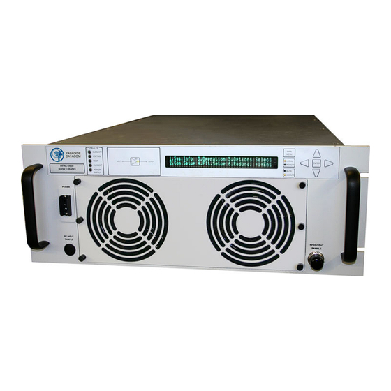
Paradise Datacom 4 RU Chassis Operation Manual (130 pages)
Solid State Power Amplifier
Brand:
Paradise Datacom
| Category:
Amplifier
| Size: 4 MB
Table of Contents
Table of Contents
3
Section 1: General Information
9
Equipment Supplied
10
Inspection
10
Rack Mounting
10
Specifications
10
Safety Considerations
11
High Voltage Hazards
11
High Current Hazards
11
RF Transmission Hazards
12
Electrical Discharge Hazards
12
Shipment
11
1 Introduction
9
Description
9
Figure 1-1: Solid State Power Amplifier Chassis RM Unit
9
Section 2: Operation of Stand-Alone Unit
15
2 Introduction
15
Description of Controls, Indicators and Connectors
15
Front Panel Features
15
Figure 2-1: SSPA Front Panel
15
Front Panel Display
15
Input Sample Port (Optional)
16
Local/Remote Key
16
Main Menu Key
16
Mute/Unmute Key
16
Navigation Keys
16
Output Sample Port
16
Power Toggle
16
Removable Fan Assembly
16
Standby Select Key
16
Rear Panel Features
17
AC Input Port (J10)
17
Figure 2-2: SSPA Rear Panel
17
DC Input Port (J10) (Option)
18
DC Input with N+1 External Power Supply Option
18
Figure 2-3: SSPA Rear Panel, 48VDC Input Power
18
Figure 2-4: Optional N+1 Redundant External Power Supply
19
Figure 2-5: Terminal Block
20
Figure 2-6: Power Supply Alarm Cable Connection
20
RF Input Port (J1)
21
RF Output Port (J2)
21
Switch Port (J3)
21
Table 2-1: Switch Port (J3) Pin Outs
21
Parallel I/O (J7)
22
Program Port (J6)
22
Serial Local (J5)
22
Serial Main (J4)
22
Table 2-2: Serial Main (J4) Pin Outs
22
Table 2-3: Parallel Connector (37 Socket D Connector)
23
Ethernet Port (J9)
24
Hardware Mute (Tx Enable)
24
Link Port (J8)
24
Table 2-4: Ethernet Port (J9) Pin Outs
24
Removable Fan Assembly
25
Figure 2-7: Front Panel Display Menu Structure
25
System Information Sub-Menu
26
Figure 2-8: System Information Menu Structure
26
RU SSPA Chassis Operations Manual 201627 REV X
27
Sys Info
27
Sys Info
28
IP Info
29
Sys Info
29
Firmware Info
30
Firmware Info Page 2 (Version 4.0)
30
Firmware Info Pages 3, 4, 5 and 6 (Version 4.0)
30
IP Info
30
Figure 2-9: Slave Unit Display
31
N+1 Master Info
31
N+1 Slave Info Page
31
N+1 Master Info
32
Communication Setup Sub-Menu
33
Baud Rate
33
Figure 2-10: Communication Setup Sub-Menu
33
Protocol
33
System Address
33
Interface
34
IP Setup
34
More
34
Operation Setup Sub-Menu
35
Attenuation
35
Buzzer
35
Figure 2-11: Operation Setup Sub-Menu
35
Info
35
Mute
35
RF Units
35
Sys. Mode
35
Fault Monitoring Setup Sub-Menu
36
Auxiliary Faults
36
BUC Fault
36
Figure 2-12: Fault Monitoring Setup Sub-Menu
36
RF Switch Faults
36
Fault Latch
37
Low Rf/Automatic Level Control
37
Options Sub-Menu
38
Backup User Settings
38
Figure 2-13: Options Sub-Menu
38
Lamp Test
38
Password
38
Restore
38
Fan Speed
39
Reset
39
Redundancy Sub-Menu
39
Figure 2-14: Redundancy Sub-Menu
39
Standby Mode
39
Standby Select
39
Switching
39
Auto Gain Control
40
N+1 Address
40
N+1 Array Size
40
N+1 System Operation Parameters
40
Priority Select
40
Unit Status
40
N+1 Info
41
Menus
25
Figure 2-15: N+1 Info Menu
41
N+1 Operational Basics (Single Unit)
41
N+1 Operational Basics (Two or more Units)
42
Selecting the Master Unit
42
Figure 2-16: Front Panel Display, Master Unit (Online Indicator Illuminated)
42
Figure 2-17: Front Panel Display, Slave Unit (Online Indicator Dark)
42
Controlling System Operation
43
N+1 Addressing
43
Adjust System Gain
44
N+1 Automatic Gain Control Option
44
N+1 RF Power Measurements
44
N+1 Fault Detection
45
Reflected Power Option
45
Reflected Power Alarm
45
Section 3: Troubleshooting and Maintenance
47
3 Troubleshooting Faults
47
Figure 3-1: Front Panel Fault Display
47
Summary Fault
47
Temperature Fault
47
Voltage Fault
47
Current Fault
48
Fan Fault
48
Low RF Fault
48
Power Supply Fault
48
Modular SSPA Architecture
49
Removable Fans (Intake and Exhaust)
49
Figure 3-2: Remove Fan Tray from SSPA Front Panel
49
Figure 3-3: Unplug and Separate Quick Connectors
49
SSPA Module Removal
50
Figure 3-4: Rear Panel Fan Assembly
50
Figure 3-5: Remove Fan to Access Power Connectors
50
Figure 3-6: SSPA Module Placements
51
Removable Controller Card (Rear Panel)
52
Firmware Upgrade Procedure
52
Figure 3-10: Insert Adapter Tail into Module Programming Connector
52
Figure 3-7: Loosen Thumbscrews from Controller Card Connector Plate
52
Figure 3-8: Remove Controller Card to Gain Access to Connectors
52
Figure 3-9: 4RU RM Sspas Have Two Module Programming Connectors
52
Download Firmware
53
Required Hardware
53
Step-By-Step Procedure
53
Figure 3-11: Command Prompt Console Window Showing Successful Upgrade
54
Changing N+1 Hierarchy
55
Changing Hierarchical Order of Slave Units
55
Exchange N+1 Privileges between Master and Slave Units
55
Add an SSPA Unit to the System
55
Section 4: 1:1 Redundant Operation
57
4 Introduction
57
Figure 4-1: Block Diagram, 1:1 Redundant System
57
Figure 4-2: RM SSPA 1:1 Redundant Systems
58
Hardware
59
Power Supply
59
RF Switch
59
Switch Connector
59
Link Cable
60
Figure 4-3: Outline Drawing, Switch Connector Cable
60
Figure 4-4: Outline Drawing, Link Port Cable
60
Table 4-1: RF Switch Connector Wiring
60
Table 4-2: Link Port (J8) Pin Outs
60
Installation and SSPA Configuration
61
Configuring Amplifiers to Work in 1:1 Redundant Mode
61
Figure 4-5: Cable Connection between SSPA and Waveguide Switch
61
Setting SSPA1 Switching Mode
61
Setting SSPA1 to Work in 1:1 Redundant Mode
61
Setting SSPA1 Unit Status
62
Online / Standby Amplifier Selection
62
Auto Versus Manual Switching Mode
62
Figure 4-6: "Unit 1" Indicator from Front Panel
62
Physically Rotating Transfer Switch
63
Switchover Muting
63
Parallel Port Special Functions
64
Table 4-3: Parallel Connector, Highlighting 1:1 Functions
64
Section 5: 1:2 Internal Redundancy
65
5 Introduction
65
Figure 5-1: Block Diagram, 1:2 Redundant System
65
Required Hardware
66
Figure 5-2: Outline Drawing, Switch Connector Cable
67
Power Supply
67
RF Switches
67
Switch Connector
67
Table 5-1: RF Switch Connector Wiring
67
Figure 5-3: Outline Drawing, Link Port Cable
68
Link Cable
68
Table 5-2: Link Cable Wiring
68
Figure 5-4: 1:2 System Wiring Diagram
69
Installation and SSPA Configuration
70
Installation
70
Setting SSPA Polarization Priority
71
Figure 5-6: "Unit 1" Indicator from Front Panel
71
Online/Standby Amplifier Selection
71
Auto Vs. Manual Switching Mode
72
Parallel Port Special Functions
72
Physically Rotating Transfer Switch
72
Section 6: L-Band Operation
73
6 Block up Converter Overview
73
Figure 6-1: Configurator, Compact Outdoor SSPA, BUC Options
73
Figure 6-2: Schematic, Optional Block up Converter
74
Figure 6-3: Block Diagram of Block up Converter / SSPA System
74
Table 6-1: ZBUC Frequency Specifications
75
Table 6-2: ZBUC RF Output Phase Noise Specification
75
ZBUC Converter Features
75
Zbuc Converter Theory of Operation
75
ZBUC Theory of Operation
75
Smart Reference Technology
76
Figure 6-4: SSPB Chassis with Evolution Series L-Band Modem
77
IFL Cable Considerations
77
Table 6-3: Common Coaxial Cable Characteristics
77
Typical System Configurations
77
Section 7: Remote Control Interface
79
7 Overview
79
Figure 7-1: SSPA Remote Control Interface Stack
79
Remote Control - Parallel
80
Control Outputs
80
Figure 7-2: Parallel I/O Form C Relay
80
RU SSPA Chassis Operations Manual 201627 REV X
81
Control Inputs
81
Figure 7-3: Opto-Isolated Parallel I/O Input
81
Serial Communication Protocol
82
Header Sub-Packet
82
Destination Address
82
Figure 7-4: Basic Communication Packet
82
Figure 7-5: Header Sub-Packet
82
Frame Sync Word
82
Source Address
82
Data Packet
83
Command
83
Figure 7-6: Data Sub-Packet
83
Protocol ID
83
Request ID
83
Table 7-1: Command Byte Values
83
Data Tag
84
Error Status / Data Address
84
Table 7-2: Data Tag Byte Values
84
Data Field
85
Data Length
85
Table 7-3: Error Status Byte Values
85
Trailer Packet
86
Frame Check
86
Timing Issues
86
Figure 7-7: Trailer Sub-Packet
86
Access SSPA Subsystem through Packet Wrapper Technique
87
Figure 7-8: Packet Wrapper Technique
87
Table 7-4: Request Frame Structure
88
Table 7-5: Response Frame Structure
88
Table 7-6: System Setting Details
89
Table 7-7: System Threshold Addressing Details (Read Only)
91
Table 7-8: System Conditions Addressing Details
92
Table 7-9: ADC Data Addressing Details
93
Example 1 Check SSPA Settings
94
Terminal Mode Serial Protocol for Paradise Datacom SSPA
96
Figure 7-9: Terminal Mode Session Example
97
Ethernet Interface
98
Ipnet Interface
98
General Concept
98
Figure 7-10: UDP Redirect Frame Example
99
Table 7-10: OSI Model for RM SSPA Ethernet IP Interface
99
Setting Ipnet Interface
100
Figure 7-11: Initializing Web Interface
101
Using the Rack Mount Web Interface
101
SNMP Interface
103
Introduction
103
SNMP MIB Tree
104
Description of MIB Entities
105
Table 7-11: Detailed Settings
107
Table 7-12: Detailed Thresholds
109
Table 7-13: Detailed Conditions
110
Configuring RM SSPA Unit to Work with SNMP Protocol
111
Connecting to a MIB Browser
112
Figure 7-12: Getif Application Parameters Tab
112
Figure 7-13: Getif Mbrowser Window, with Update Data in Output Data Box
112
Figure 7-14: Getif Mbrowser Window, Setting Settingvalue.5 to '1
113
Appendix A: Ethernet Options Quick Set-Up
115
Figure A-1: TCP/IP Properties Window
115
Appendix B: Proper 10/100 Base-T Ethernet Cable Wiring
119
Figure B-1: Modular Plug Crimping Tool
119
Figure B-2: Transmission Line
119
Figure B-3: Ethernet Cable Pin-Outs
120
Figure B-4: Ethernet Wire Color Code Standards
121
Figure B-5: Wiring Using 568A Color Codes
121
Figure B-6: Wiring Using 568A and 568B Color Codes
121
Appendix C: RM SSPA Control with Paradise Datacom Universal M&C
123
Figure C-1: New Rack Mount SSPA Dialog Window
123
Figure C-2: SSPA Status Window
124
Figure C-3: SSPA Faults Window
124
Figure C-4: SSPA Settings Window
125
Figure C-5: IP Setup Window
125
Appendix D: Automatic Level Control
127
Appendix E: Documentation
129
Advertisement
Advertisement
Related Products
Paradise Datacom 205486 REV F
Paradise Datacom HPAC-100-RM
Paradise Datacom HPAC-125-RM
Paradise Datacom HPAC-150-RM
Paradise Datacom HPAC-200-RM
Paradise Datacom HPAC-250-RM
Paradise Datacom HPAC2030AC Series
Paradise Datacom HPAC2040AC Series
Paradise Datacom HPAC2050AC Series
Paradise Datacom HPAC2075AC Series
Paradise Datacom Categories
Outdoor Light
Landscape Lighting
Light Fixture
Modem
Transformer
More Paradise Datacom Manuals
Login
Sign In
OR
Sign in with Facebook
Sign in with Google
Upload manual
Upload from disk
Upload from URL