PS Engineering PMA6000 Installation And Operation Manual
Audio selector panel with intercom system and marker beacon receiver
Hide thumbs
Also See for PMA6000:
- Pilot's manual and operation manual (7 pages) ,
- Pilot's manual and operation manual (12 pages)
Table of Contents
Advertisement
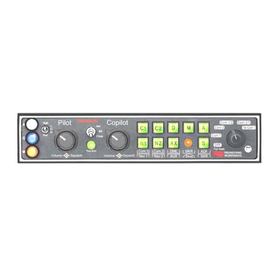
Audio Selector Panel with Intercom System
Any reproduction or retransmittal of this publication, or any portion thereof, without the expressed written
permission of PS Engineering, Inc. is strictly prohibited. For further information contact the Publications
Manager at PS Engineering, Inc., 9800 Martel Road, Lenoir City, TN 37772. Phone (865) 988-9800
9800 Martel Road
Lenoir City, TN 37772
www.ps-engineering.com
PMA6000
PMA6000C
Marker Beacon Receiver
Installation and Operation Manual
Flying never sounded so good™
FAA-Approved TSO C35d
TSO C50c
Document P/N 200-066-0100
Revision 1, March 2005
PS Engineering, Inc. 2005 ©
Copyright Notice
PMA6000M
PMA6000M-C
and
Advertisement
Table of Contents

Related Manuals for PS Engineering PMA6000

Summary of Contents for PS Engineering PMA6000
- Page 1 Any reproduction or retransmittal of this publication, or any portion thereof, without the expressed written permission of PS Engineering, Inc. is strictly prohibited. For further information contact the Publications Manager at PS Engineering, Inc., 9800 Martel Road, Lenoir City, TN 37772. Phone (865) 988-9800...
-
Page 2: Table Of Contents
PS Engineering PMA6000 Series Audio Selector Panel and Intercom System Installation Manual Table of Contents Section I GENERAL INFORMATION....................1-1 INTRODUCTION........................1-1 SCOPE ............................. 1-1 EQUIPMENT DESCRIPTION....................1-1 APPROVAL BASIS - FAA ..................... 1-2 SPECIFICATIONS ........................1-2 EQUIPMENT SUPPLIED ....................... 1-3 EQUIPMENT REQUIRED BUT NOT SUPPLIED.............. - Page 3 Appendix A External PTT Hook Up.....................A Appendix B- Installation Drawing ......................B Appendix D Top Connector wiring (Mono), PMA6000, PMA6000C, PMA6000M, PMA6000M-C D Appendix F -Instructions for Continuing Airworthiness and FAA Form 337 ........E Appendix G RTCA DO160B Environmental Qualification Form............. F Table of Figures Figure 1-1 PMA6000M..........................
-
Page 4: Section I General Information
Option 2 No silver trim around the bezel Opt. 2 Where the functions are identical to all units, it will be referred to herein as a PMA6000. Otherwise, the applicable units will be specified. EQUIPMENT DESCRIPTION The PMA6000-series is a state of the art audio isolation amplifier and audio selector that contains a voice activated (VOX) intercom system. -
Page 5: Approval Basis - Faa
Figure 1-2 PMA6000M-C APPROVAL BASIS - FAA TSO Approval. The PMA6000, PMA6000C and Audio Selector Panels are FAA approved under TSO C50c (Audio Am- plifiers). The PMA6000M and PMA6000M-C are FAA approved under TSO C50c and TSO C35d (Marker Beacon Receivers). -
Page 6: Equipment Supplied
PS Engineering PMA6000 Series Audio Selector Panel and Intercom System Installation Manual Unswitched Inputs: (TEL Ringer, Altimeter DH) Transmitter Selections: (Com 1, Com 2, Com1/2, Com2/1, TEL/Com1) on PMA6000, , PMA6000M (Com 1, Com 2, Com1/2, Com2/1, Com 3) on PMA6000C, PMA6000M-C 4 Ω... -
Page 7: Equipment Required But Not Supplied
PS Engineering PMA6000 Series Audio Selector Panel and Intercom System Installation Manual EQUIPMENT REQUIRED BUT NOT SUPPLIED Speaker, 4 Ω Headphones, mono, up to 6 as required Microphones, up to 6 as required Marker Antenna (75 MHz, VSWR <1:1.5, and appropriate for the airspeed) -
Page 8: Section Ii -Installation
If the PMA6000/M-S is installed in a 27.5 VDC aircraft system, a 15 Ω, 15 Watt dropping resistor (p/n 701-015-1501) should be installed. Failure to do so will generate unnecessary heat inside the unit and may void PS Engineering's warranty. -
Page 9: Mounting Requirements
There must be at least 13.0 VDC present at the bottom connector, pin 20, of the PMA6000 for the power supply to work in its designed regulation. Otherwise, it cannot adequately attenuate power line noise. Shielding can reduce or prevent radiated noise (i.e., beacon, electric gyros, switching power supplies, etc.) However, installation combinations can occur where inter-... -
Page 10: Entertainment Input
Only the person who presses their PTT switch will be heard over the ra- dio. If the pilot and copilot both use the PTT, the copilot position has access to the radio. The pilot posi- tion will have PTT control regardless of the copilot when the PMA6000 is in the F mode. -
Page 11: Transmit Interlock
If the installation replaces a KMA-24 (series -01, -02 or -03), the existing 44 pin connector can be used for the bottom connector of the PMA6000 tray as it is, if it is properly installed and wired. A dropping resistor must be in series with the power in a 28V KMA 24 installation. -
Page 12: Speaker Loads
2.4.14 Digital recorder (-IRS units only) If the PMA6000-series unit is identified with Option 1, there is an internal recorder built into the unit. This stores the last 60 seconds of radio traffic from the selected Com transceiver (the one selected for transmit). -
Page 13: Adjustments
Split Mode. Unit Installation To install the PMA6000, remove the copilot volume and squelch knob. Gently slide the unit into the mounting rack until the hold-down screw is engaged. While applying gentle pressure to the face of the unit, tighten the 3/32" hex-head screw next to the copilot control shaft until the unit is secure. DO NOT OVER TIGHTEN. -
Page 14: Post Installation Checkout
Post Installation Checkout 2.9.1 Required Test Equipment In order to return an aircraft to service after installation of the PMA6000-series with marker beacon re- ceiver, the installer must have access to a Marker Beacon signal generator: IFR NAV401L, NAV402AP, IFR4000 TIC T-30D, T-36C Equivalent test equipment is acceptable as long as the testing requirements can be met. -
Page 15: Marker Checkout, 6000M, 6000M-C Only
PS Engineering PMA6000 Series Audio Selector Panel and Intercom System Installation Manual 2.9.4 Operational Checkout, 3 Com version (6000C and 6000M-C) 1. Complete steps 1 to 10, above. 2. Rotate the mic selector switch to the C 3 position. Verify that the pilot communicates on the trans- ceiver in the Com3 position and the copilot on Com 1. -
Page 16: Section Iii Operation
This section is divided into four sections covering the basic operating areas of the PMA6000 systems. They are: Audio Selector, Transceiver Selection, Intercom, and Marker Beacon Receiver (6000M, 6000M-C 6000M-S and 6000M-S-C only). -
Page 17: Mic Selector Switch, Com 3 (6000C, 6000Mc)
2 while Com 2 has NOT been selected, Com 1 audio will be switched off. In essence, switching the mic selector will not effect the selection of Com audio. Important: When the mic selector is in the full counter clockwise position, the PMA6000 power is re- moved, and it is in the mode. -
Page 18: Intercom
Adjusting the VOX-Squelch control, (6000, 6000M, 6000MC) The PMA6000 provides adjustable VOX squelch controls for the pilot and copilot (the copilot's VOX con- trol also adjusts the passengers VOX squelch). Since the number of microphones open at any one time is reduced, the amount of background noise is diminished. -
Page 19: Push To Talk Intercom Mode
The pilot and copi- lot are individually. All passenger mics are controlled with pin 20. The same pins are used for both mono and stereo PMA6000 Systems. This applies ONLY to units with applicable serial numbers. -
Page 20: Marker Beacon (Pma6000M, Pma6000M-C)
PS Engineering PMA6000 Series Audio Selector Panel and Intercom System Installation Manual The recorder function is automatic. Pressing the momentary switch will cause the last message to play (in- coming radio and transmit sidetone). This will be heard in the pilot headset only. To hear older messages, push the playback button repeatedly to “back up”... - Page 21 PS Engineering PMA6000 Series Audio Selector Panel and Intercom System Installation Manual the need for the avionics shop to reduce the sensitivity in the field so as to prevent early detection of the marker beacons. If your particular installation requires more or less sensitivity, please call the factory for details on how to adjust the receiver sensitivity in the field.
-
Page 22: Section Iv- Warranty And Service
PS Engineering, Inc. warrants this product to be free from defect in material and workmanship for a period of one (1) year from the date of sale by the PS Engineering dealer . -
Page 23: Appendix A External Ptt Hook Up
PTT switch is depressed. A simple modification can be performed to allow proper intercom operation. NOTE: This mod does not alter normal operation. Below are some examples of typical modifications. Contact PS Engineering or the PTT manufacturer for more details if necessary. -
Page 24: Appendix B- Installation Drawing
PS Engineering PMA6000 Series Audio Selector Panel and Intercom System Installation Manual Appendix B- Installation Drawing Cutout size for front mount installation 1.315 in (33.4 mm) 6.31in (160.3 mm) 6.65 in in (167 mm) Side View 0.60 in in (15.25 mm) 1.31 in in... - Page 25 10. Key pin between pin 7 and 8. Com 3 SPR Load Com 3 Spr Load 11. For PMA6000 without marker, marker audio can be interfaced through pin 11 (aux), and will appear when M button pushed. Nav 1 Audio Hi VHF Nav 1 12.
- Page 26 PS Engineering PMA6000 Series Audio Selector Panel and Intercom System Installation Manual Appendix D Top Connector wiring (Mono), PMA6000, PMA6000C, PMA6000M, PMA6000M-C Top Connector PMA6000 (monaural) Notes: 1. All shields should be grounded at audio panel only. other end remains floating.
-
Page 27: Appendix F -Instructions For Continuing Airworthiness And Faa Form 337
. Installed per AC43.13-2, Chapter 2, paragraph 23 (Instrument Panel Mounting). Installed per PS Engineering Installation Operators Manual p/n 200-066-(xxxx), revision X, dated (xx-xx). This unit is FAA-Approved under TSO C50c for audio amplifiers, and TSO C35d for Maker Bea- con Receivers, and meets environmental tests outlined in RTCA DO-170B as appropriate or this aircraft. - Page 28 PS Engineering PMA6000 Series Audio Selector Panel and Intercom System Installation Manual Appendix G RTCA DO160B Environmental Qualification Form Audio Selector Panel/Intercom/Marker Beacon Receiver Part Number: 6000, 6000M, 6000MC FAA TSO Number: C50c, C35b Class A Manufacturer: PS Engineering Incorporated 9800 Martel Road...
Need help?
Do you have a question about the PMA6000 and is the answer not in the manual?
Questions and answers