
Subscribe to Our Youtube Channel
Related Manuals for Tektronix TDS 200-Series


Summary of Contents for Tektronix TDS 200-Series
- Page 1 User Manual TDS 200-Series Digital Real-Time Oscilloscope 071-0398-03 This document supports firmware version FV:v1.00 and above. www.tektronix.com...
- Page 2 Copyright © Tektronix, Inc. All rights reserved. Tektronix products are covered by U.S. and foreign patents, issued and pending. Information in this publication supercedes that in all previously published material. Specifications and price change privileges reserved. Tektronix, Inc., P.O. Box 500, Beaverton, OR 97077...
- Page 3 WARRANTY SUMMARY (TDS 200-Series Digitizing Oscilloscope) Tektronix warrants that the products that it manufactures and sells will be free from defects in materials and workmanship for a period of three (3) years from the date of shipment from an authorized Tektronix distributor. If a product or CRT proves defective within the respective period, Tektronix will provide repair or replacement as described in the complete warranty statement.
- Page 4 WARRANTY SUMMARY (P2100 Probe) Tektronix warrants that the products that it manufactures and sells will be free from defects in materials and workmanship for a period of one (1) year from the date of shipment. If a product proves defective within the respective period, Tektronix will provide repair or replacement as described in the complete warranty statement.
-
Page 5: Table Of Contents
....... . . Defaults (Factory Setup) ......TDS 200-Series Digital Oscilloscope User Manual... - Page 6 ......Viewing Impedance Changes in a Network ....TDS 200-Series Digital Oscilloscope User Manual...
- Page 7 ..........TDS 200-Series Digital Oscilloscope User Manual...
- Page 8 Table of Contents TDS 200-Series Digital Oscilloscope User Manual...
-
Page 9: General Safety Summary
If you suspect there is damage to this product, have it inspected by qualified service personnel. Provide Proper Ventilation. Refer to the manual’s installation instructions for details on installing the product so it has proper ventilation. TDS 200-Series Digital Oscilloscope User Manual... - Page 10 CAUTION indicates a hazard to property including the product. Symbols on the Product. These symbols may appear on the product: Protective Ground Measurment CAUTION Measurment (Earth) Terminal Ground Terminal Refer to Manual Input Terminal TDS 200-Series Digital Oscilloscope User Manual...
-
Page 11: Contacting Tektronix
1-800-833–9200 6:00 a.m. – 5:00 p.m. Pacific time Or contact us by e-mail: support@tektronix.com For product support outside of North America, contact your local Tektronix distributor or sales office. Service Tektronix offers extended warranty and calibration support programs as options on many products. Contact your local Tektronix distributor or sales office. -
Page 12: Product End-Of-Life Handling
When you are ready to reclaim the instrument, you must properly transfer it according to local regulations concerning mercury-containing equipment or ship the instrument to the Tektronix Recycling Operations (RAMS). You can contact Tektronix for the RAMS shipping address and instructions. TDS 200-Series Digital Oscilloscope User Manual viii... -
Page 13: Getting Started
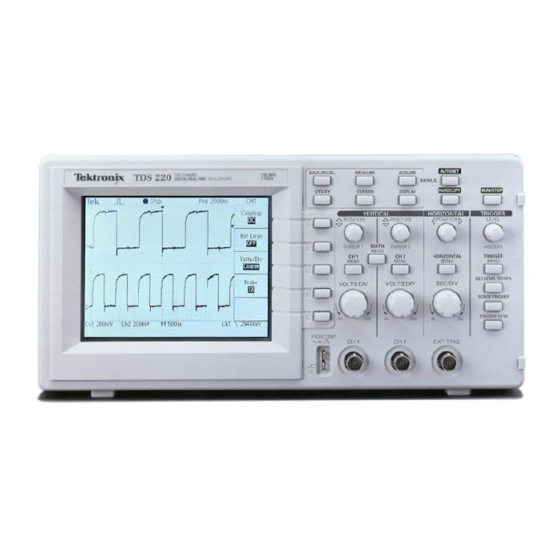
Getting Started TDS 200-Series Digital Oscilloscopes are small, lightweight, benchtop packages that you can use to take ground-referenced measurements. The TDS 210 and TDS 220 oscilloscopes have two-channels; the TDS 224 has four channels. In addition to the list of general features, this section covers the... -
Page 14: General Features
H Digital real-time oscilloscope H Dual time base H Video trigger capability H RS-232, GPIB, and Centronics communication ports easily added with optional extension modules H Variable persistence display H User interface available in ten user-selectable languages TDS 200-Series Digital Oscilloscope User Manual... -
Page 15: Installation
Use the power cord notch to help route the cord to the rear of the instrument and avoid inadvertently disconnecting the power source. Power cord notch Securing cable Security Loop Use the built-in cable channels to secure both your instrument and extension module to your location. TDS 200-Series Digital Oscilloscope User Manual... -
Page 16: Extension Modules
Refer to page 103 for information about the available modules. CAUTION. Electrostatic discharge (ESD) can damage components in the extension module and the oscilloscope. Do not operate your instrument with the extension module connector exposed. Modules slide in and out TDS 200-Series Digital Oscilloscope User Manual... -
Page 17: Functional Check
Push the CH 1 MENU button twice to turn off channel 1, push the CH 2 MENU button to turn on channel 2, repeat steps 2 and 3. For TDS 224, repeat for CH 3 and CH 4. TDS 200-Series Digital Oscilloscope User Manual... -
Page 18: Probe Compensation
CH 1 PROBE COMP Ground connector, turn on the channel, and then press AUTOSET. 2. Check the shape of the displayed waveform. Overcompensated Undercompensated Compensated correctly 3. If necessary, adjust your probe. Repeat as necessary. TDS 200-Series Digital Oscilloscope User Manual... -
Page 19: Self Calibration
To avoid electric shock while using the probe, do not touch metallic portions of the probe head while it is connected to a voltage source. Connect the probe to the instrument and connect the ground terminal to ground before you take any measurements. TDS 200-Series Digital Oscilloscope User Manual... -
Page 20: Probe Attenuation Setting
NOTE. When the Attenuation switch is set to 1X, the P2100 probe limits the bandwidth of the oscilloscope to 7 MHz. To use the full bandwidth of the oscilloscope, be sure to set the switch to 10X. TDS 200-Series Digital Oscilloscope User Manual... -
Page 21: Basic Concepts
The figure below shows a block diagram of the various functions of an oscilloscope and their relationship to each other. Vertical: Acquire data: Waveform Each gain and record: mode and Display channel position 2500 points time base Computer interface (TDS2CM) Trigger AC Line TDS 200-Series Digital Oscilloscope User Manual... -
Page 22: Triggering
AC Line, and External. Input. The most commonly used trigger source is any one of the input channels. The channel you select as a trigger source will function whether it is displayed or not. TDS 200-Series Digital Oscilloscope User Manual... -
Page 23: Types
Refer to Triggering on a Video Signal on page 53. Modes The trigger mode determines how the oscilloscope behaves in the absence of a trigger event. The oscilloscope provides three trigger modes: Auto, Normal, and Single. TDS 200-Series Digital Oscilloscope User Manual... - Page 24 NOTE. When you use the Single trigger mode with the Average acquisition mode, the number of waveforms specified in the number of averages are acquired before the acquisition stops. TDS 200-Series Digital Oscilloscope User Manual...
-
Page 25: Holdoff
To access the Holdoff control, press the HORIZONTAL Menu button, select Holdoff, and use the HOLDOFF knob to change the amount of time in the holdoff period. TDS 200-Series Digital Oscilloscope User Manual... -
Page 26: Coupling
To access the trigger slope control, press the TRIGGER Menu button, select Edge, and use the Slope button to select Rising or Falling. TDS 200-Series Digital Oscilloscope User Manual... -
Page 27: Acquiring Data
There are three acquisition modes: Sample, Peak Detect, and Average. Sample. In this acquisition mode, the oscilloscope samples the signal in evenly spaced intervals to construct the waveform. This mode accurately represents analog signals most of the time. TDS 200-Series Digital Oscilloscope User Manual... -
Page 28: Time Base
You can change the display of waveforms by adjusting their scale and position. When you change the scale, the waveform display will increase or decrease in size. When you change the position, the waveform will move up, down, right, or left. TDS 200-Series Digital Oscilloscope User Manual... -
Page 29: Vertical Scale And Position
You change the horizontal scale of all the waveforms by using the SEC/DIV knob. For example, you might want to see just one cycle of a waveform to measure the overshoot on its rising edge. TDS 200-Series Digital Oscilloscope User Manual... - Page 30 For example, a signal with frequency components of 5 MHz would need to be sampled at 10 Megasamples per second or faster. TDS 200-Series Digital Oscilloscope User Manual...
- Page 31 AUTOSET button, or change the acquisition mode. NOTE. If aliasing occurs, change to the Peak Detect acquisition mode (described on page 16). This mode samples the highest and lowest values so that the oscilloscope can detect faster signals. TDS 200-Series Digital Oscilloscope User Manual...
-
Page 32: Taking Measurements
100 mV/division, then you could easily calculate your peak-to-peak voltage as follows: 5 divisions x 100 mV/division = 500 mV. Cursor Cursor TDS 200-Series Digital Oscilloscope User Manual... -
Page 33: Cursors
You should become familiar with three functions that you will use often when operating your oscilloscope: Autoset, saving a setup, and recalling a setup. Included is a description of the default settings for normal operation of the oscilloscope. TDS 200-Series Digital Oscilloscope User Manual... -
Page 34: Using Autoset
The oscilloscope is set up for normal operation when it is shipped from the factory. You can recall the factory default setup any time you want to operate the oscilloscope using or starting from the factory default settings. TDS 200-Series Digital Oscilloscope User Manual... -
Page 35: Operating Basics
The next figure shows the front panels for a TDS 210 or TDS 220, and for a TDS 224 oscilloscope. TDS 200-Series Digital Oscilloscope User Manual... -
Page 36: Display Area
In addition to displaying waveforms, the display is filled with many details about the waveform and the instrument control settings. Trig'd Pos:-11.30ms Ch1 500mV Ch2 200mV M 500ms W 100ms 750mV 1. Icon display shows acquisition mode. Sample mode Peak detect mode Average mode TDS 200-Series Digital Oscilloscope User Manual... - Page 37 7. Icon shows selected trigger type as follows: – Edge trigger for the rising edge. – Edge trigger for the falling edge. – Video trigger for line sync. – Video trigger for field sync. TDS 200-Series Digital Oscilloscope User Manual...
-
Page 38: Using The Menu System
No marker indicates the channel is not displayed. Using the Menu System The user interface of the TDS 200-series oscilloscopes was designed for easy access to specialized functions through the menu structure. When you press a menu button on the front panel, the associated menu title displays at the top right of the screen. -
Page 39: Action Button Menu Boxes
Waveforms menu, you can use the remaining menu boxes to save or recall waveforms. The SAVE/RECALL, MEASURE, and TRIGGER front panel buttons display Page Selection menu boxes. Page Selection Circular List Action Button Radio Button TDS 200-Series Digital Oscilloscope User Manual... -
Page 40: Waveform Displays
1. A solid black waveform indicates a live waveform display. The waveform remains black when the acquisition is stopped if no controls are changed that make the display accuracy uncertain. Changing the vertical and horizontal controls is allowed on stopped acquisitions. TDS 200-Series Digital Oscilloscope User Manual... -
Page 41: Vertical Controls
For example, changing the trigger controls on a stopped acquisition causes a broken-line waveform. Vertical Controls TDS 210 and TDS 220 TDS 200-Series Digital Oscilloscope User Manual... - Page 42 VOLTS/DIV (CH1, CH 2, CH 3 & CH 4). Selects calibrated scale factors. MATH MENU. Displays waveform math operations menu and can also be used to toggle the math waveform on and off. TDS 200-Series Digital Oscilloscope User Manual...
-
Page 43: Horizontal Controls
NOTE. To make a large adjustment to the horizontal position, change the SEC/DIV to 50 ms, change the horizontal position, and then change the SEC/DIV back to the previous value. HORIZONTAL MENU. Displays the horizontal menu. TDS 200-Series Digital Oscilloscope User Manual... -
Page 44: Trigger Controls
As a holdoff control, it sets the amount of time before another trigger event can be accepted. Refer to Holdoff on page 13 for more information. TDS 200-Series Digital Oscilloscope User Manual... -
Page 45: Menu And Control Buttons
TRIGGER VIEW button is held down. You can use this to see how the trigger settings affect the trigger signal, such as trigger coupling. Menu and Control Buttons TDS 210 and TDS 220 TDS 224 TDS 200-Series Digital Oscilloscope User Manual... - Page 46 HARDCOPY. Starts print operations. An extension module with a Centronics, RS-232, or GPIB port is required. Refer to Optional Accessories on page 103. RUN/STOP. Starts and stops waveform acquisition. TDS 200-Series Digital Oscilloscope User Manual...
-
Page 47: Connectors
Do not connect a voltage source to these ground terminals. CH 1, CH 2, CH 3 & CH 4. Input connectors for waveform display. EXT TRIG. Input connector for an external trigger source. Use the trigger menu to select the trigger source. TDS 200-Series Digital Oscilloscope User Manual... - Page 48 Operating Basics TDS 200-Series Digital Oscilloscope User Manual...
-
Page 49: Application Examples
Using the window function to see waveform details Triggering on odd or even video fields H Analyzing a differential communication signal Using math functions H Viewing impedance changes in a network Using XY mode Using persistence TDS 200-Series Digital Oscilloscope User Manual... -
Page 50: Taking Simple Measurements
When you use more than one channel, the autoset function sets the vertical controls for each channel and uses the lowest-numbered active channel to set the horizontal and trigger controls. TDS 200-Series Digital Oscilloscope User Manual... -
Page 51: Taking Automatic Measurements
6. Push the second CH1 menu box button to select Period. 7. Push the third CH1 menu box button to select Pk-Pk. The frequency, period, and peak-to-peak measurements are shown in the menu and are updated periodically. TDS 200-Series Digital Oscilloscope User Manual... -
Page 52: Measuring Two Signals
You have an audio generator that can inject a test signal at the amplifier input. Connect two oscilloscope channels to the amplifier input and output as shown. Measure both signal levels and use the measurements to calculate the gain. CH 1 CH 2 TDS 200-Series Digital Oscilloscope User Manual... - Page 53 3. Read the peak-to-peak amplitudes for channel 1 and channel 2 in the menu display. 4. Calculate the amplifier gain using the following equations: output amplitude Gain + input amplitude Gain (dB) + 20 log(Gain) TDS 200-Series Digital Oscilloscope User Manual...
-
Page 54: Taking Cursor Measurements
You can see the following measurements in the Cursor menu: H The time at Cursor 1, relative to the trigger. H The time at Cursor 2, relative to the trigger. H The delta time, which is the pulse width measurement. TDS 200-Series Digital Oscilloscope User Manual... -
Page 55: Measuring Rise Time
2. Adjust the VOLTS/DIV knob to set the waveform amplitude to about five divisions. 3. Push the CH 1 MENU button to see the CH1 menu if it is not displayed. 4. Push the Volts/Div button to select Fine. TDS 200-Series Digital Oscilloscope User Manual... - Page 56 This is the 90% point on the waveform. 11. The delta readout in the cursor menu is the rise time of the waveform. 5 divisions NOTE. The TDS2MM extension module provides rise time as an automatic measurement. TDS 200-Series Digital Oscilloscope User Manual...
-
Page 57: Measuring Ring Frequency
4. Use the CURSOR 2 knob to place a cursor on the second peak of the ring. You can see the delta time and frequency (the measured ring frequency) in the Cursor menu. TDS 200-Series Digital Oscilloscope User Manual... -
Page 58: Measuring Ring Amplitude
4. Use the CURSOR 2 knob to place a cursor on the lowest point of the ring. You can see the following measurements in the cursor menu: H The delta voltage (peak-to-peak voltage of the ringing) H The voltage at Cursor 1 H The voltage at Cursor 2 TDS 200-Series Digital Oscilloscope User Manual... -
Page 59: Analyzing Signal Detail
Use the Contrast Increase and Contrast Decrease menu box buttons to adjust the contrast to see the noise more easily. Peak detect emphasizes noise spikes and glitches in your signal, especially when the time base is set to a slow setting. TDS 200-Series Digital Oscilloscope User Manual... -
Page 60: Separating The Signal From Noise
Averaging reduces random noise and makes it easier to see detail in a signal. In the example below, a ring shows on the rising and falling edges of the signal when the noise is removed. TDS 200-Series Digital Oscilloscope User Manual... -
Page 61: Capturing A Single-Shot Signal
8. If the readout at the top of the screen does not display Armed or Ready, then push the RUN/STOP button to start the acquisition. When the relay opens, the oscilloscope is triggered and captures the event. TDS 200-Series Digital Oscilloscope User Manual... -
Page 62: Optimizing The Acquisition
When the next acquisition is captured with the new settings, you can see more detail about the relay contact opening. You can now see that the contact bounces several times as it opens. TDS 200-Series Digital Oscilloscope User Manual... -
Page 63: Measuring Propagation Delay
You suspect that the memory timing in a microprocessor circuit is marginal. Set up the oscilloscope to measure the propagation delay between the chip-select signal and the data output of the memory device. Data CH 1 CH 2 TDS 200-Series Digital Oscilloscope User Manual... - Page 64 7. Use the CURSOR 1 knob to place the cursor on the active edge of the chip-select signal. 8. Use the CURSOR 2 knob to place the second cursor on the data output transition. 9. Read the propagation delay in the Delta readout in the cursor menu. TDS 200-Series Digital Oscilloscope User Manual...
-
Page 65: Triggering On A Video Signal
You are testing the video circuit in a piece of medical equipment and need to display the video output signal. The video output is an NTSC standard signal. Use the video trigger to obtain a stable display. 75 W terminator CH 1 TDS 200-Series Digital Oscilloscope User Manual... -
Page 66: Triggering On Video Fields
2. Push the top menu box button to select Video. 3. Push the Sync menu box button to select Line. 4. Adjust the horizontal SEC/DIV knob to see a complete video line across the screen. TDS 200-Series Digital Oscilloscope User Manual... -
Page 67: Using The Window Function To See Waveform Details
Incoming video signal 75 W terminator CH 1 Using the Window Function to See Waveform Details You can use the window function to examine a specific portion of a waveform without changing the main display. TDS 200-Series Digital Oscilloscope User Manual... - Page 68 7. Adjust the SEC/DIV knob to set the width of the window (area to be expanded). 8. Adjust the HORIZONTAL POSITION knob to position the window around the portion of the waveform you want to expand. TDS 200-Series Digital Oscilloscope User Manual...
-
Page 69: Triggering On Odd Or Even Video Fields
For example, the field rate for NTSC video is 60 Hz. For stable triggering, you should set the holdoff period to at least the field rate (16.7 ms), but not to more than twice the field rate (33 ms). TDS 200-Series Digital Oscilloscope User Manual... - Page 70 11. Push the ACQUIRE button to see the Acquire menu. 12. Set SEC/DIV to 10 ms. 13. Adjust the HORIZONTAL POSITION knob to about 1.5 ms. 14. Push the HORIZONTAL MENU button to see the Main menu. TDS 200-Series Digital Oscilloscope User Manual...
- Page 71 With 21 ms of holdoff time you can With 500 ns of holdoff time, you cannot see any line information because the easily see one clear line alternating fields overlap TDS 200-Series Digital Oscilloscope User Manual...
-
Page 72: Analyzing A Differential Communication Signal
Because this is a differential signal, you use the math function of the oscilloscope to view a better representation of the waveform. CH 1 CH 2 TDS 200-Series Digital Oscilloscope User Manual... -
Page 73: Tds 210 And Tds 220 (Firmware V 2.00 And Above), And Tds 224 (All Versions) Oscilloscopes
NOTE. Vertical sensitivity should match on waveforms used for math operations. If they do not match, and you use cursors to measure the waveform result, an U displays that represents unknown in the level and delta readouts. TDS 200-Series Digital Oscilloscope User Manual... -
Page 74: Tds 210 And Tds 220 Oscilloscopes (Firmware Below V 2.00) Without A Tds2Mm
2. 2. Push the MATH MENU button and then push the CH1+CH2 menu box button to display a new waveform that is the difference between the displayed waveforms. TDS 200-Series Digital Oscilloscope User Manual... -
Page 75: Viewing Impedance Changes In A Network
Connect the oscilloscope to monitor the input and output of the circuit and capture the changes that occur as you vary the tempera- ture. Circuit CH 1 CH 2 TDS 200-Series Digital Oscilloscope User Manual... - Page 76 10. Push the Contrast Increase or Decrease menu box buttons to adjust the contrast of the display for optimal viewing. As you adjust the ambient temperature, the display persistence captures the changes in the characteristics of the circuit. TDS 200-Series Digital Oscilloscope User Manual...
-
Page 77: Reference
Reference This section describes the menus and operating details associated with each front-panel menu button. Reference Topic Page Acquire Autoset Cursor Display Hard copy Horizontal controls Math Measure Save/Recall Trigger controls Utility Vertical controls TDS 200-Series Digital Oscilloscope User Manual... -
Page 78: Acquire
Select Number of Averages Key Points If you probe a noisy square wave signal that contains intermittent, narrow glitches, the waveform displayed will vary depending on the acquisition mode you choose. Sample Peak Detect Average TDS 200-Series Digital Oscilloscope User Manual... - Page 79 2,500 point waveform record. Peak Detect. Use Peak Detect acquisition mode to detect glitches as narrow as 10 ns and to limit the possibility of aliasing. This mode is effective when at 5 ms/div or slower. TDS 200-Series Digital Oscilloscope User Manual...
- Page 80 Peak Detect to Sample. When there is enough waveform noise, a typical peak detect display shows large black areas. The TDS 200-series oscilloscopes displays this area with diagonal lines to improve display performance. Typical peak detect display...
- Page 81 Stopping the Acquisition. While acquisition is running, the waveform display is live. Stopping the acquisition freezes the display. In either mode, the waveform display can be scaled or positioned with the vertical and horizontal controls. TDS 200-Series Digital Oscilloscope User Manual...
-
Page 82: Autoset
Trigger type Edge Trigger source Lowest numbered channel displayed Trigger coupling Adjusted to DC, Noise Reject, or HF Reject Trigger slope Rising Trigger holdoff Minimum Trigger level Set to 50% Display format Trigger mode Auto TDS 200-Series Digital Oscilloscope User Manual... -
Page 83: Cursors
* Only available on the TDS 224 oscilloscope. Key Points Cursor Movement. Use the CH 1 and CH 2 Vertical Position knobs to move cursors 1 and 2. You can move the cursors only while the Cursor menu is displayed. TDS 200-Series Digital Oscilloscope User Manual... -
Page 84: Display
XY format displays channel 1 in the horizontal axis and channel 2 in the vertical axis Contrast Darkens the black (or gray) areas of the Increase display Contrast Lightens the white areas of the display Decrease TDS 200-Series Digital Oscilloscope User Manual... - Page 85 The following functions do not work in XY display format: H Ref or Math waveforms H Cursors H Autoset (resets display format to YT) H Time base controls H Trigger controls TDS 200-Series Digital Oscilloscope User Manual...
-
Page 86: Horizontal
(volts) or holdoff time (sec) The holdoff value is displayed NOTE. You can push the Window menu box button to switch between an entire waveform display and an enlarged, more detailed part of it. TDS 200-Series Digital Oscilloscope User Manual... - Page 87 Holdoff begins when the instrument recognizes a trigger event and disables the trigger system until acquisition is complete. The trigger system remains disabled during the holdoff time that follows each recognized trigger event. TDS 200-Series Digital Oscilloscope User Manual...
-
Page 88: Math
Channels 3 and 4 are added together * Only available on the TDS 224 oscilloscope. NOTE. The optional TDS2MM measurement extension module adds the FFT feature to the oscilloscope. See the TDS 200–Series Extension Modules Instructions Manual. TDS 200-Series Digital Oscilloscope User Manual... -
Page 89: Tds 210 And Tds 220 Oscilloscopes (Firmware Below V 2.00) Without A Tds2Mm
H The TDS2MM Module does not have the CH1–CH2 and CH2–CH1 math functions. To do the same functions, invert the channel you want to subtract (using the CH1 or CH2 menu) and then select the CH1+CH2 math function. TDS 200-Series Digital Oscilloscope User Manual... - Page 90 NOTE. You can push the menu box button of the enabled math operation on a TDS 210 or TDS 220 to switch between the math waveform and the channels used to create the math waveform. TDS 200-Series Digital Oscilloscope User Manual...
-
Page 91: Measure
Type menu boxes NOTE. The optional TDS2MM measurement extension module adds the rise time, fall time, positive pulse width, and negative pulse width measurements to the oscilloscope. See the TDS 200–Series Extension Modules Instructions Manual. TDS 200-Series Digital Oscilloscope User Manual... - Page 92 Period Calculates the time for one cycle Pk-Pk Calculates the absolute difference between the maximum and minimum peaks of the entire waveform Freq Calculates the frequency of the waveform by measuring the first cycle TDS 200-Series Digital Oscilloscope User Manual...
-
Page 93: Save/Recall
When turning the instrument on, all settings return to the settings that were in place when the instrument was turned off. Recalling the Factory (Default) Setup. You can recall the default Factory Setup to initialize the instrument to a known setup. TDS 200-Series Digital Oscilloscope User Manual... - Page 94 For the TDS 224 oscilloscope, you can store four reference waveforms, although you can only display two at a time. You can display reference waveforms simultaneously with current waveform acquisitions. Recalled waveforms are not adjustable. TDS 200-Series Digital Oscilloscope User Manual...
-
Page 95: Trigger Controls
Selects the components of the trigger signal applied to the trigger circuitry Noise Reject HF Reject LF Reject * Only available on the TDS 224 oscilloscope. ** Only available on the TDS 210 and TDS 220 oscilloscopes. TDS 200-Series Digital Oscilloscope User Manual... - Page 96 5; this extends the trigger level range. AC Line Source. The AC Line trigger source uses the power signal as the trigger source. Trigger coupling is set to DC and the trigger level to 0 volts. TDS 200-Series Digital Oscilloscope User Manual...
- Page 97 Trigger View. Pushing TRIGGER VIEW displays the trigger waveform until the button is released. When in Trigger View mode, all front-panel buttons are disabled except HARDCOPY. TDS 200-Series Digital Oscilloscope User Manual...
- Page 98 ** Only available on the TDS 210 and TDS 220 oscilloscopes. Key Points Sync Pulses. When you choose Normal Polarity, the trigger always occurs on negative-going sync pulses. If your video signal has positive-going sync pulses, use the Inverted Polarity selection. TDS 200-Series Digital Oscilloscope User Manual...
-
Page 99: Utility
Displays a list of any errors logged This list is useful when contacting a Tektronix Service Center for help Language English Selects the display language of the French operating system German Italian Spanish Portuguese Japanese Korean Simplified Chinese Traditional Chinese TDS 200-Series Digital Oscilloscope User Manual... - Page 100 Vertical Lists vertical parameters of channels Trigger Lists trigger parameters Misc Lists the model of the instrument and the software version number If an extension module is installed, lists values of the communications parameters TDS 200-Series Digital Oscilloscope User Manual...
-
Page 101: Vertical
Invert Not available on a TDS 210 or TDS 220 (firmware below V 2.00) without a TDS2MM installed * Bandwidth is not valid for the P2100 probe when the switch is set to 1X. TDS 200-Series Digital Oscilloscope User Manual... -
Page 102: Hard Copy
Centronics, RS-232, or GPIB port be installed and connected to a printer. Refer to the manual supplied with your extension module for instructions on connections and using the module. Refer to Optional Accessories on page 103 for information about the available extension modules. TDS 200-Series Digital Oscilloscope User Manual... -
Page 103: Appendix A: Specifications
Appendix A: Specifications All specifications apply to the TDS 200-Series Digital Oscilloscopes and a P2100 probe with the Attenuation switch set to 10X unless noted otherwise. To meet specifications, two conditions must first be met: H The instrument must have been operating continuously for twenty minutes within the specified operating temperature. - Page 104 Also, refer to Overvoltage Category description on page 102. Time delay between 150 ps channels, typical * Bandwidth is not valid for the P2100 probe when the switch is set to 1X. TDS 200-Series Digital Oscilloscope User Manual...
- Page 105 * Bandwidth is not valid for the P2100 probe when the switch is set to 1X. ** The oscilloscope reverts to Sample mode when the sec/div (horizontal scale) is set from 2.5 ms/div to 5 ns/div. The Sample mode can still capture 10 ns glitches. TDS 200-Series Digital Oscilloscope User Manual...
- Page 106 * Bandwidth is not valid for the P2100 probe when the switch is set to 1X. ** The oscilloscope reverts to Sample mode when the sec/div (horizontal scale) is set from 2.5 ms/div to 5 ns/div. The Sample mode can still capture 10 ns glitches. TDS 200-Series Digital Oscilloscope User Manual...
- Page 107 CAT III or 100 V DC CAT III 1X position 150 V CAT I or 150 V DC CAT I 150 V CAT II or 150 V DC CAT II 100 V CAT III or 100 V DC CAT III TDS 200-Series Digital Oscilloscope User Manual...
- Page 108 (–4 div × s/div) to 20 ms Position Range 5 ns/div to 10 ns/div (–4 div × s/div) to 50 ms 25 ns/div to 100 ms/div (–4 div × s/div) to 50 s 250 ms/div to 5 s/div TDS 200-Series Digital Oscilloscope User Manual...
- Page 109 ±8 divisions from center of screen Internal TDS 210 and TDS 220 only ±1.6 V ±8 V EXT/5 * Bandwidth is not valid for the P2100 probe when the switch is set to 1X. TDS 200-Series Digital Oscilloscope User Manual...
- Page 110 500 ns to 10 s Measurements Cursors Voltage difference between cursors (DV) Time difference between cursors (DT) Reciprocal of DT in Hertz (1/DT) Automated Measure- Cycle RMS, Mean, Pk – Pk, Period, Frequency ments TDS 200-Series Digital Oscilloscope User Manual...
- Page 111 Nonoperating –20° C to +60° C Cooling Method Convection ≤ 90% relative humidity Humidity +40° C or below ≤ 60% relative humidity +41° C to +50° C Altitude Operating 3,000 m Nonoperating 15,000 m TDS 200-Series Digital Oscilloscope User Manual...
- Page 112 50 g, 11 ms, half sine Mechanical Size Height 151.4 mm (5.96 in.) Width 304.8 mm (12 in.) Depth 120.7 mm (4.75 in.) Weight (approximate) When packaged for domestic 3.6 kg (8.0 lbs) shipment TDS 200-Series Digital Oscilloscope User Manual...
- Page 113 200 MHz to 1000 MHz under a 3 V/m RF field. Ambient RF fields may induce triggering when trigger threshold is offset less than 2.5 major divisions from ground reference. TDS 200-Series Digital Oscilloscope User Manual...
- Page 114 CAT III Distribution-level mains, fixed installation CAT II Local-level mains, appliances, portable equipment CAT I Signal levels in special equipment or parts of equipment, telecommunications, electronics Adjustment Interval The recommended calibration interval is one year TDS 200-Series Digital Oscilloscope User Manual...
-
Page 115: Appendix B: Accessories
Optional Accessories TDS2MM Measurement Extension Module. The TDS2MM module plugs directly into the rear panel of any TDS 200-Series oscilloscope. This module provides full GPIB and RS-232 compatibility and a Centronics port for hard copy output. The module allows measurement of rise time, fall time, and positive and negative pulse width. - Page 116 RM200 Rackmount Kit. The RM200 Rackmount Kit lets you install a TDS 200-Series oscilloscope into an industry- standard 19 inch rack. The rackmount kit requires seven inches of vertical rack space. You can turn the oscilloscope power on or off from the front of the rackmount kit.
- Page 117 Transit Case. The transit case (HCTDS32) provides shock, vibration, impact and moisture protection for the instrument when you transport it from one place to another. The required soft case fits inside the transit case. TDS 200-Series Digital Oscilloscope User Manual...
- Page 118 Appendix B: Accessories TDS 200-Series Digital Oscilloscope User Manual...
-
Page 119: Appendix C: General Care And Cleaning
2. Use a soft cloth dampened with water to clean the instrument. Use an aqueous solution of 75% isopropyl alcohol for more efficient cleaning. CAUTION. To avoid damage to the surface of the instrument or probes, do not use any abrasive or chemical cleaning agents. TDS 200-Series Digital Oscilloscope User Manual... - Page 120 General Care and Cleaning TDS 200-Series Digital Oscilloscope User Manual...
-
Page 121: Glossary
This reduces the apparent noise. The oscilloscope acquires data as in the sample mode and then averages it according to a specified number of averages. TDS 200-Series Digital Oscilloscope User Manual... - Page 122 Triggering that occurs when the oscilloscope detects the source passing through a specified voltage level in a specified direction (the trigger slope). GPIB A serial communication port used to connect to a hard-copy device, computer, controller, or terminal. TDS 200-Series Digital Oscilloscope User Manual...
- Page 123 A mode in which the oscilloscope creates a pair of record points during each sample interval. Each pair consists of the maximum and minimum input voltage during the interval. Persistence A method of retaining old data on the display for a period of time. TDS 200-Series Digital Oscilloscope User Manual...
- Page 124 A digitizing technique that samples the input signal with a sample frequency of at least four times the oscilloscope bandwidth. (TDS 200-series oscilloscopes sample at 10 times the bandwidth or more.) Combined with (sinx)/x interpolation, all frequency components of the input up to the bandwidth are accurately displayed.
- Page 125 It is useful for studying phase relationships between two waveforms. YT Format The conventional oscilloscope display format. It shows the voltage of a waveform record (on the vertical axis) as it varies over time (on the horizontal axis). TDS 200-Series Digital Oscilloscope User Manual...
- Page 126 Glossary TDS 200-Series Digital Oscilloscope User Manual...
-
Page 127: Index
46 measuring ring frequency, 45 measuring rise time, 43 calibration, 87 measuring two signals, 40 Centronics, 2, 103 optimizing the acquisition, 50 CH 1 peak detect, using, 47 reducing noise, 48 connector, 35 TDS 200-Series Digital Oscilloscope User Manual... - Page 128 CURSOR button, 34, 71 cursors, 21 application example, 42 GPIB, 2, 103 measurements, 42 graticule, 20, 72 time, 21 gray waveforms, 28 voltage, 21 ground marker, 26 probe terminal, 7 terminals, 35 description, general, 1 TDS 200-Series Digital Oscilloscope User Manual...
- Page 129 MATH MENU button, 30 measure, menu, 79 MEASURE button, 34 measurements PAL, 54, 86 automatic, 21, 79 peak detect, 66, 67 basic concepts, 20 persistence, 72, 73 cursor, 21, 42 ports, 2 frequency, 80 TDS 200-Series Digital Oscilloscope User Manual...
- Page 130 25 SAVE/RECALL button, 34, 81 readout, 25 saving menu, 83 setups, 22, 81 modes, 11 waveforms, 82 Auto, 12, 84 scaling waveforms, basic concepts, Normal, 12, 84 Single, 12, 84 scan mode, 69, 75 TDS 200-Series Digital Oscilloscope User Manual...
- Page 131 UTILITY button, 34 window zone, 26, 75 vectors, 72 XY, 72 vertical application example, 64 menu, 89 display, 73 position, 17 scale, 17 status, 88 video trigger, application example, YT, 72 voltage cursors, 21, 71 TDS 200-Series Digital Oscilloscope User Manual...
- Page 132 Index TDS 200-Series Digital Oscilloscope User Manual...
Need help?
Do you have a question about the TDS 200-Series and is the answer not in the manual?
Questions and answers